2016 BMW M4 light
[x] Cancel search: lightPage 178 of 228
ted speed for the tyres fitted must be dis‐
played in the driver's field of view. The sticker
is available from a Service Partner or a qualified
specialist workshop.
If winter tyres are fitted, observe and comply
with the respectively permitted maximum
speed.
Interchanging front and rear wheels
The manufacturer of your vehicle advises
against interchanging the front and rear
wheels. This could impair vehicle handling
Such a change is not permitted in vehicles with
different tyre or rim dimensions on the front
and rear axles.
Tyre storage
Store wheels and tyres in a cool, dry and pref‐
erably dark place when not in use.
Protect tyres against contamination from oil,
grease and fuel.
Do not exceed the maximum tyre pressure in‐
dicated on the tyre's side wall.
Remedying flat tyres Safety measures▷Park the vehicle on a solid surface and as
far away from moving traffic as possible.▷Switch on hazard warning lights.▷Protect the vehicle against rolling, by ap‐
plying the parking brake.▷Engage the steering wheel lock in the
straight ahead position of the wheels.▷Allow all vehicle occupants get out of the
vehicle and guide them out of the danger
area, for example behind the crash barrier.▷Set up warning triangle an appropriate dis‐
tance away.Mobility system
Principle With the mobility system, minor tyre damage
can be quickly sealed, to allow you to drive on.
To do that, liquid sealant is pumped into the
tyres which encloses the damage from the in‐ side when it hardens.
The compressor can be used to check the tyre
inflation pressure.
Notes▷Please observe the notes on the applica‐
tion of the Mobility system which are on
the compressor and the sealant container.▷Applying the Mobility system can be inef‐
fective for tyre damage as from a size of
approximately 4 mm.▷Contact a Service Partner or a qualified
specialist workshop if you are unable to put
the tyre back in operation.▷If possible, foreign matter that has penetra‐
ted the tyre should remain inside the tyre.▷Remove the speed limit sticker from the
sealant container and attach to the steer‐
ing wheel.▷Using sealants can damage the TPM wheel
electronics. If sealant is used, check the
electronics as soon as you get an opportu‐
nity and have them replaced if necessary.
DANGER
A blocked exhaust pipe or inadequate
ventilation can allow harmful exhaust fumes to
penetrate the vehicle. The exhaust gas con‐
tains carbon monoxide, which is colourless and
odourless, but highly toxic. In enclosed spaces,
the exhaust fumes can also build up outside
the vehicle. Danger of fatal injury. Keep the ex‐
haust pipe clear and ensure sufficient ventila‐
tion.◀
Storage
Mobility system is located under boot floor.
Seite 178MobilityWheels and tyres178
Online Edition for Part no. 01 40 2 964 013 - VI/15
Page 186 of 228

Different messages are shown on the display,
depending on the engine oil level. Follow these
messages.
If there is too little engine oil, within the next
200 km, approximately 120 miles top up en‐
gine oil, see page 186.
Detailed measurement
Principle In the detailed measurement, the engine oil
level is checked and shown on a scale.
If the engine oil level reaches the minimum, a
Check Control message is shown.
During the measurement, the idle speed is
slightly raised.
Requirements▷Vehicle is on an even road.▷Manual gearbox: gear lever in neutral posi‐
tion, clutch and accelerator pedal not de‐
pressed.▷M double clutch transmission: selector
lever in selector lever position N and accel‐
erator pedal not depressed.▷Engine is running and is at operating tem‐
perature.
Carrying out a detailed measurement
Carry out a detailed measurement of the en‐
gine oil level:
1."Vehicle information"2."Vehicle status"3. "Measure engine oil level"4."Start measurement"
The engine oil level is checked and shown on a
scale.
Duration: approximately 1 minute.
Adding engine oil
Notes ATTENTION
Too little engine oil causes engine dam‐
age. Danger of damage to property.
Top up the engine oil within the next 200 km,
approximately 120 miles.◀
ATTENTION
Too much engine oil can damage the en‐
gine or the catalytic converter. Danger of dam‐
age to property. Do not top up with too much
engine oil. If you fill too much engine oil, have
the excess extracted by a Service Partner or a
qualified specialist workshop.◀
WARNING
Service products, for example oils,
greases, coolants and fuels, can contain sub‐
stances that are harmful to health. Danger of
injury or life. Comply with the notes on the
containers. Do not allow service products to
come into contact with clothing, skin eyes. Do
not pour service products into other bottles.
Keep service products out of the reach of chil‐
dren.◀
General Do not top up engine oil unless message isdisplayed in instrument cluster. The top-up
amount is specified in the message on the in‐
strument cluster.
Switch off the ignition and securely stop the
vehicle before topping up with engine oil.
Spilled engine oil can damage carbon parts.
Wipe up spilled engine oil with a lint-free cloth.
Overview
The oil filler neck is in the engine compart‐
ment, see page 182.Seite 186MobilityEngine oil186
Online Edition for Part no. 01 40 2 964 013 - VI/15
Page 189 of 228

CoolantVehicle equipmentThis chapter describes all standard, national
and special equipment provided in the model
series. Equipment not available in the vehicle is
therefore also described, for example the se‐
lected special equipment or national version.
This also applies to safety-relevant functions
and systems. Comply with the relevant na‐
tional regulations when using the correspond‐
ing functions and systems.
General
The vehicle has two coolant tanks located in
the engine compartment.
To guarantee operational safety of the vehicle,
always check the coolant levels of both coolant
tanks.
Notes WARNING
If the cooling system is opened when the
engine is hot, coolant can escape and cause
scalds. Danger of injury. Only open the cooling
system when the engine has cooled down.◀
WARNING
Additives are harmful to health and incor‐
rect additives can damage the engine. Danger
of injury and damage to property. Do not allow
additives to come into contact with clothing,
skin or eyes, and do not swallow them. Only
use suitable additives.◀
Coolant is a mixture of water and an additive.
Not all commercially available additives are
suitable for the vehicle. Information regarding
suitable additives is available from a Service
Partner or a qualified specialist workshop.Coolant level
Overview
Depending on the engine version, the coolant
tank is located on the right or left of the engine
compartment.
Checking1.Allow the engine to cool down.2.Turn cap on coolant tank slightly anti-
clockwise until it starts to open, then allow
the pressure to escape.3.Open cap on coolant tank.4.The coolant level is correct if it is between
the Min. and Max. marks in the filler neck.
Topping up
1.Allow the engine to cool down.2.Turn the cap on the coolant tank slightly
anti-clockwise until it starts to open, thenSeite 189CoolantMobility189
Online Edition for Part no. 01 40 2 964 013 - VI/15
Page 192 of 228

The vehicle owner can contact his/her Service
Partner or a qualified specialist workshop to
object to the entry in the electronic service his‐
tory, the associated data storage in the vehicle
and data transfer to the vehicle manufacturer,
in relation to his/her time as the vehicle owner.
In that case, no entry is made in the electronic
service history of the vehicle.
Maintenance entered is shown on the Control
Display, see page 88.
For Australia/New Zealand:
maintenance
No maintenance work other than normal main‐
tenance is required to keep the emission levels
of your vehicle within the design limits.
Socket for on-board
diagnosis, OBD
Note ATTENTION
Incorrect use of the on-board diagnosis
socket can result in malfunctions in the vehi‐
cle. Danger of damage to property. The on-
board diagnosis socket is only allowed to be
used by a Service Partner, a qualified specialist
workshop or other authorised persons.◀Position
The OBD socket for checking components de‐
finitive in terms of the composition of the ex‐
haust emissions is on the driver's side.
Emissions
▷The warning light flashes:
Engine malfunction that could
damage the catalytic converter.
Have the vehicle checked as soon
as possible.▷The warning light is illuminated:
Deterioration of exhaust emissions. Have
the vehicle checked as soon as possible.
Recycling
The manufacturer of your vehicle recommends
handing the vehicle in at a take-back point
nominated by the manufacturer at the end of
its life cycle. The regulations concerning the
returning of end-of-life vehicles may vary from
country to country. Further information is avail‐
able from a Service Partner or a qualified spe‐
cialist workshop.
Seite 192MobilityMaintenance192
Online Edition for Part no. 01 40 2 964 013 - VI/15
Page 193 of 228
Replacing partsVehicle equipmentThis chapter describes all standard, national
and special equipment provided in the model
series. Equipment not available in the vehicle is
therefore also described, for example the se‐
lected special equipment or national version.
This also applies to safety-relevant functions
and systems. Comply with the relevant na‐
tional regulations when using the correspond‐
ing functions and systems.
On-board tool kit
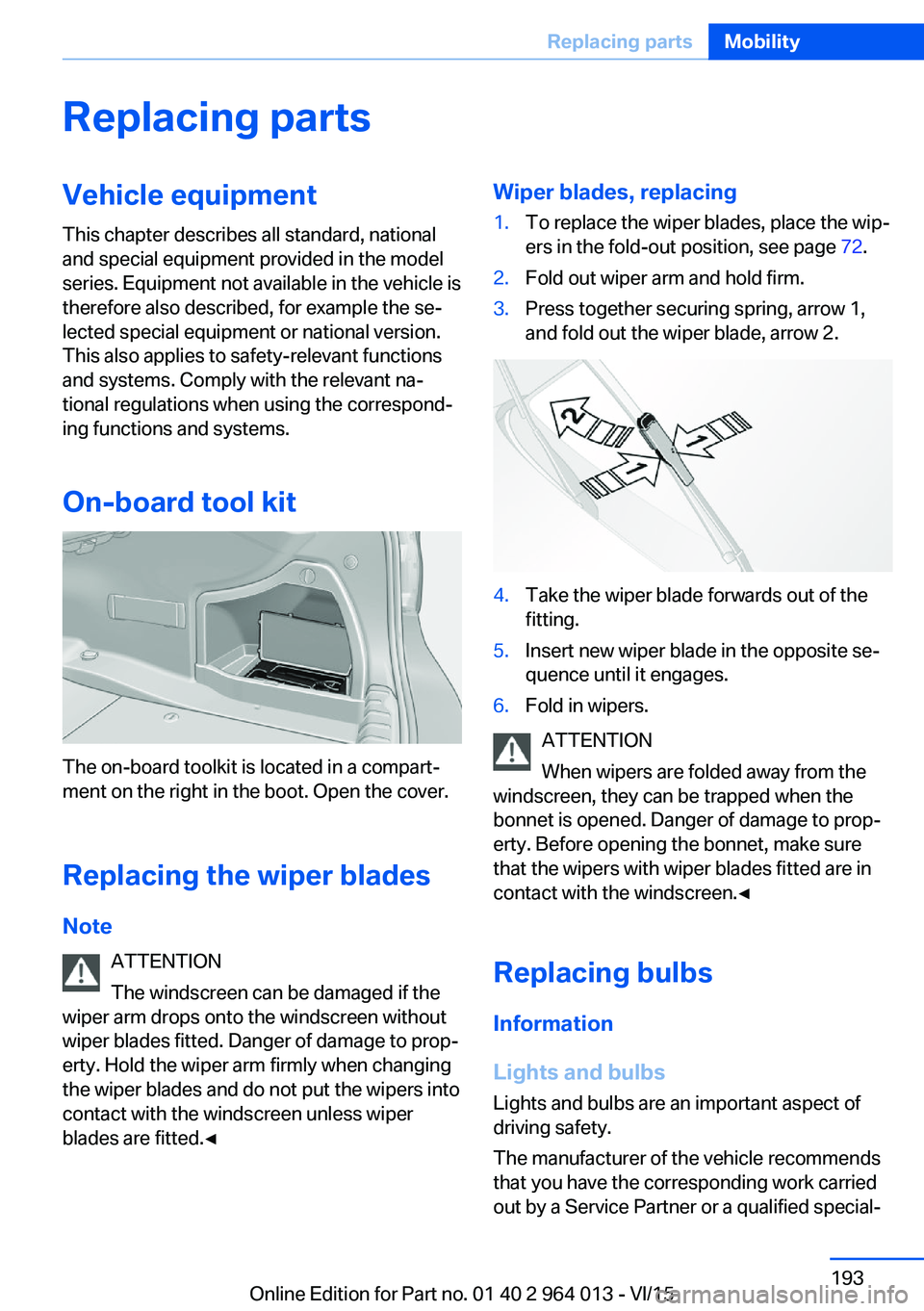
The on-board toolkit is located in a compart‐
ment on the right in the boot. Open the cover.
Replacing the wiper blades Note ATTENTION
The windscreen can be damaged if the
wiper arm drops onto the windscreen without
wiper blades fitted. Danger of damage to prop‐
erty. Hold the wiper arm firmly when changing
the wiper blades and do not put the wipers into
contact with the windscreen unless wiper
blades are fitted.◀
Wiper blades, replacing1.To replace the wiper blades, place the wip‐
ers in the fold-out position, see page 72.2.Fold out wiper arm and hold firm.3.Press together securing spring, arrow 1,
and fold out the wiper blade, arrow 2.4.Take the wiper blade forwards out of the
fitting.5.Insert new wiper blade in the opposite se‐
quence until it engages.6.Fold in wipers.
ATTENTION
When wipers are folded away from the
windscreen, they can be trapped when the
bonnet is opened. Danger of damage to prop‐
erty. Before opening the bonnet, make sure
that the wipers with wiper blades fitted are in
contact with the windscreen.◀
Replacing bulbs
Information
Lights and bulbs
Lights and bulbs are an important aspect of
driving safety.
The manufacturer of the vehicle recommends
that you have the corresponding work carried
out by a Service Partner or a qualified special‐
Seite 193Replacing partsMobility193
Online Edition for Part no. 01 40 2 964 013 - VI/15
Page 194 of 228
ist workshop, if you are not familiar with it or it
is not described here.
A box containing spare bulbs is available from
a Service Partner or a qualified specialist work‐
shop.
WARNING
Lamps can become hot during operation.
Contact with the lamps can lead to burns. Dan‐
ger of injury. Only replace lamps in cooled-
down condition.◀
WARNING
Short circuits can occur when working on
switched on lighting systems. Danger of injury
or damage to property. Switch the respective
lights off when working on the lighting system.
Observe the possibly enclosed notes of the
lamp manufacturer.◀
DANGER
High voltages can be applied to the light‐
ing system. Danger of fatal injury. Have work
on the lighting system including replacing the
lamps performed by a Service Partner or a
qualified specialist workshop.◀
ATTENTION
Dirty lamps have a reduced lifetime. Dan‐
ger of damage to property. Do not touch the
glass of new lamps with your bare hands. Use
a clean tissue, cloth or similar, or hold the bulb
by its base.◀
Light-emitting diodes, LEDs
Some equipment versions have light-emitting
diodes behind a cover as a light source.
These resemble conventional lasers and are
classified by legislation as Class 1 light-emit‐
ting diodes.
WARNING
Excessively intense brightness can irri‐
tate or harm the retina of the eye. Danger of in‐
jury. Do not look directly at the headlights orother light sources for a sustained period. Do
not remove covers from LEDs.◀
Headlight glass
During cool or humid weather, the exterior
lights can mist over. When driving with the light
switched on, the condensation disappears af‐
ter a short time. There is no need to replace
the headlight glass.
If the headlights do not demist, even when
driving with the lights switched on and increas‐ ing moisture builds up, for example water
droplets in the lights, have these checked by a
Service Partner or a qualified specialist work‐
shop.
Headlight adjustment The adjustments of the headlight can be affec‐
ted by changing lights and bulbs. Have the
headlight adjustment checked and if necessary
corrected by a Service Partner or a qualified
specialist workshop after changing lights and
lamps.
Front lights, replacing the bulbs
Xenon headlight Notes DANGER
High voltages can be applied to the light‐
ing system. Danger of fatal injury. Have work
on the lighting system including replacing the
lamps performed by a Service Partner or a
qualified specialist workshop.◀
These bulbs have a very long service life and
are highly unlikely to fail. Frequent switching
on and off shortens the service life.Seite 194MobilityReplacing parts194
Online Edition for Part no. 01 40 2 964 013 - VI/15
Page 195 of 228
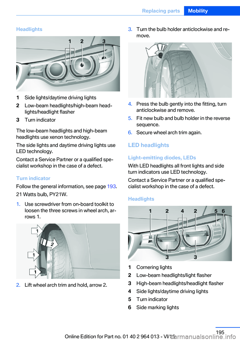
Headlights1Side lights/daytime driving lights2Low-beam headlights/high-beam head‐
lights/headlight flasher3Turn indicator
The low-beam headlights and high-beam
headlights use xenon technology.
The side lights and daytime driving lights use
LED technology.
Contact a Service Partner or a qualified spe‐
cialist workshop in the case of a defect.
Turn indicator
Follow the general information, see page 193.
21 Watts bulb, PY21W.
1.Use screwdriver from on-board toolkit to
loosen the three screws in wheel arch, ar‐
rows 1.2.Lift wheel arch trim and hold, arrow 2.3.Turn the bulb holder anticlockwise and re‐
move.4.Press the bulb gently into the fitting, turn
anticlockwise and remove.5.Fit new bulb and bulb holder in the reverse
sequence.6.Secure wheel arch trim again.
LED headlights
Light-emitting diodes, LEDs
With LED headlights all front lights and side
turn indicators use LED technology.
Contact a Service Partner or a qualified spe‐
cialist workshop in the case of a defect.
Headlights
1Cornering lights2Low-beam headlights/light flasher3High-beam headlights/headlight flasher4Side lights/daytime driving lights5Turn indicator6Side marking lightsSeite 195Replacing partsMobility195
Online Edition for Part no. 01 40 2 964 013 - VI/15
Page 196 of 228
In the event of a defect, contact the Service
Centre.
Turn indicator in exterior mirror Turn indicators in the exterior mirrors are de‐
signed in the LED technology. Contact a Serv‐
ice Partner or a qualified specialist workshop in
the case of a defect.
Rear lights, replacing the bulbs
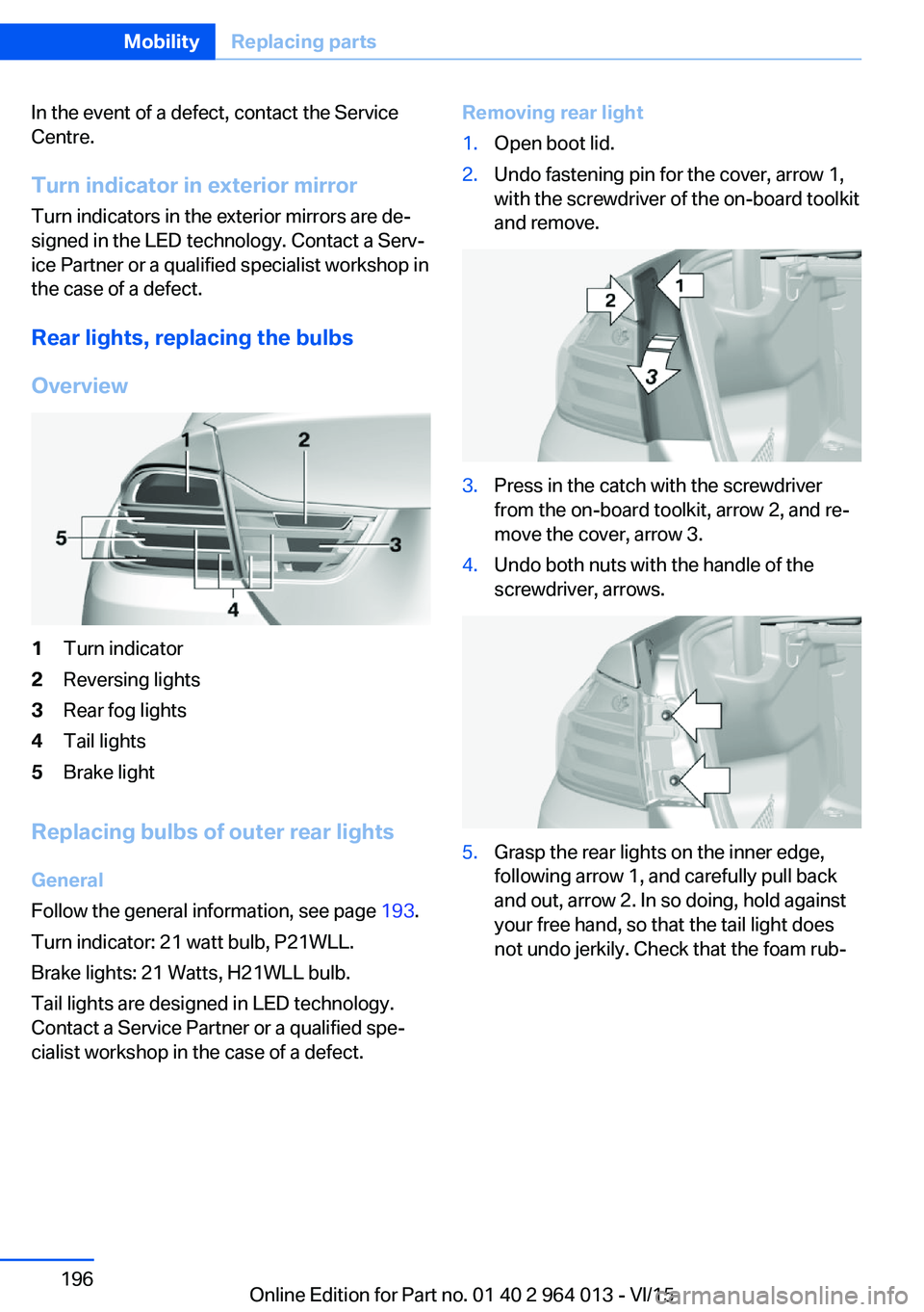
Overview1Turn indicator2Reversing lights3Rear fog lights4Tail lights5Brake light
Replacing bulbs of outer rear lights
General
Follow the general information, see page 193.
Turn indicator: 21 watt bulb, P21WLL.
Brake lights: 21 Watts, H21WLL bulb.
Tail lights are designed in LED technology.
Contact a Service Partner or a qualified spe‐
cialist workshop in the case of a defect.
Removing rear light1.Open boot lid.2.Undo fastening pin for the cover, arrow 1,
with the screwdriver of the on-board toolkit
and remove.3.Press in the catch with the screwdriver
from the on-board toolkit, arrow 2, and re‐
move the cover, arrow 3.4.Undo both nuts with the handle of the
screwdriver, arrows.5.Grasp the rear lights on the inner edge,
following arrow 1, and carefully pull back
and out, arrow 2. In so doing, hold against
your free hand, so that the tail light does
not undo jerkily. Check that the foam rub‐Seite 196MobilityReplacing parts196
Online Edition for Part no. 01 40 2 964 013 - VI/15