2016 BMW M4 light
[x] Cancel search: lightPage 197 of 228

ber sealing ring on the linkage of the cen‐
tring is plugged in.6.Undo upper rest on the plug of the con‐
necting cable and remove plug from the
bulb holder.
Replacing bulbs
1.Undo the three fastenings, arrow 1, on the
bulb holder and remove the bulb holder
from the tail light, arrow 2.2.Press the faulty bulb gently into the fitting,
turn anticlockwise and remove.3.To use the new bulb and attach the bulb
holder, proceed in the opposite sequence.
Ensure that the bulb holder engages in all
fastenings.
Installing rear light
1.Connect the connecting cable to the tail
light and fix into the bracket of the bulb
holder.2.Ensure that the foam rubber sealing ring
on the linkage of the centring, arrow 2, is
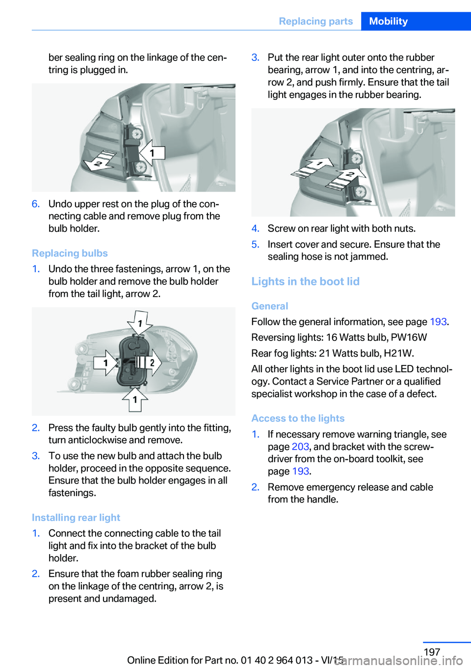
present and undamaged.3.Put the rear light outer onto the rubber
bearing, arrow 1, and into the centring, ar‐
row 2, and push firmly. Ensure that the tail
light engages in the rubber bearing.4.Screw on rear light with both nuts.5.Insert cover and secure. Ensure that the
sealing hose is not jammed.
Lights in the boot lid
General
Follow the general information, see page 193.
Reversing lights: 16 Watts bulb, PW16W
Rear fog lights: 21 Watts bulb, H21W.
All other lights in the boot lid use LED technol‐
ogy. Contact a Service Partner or a qualified
specialist workshop in the case of a defect.
Access to the lights
1.If necessary remove warning triangle, see
page 203, and bracket with the screw‐
driver from the on-board toolkit, see
page 193.2.Remove emergency release and cable
from the handle.Seite 197Replacing partsMobility197
Online Edition for Part no. 01 40 2 964 013 - VI/15
Page 198 of 228

3.Undo the fastenings of the trim with the
screwdriver from the on-board toolkit and
pull out completely.4.Push together hinged cover, see arrows, to
undo the clips.
Firmly hold cover and pull hinged cover
down and remove.5.Carefully remove the trim from the boot lid,
first on the edge and then in the area of the
recessed handles. Ensure that the trim
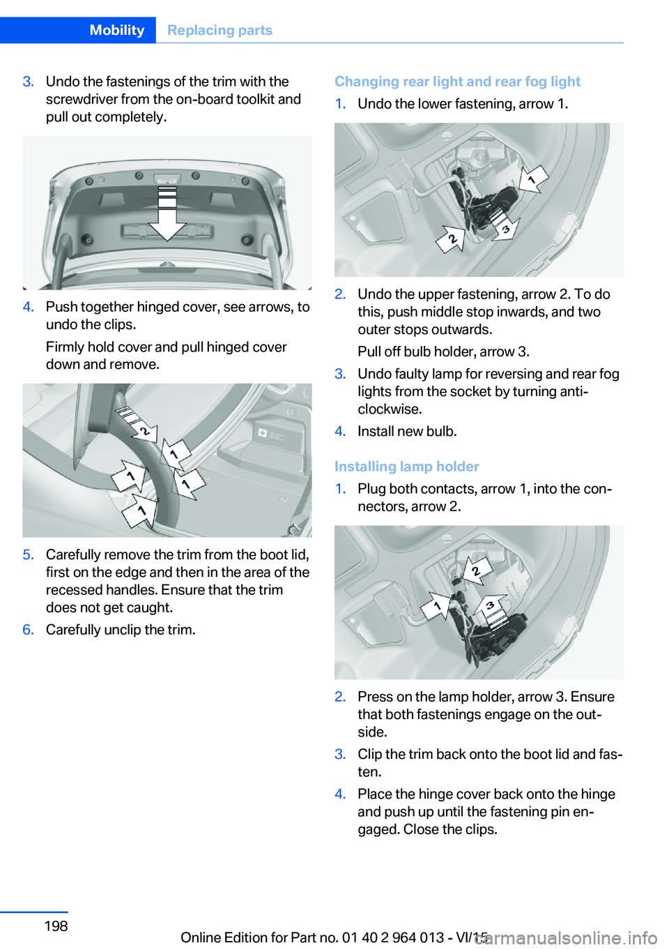
does not get caught.6.Carefully unclip the trim.Changing rear light and rear fog light1.Undo the lower fastening, arrow 1.2.Undo the upper fastening, arrow 2. To do
this, push middle stop inwards, and two
outer stops outwards.
Pull off bulb holder, arrow 3.3.Undo faulty lamp for reversing and rear fog
lights from the socket by turning anti-
clockwise.4.Install new bulb.
Installing lamp holder
1.Plug both contacts, arrow 1, into the con‐
nectors, arrow 2.2.Press on the lamp holder, arrow 3. Ensure
that both fastenings engage on the out‐
side.3.Clip the trim back onto the boot lid and fas‐
ten.4.Place the hinge cover back onto the hinge
and push up until the fastening pin en‐
gaged. Close the clips.Seite 198MobilityReplacing parts198
Online Edition for Part no. 01 40 2 964 013 - VI/15
Page 199 of 228

5.Install the cable on the handle of the emer‐
gency release and engage the handle into
the fastening.6.Fit the bracket for the warning triangle.7.Attach the warning triangle.
Tail lights, number plate lights and
centre brake light
These lights use LED technology. Contact a
Service Partner or a qualified specialist work‐
shop in the case of a defect.
Changing a wheel
Notes
When using sealants, immediate wheel change
in the event of loss of tyre pressure in case of
puncture is not required.
As a result, no spare wheel is available.
The tools for changing wheels are available as
optional accessories from a Service Partner or
a qualified specialist workshop.
Jack mounting points
The jack mounting points are located in the il‐
lustrated positions.
Thiefproof wheel studs
The adapter of the thiefproof wheel studs can
be found in the tool kit or in an oddments tray
in the tool kit.
▷Wheel stud, arrow 1.▷Adapter, arrow 2.
Removing
1.Place the adapter on the wheel stud.2.Unscrew wheel stud.
After reattaching the wheel stud, remove the
adapter again.
Car battery Maintenance
The battery is maintenance-free.
More information regarding the battery can be
enquired with a Service Partner or a qualified
specialist workshop.
Replacing the battery ATTENTION
Vehicle batteries that have been categor‐
ised by the manufacturer of the vehicle as un‐
suitable can damage systems, or prevent func‐
tions from being carried out. Danger of
damage to property. Only use vehicle batteries
that have been classified as suitable by the ve‐
hicle manufacturer.◀
When the vehicle battery has been changed,
have the battery registered on the vehicle by a
Service Partner or a qualified specialist work‐
shop to ensure that all comfort functions are
fully available and any appropriate Check Con‐
trol messages are no longer displayed.
Seite 199Replacing partsMobility199
Online Edition for Part no. 01 40 2 964 013 - VI/15
Page 202 of 228

Help in the event of a breakdownVehicle equipment
This chapter describes all standard, national
and special equipment provided in the model
series. Equipment not available in the vehicle is
therefore also described, for example the se‐
lected special equipment or national version.
This also applies to safety-relevant functions
and systems. Comply with the relevant na‐
tional regulations when using the correspond‐
ing functions and systems.
Hazard warning lights
The button is located in the centre console.
Intelligent emergency call
Principle This system can be used for sending an emer‐
gency call in emergency situations.
General Press the SOS button in an emergency only.
Even if no emergency call through BMW is
possible, in some cases an emergency call may still be set up to a public emergency call
number. This depends on factors such as the
specific mobile telephone network and the na‐
tional regulations.
For technical reasons, it might not be possible
to make an emergency call in highly adverse
conditions.
Overview
SOS button in headlining
Requirements
▷SIM card integrated into the vehicle is acti‐
vated.▷Radio ready state is switched on.▷Emergency call system is functional.
Making an emergency call
1.Briefly press the cover flap to open it.2.Press the SOS button until the LED on the
button is illuminated green.▷LED illuminated green: emergency call ac‐
tivated.
If a cancellation request is shown on the
display, the emergency call can be cancel‐
led.
If the situation permits, wait in the vehicle
until voice contact has been established.▷LED flashes green when the connection to
the emergency number has been estab‐
lished.
When an emergency call is sent via BMW,
data is sent to the emergency call centre in
order to decide what rescue measures areSeite 202MobilityHelp in the event of a breakdown202
Online Edition for Part no. 01 40 2 964 013 - VI/15
Page 204 of 228

3.Switch off any electrical systems in both
vehicles.
Jump-starting connections
WARNING
Connecting the jump leads in the wrong
sequence can cause sparks. Danger of injury.
Comply with the correct sequence when con‐
necting up.◀
The jump-starting connection in the engine
compartment serves as the positive battery
terminal.
Open the cover of the starting assistance con‐
nection.
The battery negative terminal is the body earth
or a special nut.
Connecting the cables
1.Open the cover of the BMW starting assis‐
tance connection.2.Connect a terminal clamp on the positive/+
jump lead to the positive terminal of the
battery or the corresponding jump-starting
connection on the donor vehicle.3.Connect the other terminal clamp to the
battery's positive terminal or to the corre‐
sponding jump-starting connection on the
vehicle to be started.4.Connect a terminal clamp on the negative/–
jump lead to the negative terminal of the
battery or the corresponding engine or
body earth connection on the donor vehi‐
cle.5.Connect the second terminal clamp to the
negative terminal of the battery or to a
ground/earth connection on the corre‐
sponding engine or body of the vehicle to
be started.
Starting the engine
Do not use the spray products sold as starting
aids.
1.Start the engine of the donor vehicle and
allow it to run for a few minutes at a slightly
increased idle speed.2.Start the engine of the vehicle to be started
as normal.
If an initial attempt to start the engine fails,
wait several minutes until the flat battery
has been recharged to a slightly greater
degree.3.Allow both engines to run for a few mi‐
nutes.4.Disconnect the jump leads in the opposite
order from that in which they were origi‐
nally attached.
Check the battery if necessary and have it re‐
charged.
Tow-starting and towing Information WARNING
Due to system limitations, there may be
malfunctions of individual functions when tow-
starting/towing with activated Intelligent Safety
Seite 204MobilityHelp in the event of a breakdown204
Online Edition for Part no. 01 40 2 964 013 - VI/15
Page 205 of 228

Systems, for example approach control warn‐
ing with light braking function. Danger of acci‐
dents. Switch off all Intelligent Safety Systems
before tow-starting/towing.◀
Manual gearboxGearshift lever in idle position.
Being towed Observe the following information:▷Make sure that the ignition is switched on,
otherwise low-beam headlights, rear lights,
turn indicators and wipers would not be
available.▷Do not tow the vehicle with the rear axle
raised, otherwise the steering can turn.▷When the engine is not running, there is no
power assistance and the brake servo is
out of action. The steering and brakes will
require extra effort to operate.▷Greater steering wheel movements are
necessary.▷The towing vehicle must not be lighter
than the towed vehicle, otherwise it may be
unable to keep the towed vehicle reliably
under control.▷Do not exceed a towing speed of on
50 km/h, 30 mph.▷Do not exceed a towing distance of 50 km,
30 miles.Towing truck
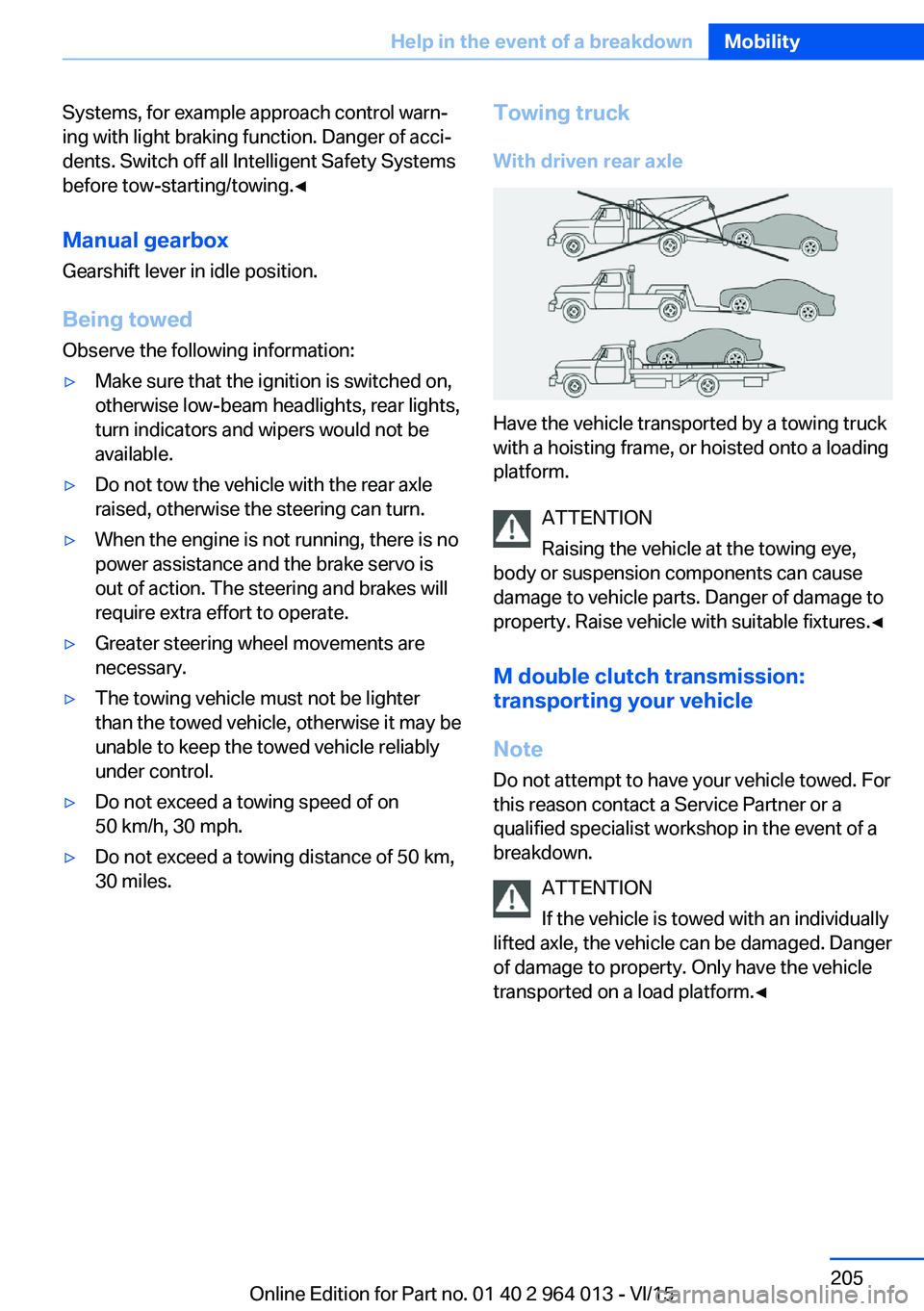
With driven rear axle
Have the vehicle transported by a towing truck
with a hoisting frame, or hoisted onto a loading
platform.
ATTENTION
Raising the vehicle at the towing eye,
body or suspension components can cause
damage to vehicle parts. Danger of damage to
property. Raise vehicle with suitable fixtures.◀
M double clutch transmission:
transporting your vehicle
Note
Do not attempt to have your vehicle towed. For
this reason contact a Service Partner or a
qualified specialist workshop in the event of a
breakdown.
ATTENTION
If the vehicle is towed with an individually
lifted axle, the vehicle can be damaged. Danger
of damage to property. Only have the vehicle
transported on a load platform.◀
Seite 205Help in the event of a breakdownMobility205
Online Edition for Part no. 01 40 2 964 013 - VI/15
Page 206 of 228

Towing truck
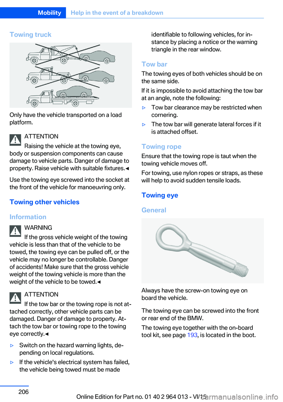
Only have the vehicle transported on a load
platform.
ATTENTION
Raising the vehicle at the towing eye,
body or suspension components can cause
damage to vehicle parts. Danger of damage to
property. Raise vehicle with suitable fixtures.◀
Use the towing eye screwed into the socket at
the front of the vehicle for manoeuvring only.
Towing other vehicles
Information WARNING
If the gross vehicle weight of the towing
vehicle is less than that of the vehicle to be
towed, the towing eye can be pulled off, or the
vehicle may no longer be controllable. Danger
of accidents! Make sure that the gross vehicle
weight of the towing vehicle is more than the
weight of the vehicle to be towed.◀
ATTENTION
If the tow bar or the towing rope is not at‐
tached correctly, other vehicle parts can be
damaged. Danger of damage to property. At‐
tach the tow bar or towing rope to the towing
eye correctly.◀
▷Switch on the hazard warning lights, de‐
pending on local regulations.▷If the vehicle's electrical system has failed,
the vehicle being towed must be madeidentifiable to following vehicles, for in‐
stance by placing a notice or the warning
triangle in the rear window.
Tow bar
The towing eyes of both vehicles should be on
the same side.
If it is impossible to avoid attaching the tow bar
at an angle, note the following:
▷Tow bar clearance may be restricted when
cornering.▷The tow bar will generate lateral forces if it
is attached offset.
Towing rope
Ensure that the towing rope is taut when the
towing vehicle moves off.
For towing, use nylon ropes or straps, as these
will help to avoid sudden tensile loads.
Towing eye
General
Always have the screw-on towing eye on
board the vehicle.
The towing eye can be screwed into the front
or rear end of the BMW.
The towing eye together with the on-board
tool kit, see page 193, is located in the boot.
Seite 206MobilityHelp in the event of a breakdown206
Online Edition for Part no. 01 40 2 964 013 - VI/15
Page 207 of 228

NotesATTENTION
If the towing eye is not used as intended,
the vehicle or towing eye is damaged. Danger
of damage to property. Observe the notes on
using the towing eye.◀
Using the towing eye:▷Use only the towing eye supplied with the
vehicle, and make sure that it is screwed in
fully and is tight.▷Only use the towing eye for towing on nor‐
mal roads (in other words not off-road).▷Use the towing eye screwed into the
socket at the front of the vehicle for ma‐
noeuvring only.▷Avoid lateral loads on the towing eye, for
example do not raise the vehicle at the
towing eye.
Thread for towing eye
Press the marking on the front cover to press it
out.
Use the screwdriver from the on-board toolkit
to press out the rear cover at the opening.
Tow-starting
M double clutch transmission Do not attempt to tow-start or push-start the
vehicle.
Due to the M double clutch transmission it is
not possible to start the engine by towing.
Have the cause of the starting difficulties recti‐
fied.
Manual gearbox If possible, do not tow-start the vehicle but
start the engine using starting assistance, see
page 203. Only tow-start when the engine is
cold if your vehicle has a catalytic converter.1.Switching on hazard warning lights, please
observe country-specific regulations.2.Ignition, see page 65, on.3.Insert 3rd gear.4.Tow-start with the clutch depressed and
release the clutch slowly. Depress the
clutch again immediately after the engine
starts.5.Stop in a suitable location, remove the tow
bar or towing rope and switch off the haz‐
ard warning lights.6.Have the vehicle checked.Seite 207Help in the event of a breakdownMobility207
Online Edition for Part no. 01 40 2 964 013 - VI/15