Page 177 of 208

CAUTION■“Never repair” fuses, and do not replace them with fuses of a higher amper-
age – risk of fire! This may also cause damage at other points in the electrical
system.■
If a newly inserted fuse blows again after a short time, have the electrical
system checked as quickly as possible by a specialist garage.
■
A blown fuse is recognisable by the molten metal strip. Replace the faulty
fuse with a new one of the same amperage.
Note
■
We recommend always carrying replacement fuses in the vehicle. A box of
replacement fuses and bulbs can be purchased from ŠKODA Genuine Accesso-
ries.■
There can be several power-consuming devices for one fuse.
■
Multiple fuses may exist for a single power-consuming device.
Fuses in the dash panel
Fig. 183
Remove the fuse box cover.
Read and observe and on page 174 first.
The fuses are located on the bottom of the dash panel behind a cover.
Replacing fuses
›
Grip the fuse box cover at point
A
and take-out in the direction of arrow
» Fig. 183 .
›
Remove the plastic clip from the holder in the fuse box cover.
›
Place the clip on the respective fuse and pull this fuse out.
›
Insert a new fuse.
›
Replace the bracket at the original position.
›
Insert the top edge of the cover into the dash panel first.
Carefully push the cover in.
Assignment of the fuses in the dash panelFig. 184
Schematic representation of the fuse box for vehicles with left-
hand steering/right-hand steering
Read and observe
and on page 174 first.
No.Power consumer1Left light2Central locking system3Relay for ignition4Right light5Power windows - driver6Central control unit - interior lights7Horn8Towing hitch - left light
9
Operating lever beneath the steering wheel, engine control unit (on-
ly without KESSY), automatic gearbox (only without KESSY), selector
lever of the automatic transmission (only without KESSY), ESC (only
without KESSY), towing equipment (only without KESSY), power
steering (only without KESSY)10Power windows - rear left11Headlight cleaning system12Radio, navigation display13Taxi preparation14Operating lever under the steering wheel, light switch, ignition key
removal lock (automatic gearbox), headlight flasher, SmartGate, rain
sensor 175Fuses and light bulbs
Page 178 of 208

No.Power consumer15Air conditioning system, selector lever of the automatic gearbox, di-
agnosis terminal16Instrument cluster17Alarm system, horn18Not assigned19Not assigned20Not assigned21Not assigned22Front- and rear windscreen wiper system23Heated front seats24Blower fan for air conditioning system, heating, air conditioning,
heating25Not assigned26Switch for front seat heating27Rear window wiper28Not assigned29airbag30Electric power windows, light switches, reverse light switches, air
conditioning system, Park Assist, exterior mirror, power feed for cen-
tre button strip, power feed for side button strip, interior mirror31Fuel pump, radiator fan, cruise control, coil of the relay for the front
and rear windscreen wipers32Diagnostic terminal, headlight range control, operating lever under
the steering wheel, interior lighting33Coil on starter relay, clutch pedal switch34Heated windscreen washer jets35Not assigned36Not assigned37Radar38Not assigned39Electrical auxiliary heating system40Not assigned41Rear window heaterNo.Power consumer42Power windows - front passenger43Towing hitch - contact in the socket44Cigarette lighter, 12-volt power socket45Power windows - rear right46Front and rear window washer, operating lever under the steering
wheel47Towing hitch - contact in the socket48Towing hitch - right light49Fuel pump50Radio51Heating of the external mirror52KESSY53Steering lock (KESSY)54ABS or ESC55Not assigned56Not assigned57Not assigned58Not assigned59Not assigned
Fuses in the engine compartment
Fig. 185
Cover for the fuse box - variant 1
176Do-it-yourself
Page 179 of 208

Fig. 186
Cover for the fuse box - variant 2
Read and observe
and on page 174 first.
Replacing fuses
›
Press the lock button on the cover in direction of arrow
1
» Fig. 185 or
» Fig. 186 .
›
Raise the cover and remove in the direction of the arrow
2
.
›
Remove the plastic clip from the holder in the fuse box cover.
›
Replace the appropriate fuse.
›
Replace the bracket at the original position.
›
Place the cover on top of the fuse box.
›
Push in the locking button on the cover and lock.
The cover must engage securely.
CAUTION
The cover for the fuse box in the engine compartment must always be re-
placed correctly. Water may get into the fuse box if the cover is not replaced
properly - there is a risk of damage to the vehicle!
Fuse assignment in the engine compartment
Fig. 187
Fuses
Read and observe and on page 174 first.No.Power consumer1Radiator fan2Glow plug system3ABS or ESC4Auxiliary electric heating - circuit 25Auxiliary electric heating - circuit 36Automatic gearbox7Engine control unit8Windscreen wipers9Central control unit, battery data module10ABS or ESC11Not assigned12Engine components13Brake pedal switch14Engine components, coil for the fuel pump relay, radiator fan, cooling
pump15Engine control unit16Starter17Engine control unit18Engine components, coils of the relay for auxiliary electric heater19Lambda probe20Glow plug system, crankcase ventilation heater
Replacing bulbs
Introduction
This chapter contains information on the following subjects:
Bulb arrangement in the headlights
178
Replacing the high beam bulb (halogen headlights)
179
Replacing bulb for main beam, daytime running lights and parking light
179
Changing the front turn signal bulb
180
Replacing the bulb for the fog light
180
177Fuses and light bulbs
Page 180 of 208

Replacing the bulb for the licence plate light181Rear Light181
Replacing bulbs in rear light
182
Some manual skills are required to change a bulb. For this reason, we recom-
mend having bulbs replaced by a specialist garage or seeking other expert help
in the event of any uncertainties.
▶ Switch off the ignition and the relevant lights before replacing a bulb.
▶ Faulty bulbs must only be replaced with the same type of bulbs. The designa-
tion is located on the light socket or the glass bulb.
A stowage compartment for replacement bulbs is located in a plastic box in
the spare wheel or underneath the floor covering in the boot.
We recommend having the headlight settings checked by a specialist garage
after replacing a bulb in the low, high or fog beam.
In case of failure of a xenon gas discharge lamp or an LED diode, visit a special- ist garage.
WARNING■ Always read and observe the warning notes before completing any work
in the engine compartment » page 143.■
Accidents can be caused if the road in front of the vehicle is not suffi-
ciently illuminated and the vehicle cannot or can only be seen with difficul-
ty by other road users.
■
H7 and H15 bulbs are pressurised and may burst when changing the bulb -
risk of injury! We therefore recommended wearing gloves and safety
glasses when changing a bulb.
■
Do not carry out any work on the Xenon gas discharge lamps - risk of
death!
CAUTION
■ Do not take hold of the glass bulb with naked fingers (even the smallest
amount of dirt reduces the working life of the light bulb). Use a clean cloth,
napkin, or similar.■
The protective cap of the bulb must always be properly inserted into the
headlamp. Water and dirt may get into the headlamp if the cover is not re-
placed properly - there is a risk of damage to the headlamp!
Note■ This Owner's Manual only describes the replacement of bulbs where it is pos-
sible to replace the bulbs on your own without any complications arising. Other
bulbs must be replaced by a specialist garage.■
We recommend that a box of replacement bulbs always be carried in the ve-
hicle. Replacement bulbs can be purchased from ŠKODAOriginal Accessories.
Bulb arrangement in the headlights
Fig. 188
Principle sketch: Headlights
Read and observe and on page 178 first.
Bulb arrangement » Fig. 188
Low beam or low beam with xenon gas discharge lamp
Main beam, separate daytime running lights, and parking light
Turn signal light (at the front)
ABC178Do-it-yourself
Page 181 of 208
Fig. 189
Changing the bulb for the low beam
Read and observe
and on page 178 first.
›
Remove the protective cap
A
» Fig. 188 on page 178 .
�")
Replacing the high beam bulb (halogen headlights)Fig. 189
Changing the bulb for the low beam
Read and observe
and on page 178 first.
›
Remove the protective cap
A
» Fig. 188 on page 178 .
›
Remove the socket with the bulb by jiggling it out in the direction of arrow
1
» Fig. 189 .
›
Remove the connector.
›
Insert the connector with the new bulb in the direction of arrow
2
so that
the fixing lug
A
fits the bulb into the recess on the reflector.
›
Attach the connector.
›
Fit the protective cap
A
» Fig. 188 on page 178 .
Replacing bulb for main beam, daytime running lights and parking
light
Fig. 190
Replacing the bulb for main
beam and separate daytime run-
ning lights
Fig. 191
Change the light bulb for the parking light
Read and observe
and on page 178 first.
Removing/replacing the bulb for main beam and separate daytime running
lights
›
Remove the protective cap
B
» Fig. 188 on page 178 .
›
Pull the holder until it stops in the arrow direction
1
» Fig. 190 .
›
Remove the socket with the bulb in the direction of arrow
2
.
›
Change the bulb in the socket.
›
Insert the socket with the new bulb into the headlight in the opposite direc-
tion to the arrow
2
.
›
Turn the socket with the new bulb in the opposite direction to the arrow
1
until it stops.
›
Fit protective cap
B
» Fig. 188 on page 178 Insert.
Removing/replacing the bulb for the parking light
›
Remove the protective cap
B
» Fig. 188 on page 178 .
›
Remove the bulb holder with the bulb by jiggling it out in the direction of the
arrow
1
» Fig. 191 .
›
Grasp the lamp socket at the places marked by arrows.
›
Remove the faulty bulb from the holder in the direction of the arrow
2
.
›
Insert a new bulb in the bulb holder up to the stop.
›
Replace the bulb holder in the headlamp with the bulb.
›
Fit protective cap
B
» Fig. 188 on page 178 Insert.
179Fuses and light bulbs
Page 182 of 208

Changing the front turn signal bulbFig. 192
Changing the bulb for the front
turn signal light
Read and observe and on page 178 first.
›
Turn the socket with the bulb in the direction of arrow
1
» Fig. 192 .
›
Remove the socket with the bulb in the direction of arrow
2
.
›
Change the bulb in the socket.
›
Insert the socket with the new bulb into the headlight in the opposite direc-
tion to the arrow
2
.
›
Turn the socket with the new bulb in the opposite direction to the arrow
1
until it stops.
Replacing the bulb for the fog lightFig. 193
Remove the number plate light / replace the bulb
Read and observe
and on page 178 first.
Remove the protective grille and headlight
›
Insert the clamps for removing the full wheel covers » page 161, Vehicle tool
kit into opening
A
» Fig. 193 .
›
Loosen the protective grille by pulling the hook in the direction of arrow
1
.
›
Remove the protective grille in the direction of the arrow
2
.
›
Unscrew the screws
B
with the screwdriver from the tool kit.
›
With the key
2
» page 161 , Vehicle tool kit unlock the locking
C
in direction
of arrow
3
.
›
Remove the headlight in the direction of arrow
4
.
Replacing the light bulb
›
Press the latch on the connector in the direction of arrow
5
.
›
Remove the key in the direction of the arrow
6
.
›
Pull the lamp holder until it stops in the arrow direction
7
.
›
Remove the lamp holder in the direction of the arrow
8
.
›
Insert the new bulb into the headlight and turn counter to the direction of
arrow
7
as far as the stop.
180Do-it-yourself
Page 183 of 208

›Attach the connector.
Refit the headlight and grille›
Replace the fog light by inserting it in the opposite direction of the arrow
4
» Fig. 193 and tightening.
›
Insert the protective grille and carefully press it in.
The protective grille must engage firmly.
Replacing the bulb for the licence plate light
Fig. 194
Remove the number plate light/replace the bulb
Read and observe
and on page 178 first.
›
Open the boot lid.
›
Push in the lamp in the direction of the arrow
1
» Fig. 194 .
The lamp comes loose.
›
Swivel out the lamp in the direction of the arrow
2
and remove it.
›
Remove the faulty bulb from the holder in the direction of the arrow
3
.
›
Insert a new bulb into the holder.
›
Reinsert the lamp in the opposite direction to the arrow
1
.
›
Push on the light until the spring clicks into place.
Check that the light is securely inserted.
Rear LightFig. 195
Remove light / pull out connector
Read and observe
and on page 178 first.
Removing
›
Open the boot lid.
›
Insert the clamps for removing the full wheel covers » page 161, Vehicle tool
kit into opening
A
» Fig. 195 .
›
Remove the cover by pulling the hook in the direction of arrow
1
.
›
Unscrew the screws
B
with the key from the tool kit.
›
Grasp the lamp and carefully remove in the direction of arrow
2
.
›
Press the latch on the connector in the direction of arrow
3
.
›
Carefully remove the connector from the tail lamp assembly in the direction
of the arrow
4
.
Fitting
›
Insert the bulb holder into the lamp.
The lock on the plug must be inserted securely.
›
Insert the lamp with the pin
B
» Fig. 196 on page 182 into the recesses
C
» Fig. 195 in the body.
181Fuses and light bulbs
Page 184 of 208

›Carefully push the cover in
» .›Screw the tail lamp into place and install the cover.
The cover must engage securely.
CAUTION
■ Ensure that the cable bundle does not become pinched between the body
and the lamp when it is being refitted – risk of damage to the electrical instal-
lation and risk of water ingress.■
If you are not sure whether the cable bundle has become pinched, we recom-
mend that you have the light connection checked by a specialist garage.
■
Ensure that the vehicle paintwork and the tail lamp are not damaged when
removing and installing the tail lamp.
Replacing bulbs in rear light
Fig. 196
Outer part of the lamp/inner part of the lamp
Read and observe
and on page 178 first.
Outer part of the lamp
›
Rotate the lamp socket
A
» Fig. 196 in direction of arrow
1
and remove in
direction of arrow
2
from the lamp housing.
›
Changing the lamp, reinsert the holder with the bulb into the lamp housing
and turn in the opposite direction of the arrow
1
to the stop.
Inner parts of the lamp
›
Unlock the bulb holder using the marked area with arrows » Fig. 196 and re-
move the bulb holder from the light.
›
Turn the respective bulb counter clockwise until it stops.
›
Remove the holder from the lamp.
›
Insert a new bulb into the holder and turn in a clockwise direction to the
stop.
› Insert the bulb holder in the tail lamp assembly.
The lamp holder must engage firmly.182Do-it-yourself
 1
1 2
2 3
3 4
4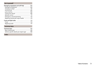 5
5 6
6 7
7 8
8 9
9 10
10 11
11 12
12 13
13 14
14 15
15 16
16 17
17 18
18 19
19 20
20 21
21 22
22 23
23 24
24 25
25 26
26 27
27 28
28 29
29 30
30 31
31 32
32 33
33 34
34 35
35 36
36 37
37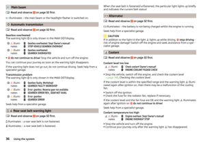 38
38 39
39 40
40 41
41 42
42 43
43 44
44 45
45 46
46 47
47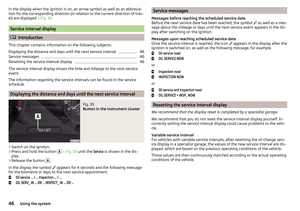 48
48 49
49 50
50 51
51 52
52 53
53 54
54 55
55 56
56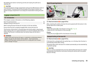 57
57 58
58 59
59 60
60 61
61 62
62 63
63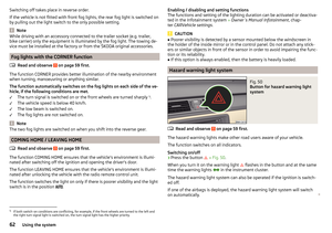 64
64 65
65 66
66 67
67 68
68 69
69 70
70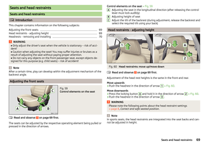 71
71 72
72 73
73 74
74 75
75 76
76 77
77 78
78 79
79 80
80 81
81 82
82 83
83 84
84 85
85 86
86 87
87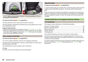 88
88 89
89 90
90 91
91 92
92 93
93 94
94 95
95 96
96 97
97 98
98 99
99 100
100 101
101 102
102 103
103 104
104 105
105 106
106 107
107 108
108 109
109 110
110 111
111 112
112 113
113 114
114 115
115 116
116 117
117 118
118 119
119 120
120 121
121 122
122 123
123 124
124 125
125 126
126 127
127 128
128 129
129 130
130 131
131 132
132 133
133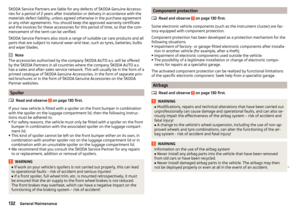 134
134 135
135 136
136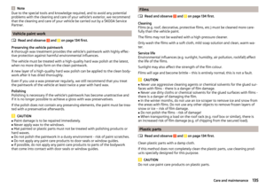 137
137 138
138 139
139 140
140 141
141 142
142 143
143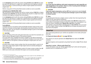 144
144 145
145 146
146 147
147 148
148 149
149 150
150 151
151 152
152 153
153 154
154 155
155 156
156 157
157 158
158 159
159 160
160 161
161 162
162 163
163 164
164 165
165 166
166 167
167 168
168 169
169 170
170 171
171 172
172 173
173 174
174 175
175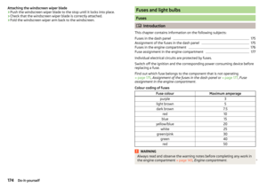 176
176 177
177 178
178 179
179 180
180 181
181 182
182 183
183 184
184 185
185 186
186 187
187 188
188 189
189 190
190 191
191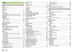 192
192 193
193 194
194 195
195 196
196 197
197 198
198 199
199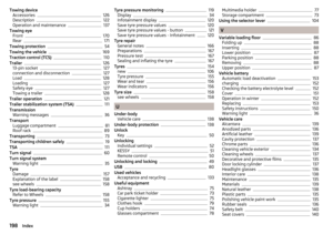 200
200 201
201 202
202 203
203 204
204 205
205 206
206 207
207