Page 89 of 208

Setting in the upper positionFig. 100
Set the variable loading floor to the upper position
The variable loading floor in the lower position can be set to the upper position
as follows.
›
Grasp the variable loading floor at handle
A
» Fig. 100 .
›
Lift the variable loading floor in the direction of arrow
1
and move partially
backwards in the direction of arrow
2
.
›
Lift the variable loading floor at the front, place onto corner
C
and slide in
the direction of arrow
3
until it clicks into place in brackets
B
.
›
Place the variable loading floor in direction of arrow
4
.
CAUTION
The variable loading floor cannot be set in the upper position when the lug-
gage compartment cover is in the “park position” » page 84.
Note
When in the upper position there is space for storing items underneath the
variable loading floor.Setting in the lower positionFig. 101
Set the variable loading floor to the lower position
The variable loading floor in the upper position can be set to the lower position
as follows.
›
Grasp the variable loading floor at handle
A
» Fig. 101 .
›
Lift the variable loading floor in the direction of arrow
1
and partially move
in the direction of arrow
2
until it detaches from brackets
B
.
›
Place the variable loading floor onto the floor covering of the luggage com-
partment while tilted forward.
›
Push the variable loading floor in the direction of arrow
3
as far as it will go,
and until its front part
C
is raised.
›
Place the variable loading floor in direction of arrow
4
.
CAUTION
The variable loading floor cannot be set in the lower position when the lug-
gage compartment cover is in the “park position” » page 84.87Transporting and practical equipment
Page 90 of 208

Removing/insertingFig. 102
Remove variable loading floor
Removing
›
Grasp the variable loading floor at handle
A
» Fig. 102 .
›
Lift the variable loading floor in the direction of arrow
1
until its rear area is
about 15 cm
B
below the luggage compartment cover » .
›
Remove the variable loading floor from the vehicle by moving it in the direc-
tion of arrow
2
.
Inserting
›
Grasp the variable loading floor at handle
A
» Fig. 102 .
›
Insert variable loading floor into the vehicle with the front portion tilted
about 15 cm
B
beneath the luggage compartment cover » .
›
Then follow the same steps as when setting the upper position » page 87 or
the lower position » page 87 .
CAUTION
■
When removing or inserting the variable loading floor, a distance of 15 cm B» Fig. 102 underneath the boot cover must be adhered to - risk of damaging
the boot lid seal.■
The variable loading floor cannot be placed in the vehicle when the luggage
compartment cover is in the “park position” » page 84.
■
After removing the variable cargo floor, place it down in such a way that it
cannot be damaged or soiled.
Folding up/downFig. 103
Fold up/fold down variable loading floor
The variable loading floor can be folded up in both positions (upper and lower).
Folding up
›
Grasp the variable loading floor at handle
A
» Fig. 103 .
›
Lift the variable loading floor in the direction of the arrow
1
until the folding
corners
B
lock into place in area
C
.
Folding down
›
Grasp the variable loading floor in the middle or at handle
A
» Fig. 103 .
›
Unlock the variable loading floor by pulling it in the direction of the arrow
2
.
“Parking position”
Fig. 104
Set parking position / fold down from the parking position
The variable loading floor can only be in set to the “parking position” when it is
in the lower position » page 87 and the luggage compartment cover has been
taken out » page 84.
88Using the system
Page 91 of 208

Folding up›Remove the luggage compartment cover from the vehicle » page 84.›
Grasp the variable loading floor at handle
A
» Fig. 104 .
›
Lift the variable loading floor in the direction of the arrow
1
until the folding
corners
B
lock into place in area
C
.
Folding down
›
Push the folding corners
B
» Fig. 104 on both sides of the variable loading
floor in the direction of the arrow
2
and release these from positions
C
.
›
Grasp the variable loading floor in the middle or at handle
A
.
›
Fold down the variable loading floor in the direction of arrow
3
.
WARNINGThe variable loading floor in the “parking position” restricts the driver's
view at the back.
CAUTION
■ The variable loading floor can only be in set to the “parking position” when it
is in the lower position and the luggage compartment cover has been taken
out.■
If the variable loading floor is in the “parking position”, the “parking position”
on the luggage compartment cover cannot be set » page 84.
Roof rack
Introduction
This chapter contains information on the following subjects:
fixing points for base support
89
Roof load
90WARNINGWhen transporting cargo the following the instructions must be adhered
to.■
The items being transported on the roof rack must always be securely at-
tached – risk of accident!
■
Always secure the load with appropriate and undamaged lashing straps
or tensioning straps.
■
Distribute the load evenly over the roof rack system.
WARNING (Continued)■ When transporting heavy objects or objects which take up a large area on
the roof rack system, handling of the car may change as a result of the dis-
placement of the centre of gravity. The style of driving and speed must
therefore be adapted to the current circumstances.■
Avoid abrupt and sudden driving/braking manoeuvres.
■
The permissible roof load, permissible axle loads and permissible total ve-
hicle weight must not be exceeded under any circumstance – risk of acci-
dent!
CAUTION
■ On models fitted with an electrical sliding/tilting roof, ensure that the slid-
ing/tilting roof does not strike any items of luggage transported on the roof
when tilting.■
Ensure that the boot lid does not hit the roof load when opened.
■
The height of the vehicle changes after mounting a roof luggage rack system
including the load that is being transported. Compare the vehicle height with
available clearances, such as underpasses and garage doors.
■
Ensure the roof aerial is not impaired by the load being transported.
Note
We recommend that you use a roof rack from ŠKODA Original Accessories.
fixing points for base support
Fig. 105
Attachment points
Read and observe
and on page 89 first.
The mounting points are located on both sides of the vehicle.
89Transporting and practical equipment
Page 92 of 208

Arrangement of the mounting points » Fig. 105
Front attachment points
Rear attachment points
The mounting and dismounting of the basic carrier is carried out according to the instructions provided.
Roof load
Read and observe
and on page 89 first.
Do not exceed the permissible roof load of 75 kg, this includes the carrier sys-
tem.
The full permissible roof load cannot be used if a roof rack system with a lower
load carrying capacity is used. The maximum capacity of the carrier system
should never be exceeded.
ABHeating and ventilation
Heating, manual air conditioning system, Climatronic
Introduction
This chapter contains information on the following subjects:
Heating and manual air conditioning
91
Climatronic (automatic air conditioning)
92
Climatronic - automatic mode
93
Air distribution control
93
Air outlet vents
94
The heating and air conditioning ventilate and heat the vehicle interior. The air
conditioning system also cools and dehumidifies the vehicle interior.
The heating effect is dependent upon the coolant temperature, thus full heat
output only occurs when the engine has reached its operating temperature.
The cooling system only operates if the following conditions are met. The cooling system is switched on.
The engine is running.
The outside temperature is above approx. +2 °C.
The blower is switched on.
If the cooling system is switched on, the temperature and air humidity drops in the vehicle. The cooling system prevents the windows from misting up during
winter months.
It is possible to briefly activate re-circulated air mode to enhance the cooling
effect » page 93 .
Health protection
To reduce health risks (e.g. common colds), the following instructions for the
use of the cooling system are to be observed. ▶ The difference between the indoor temperature and the outdoor air temper-
ature should not be greater than about 5 ° C.
▶ The cooling system is to be turned off about 10 minutes before the end of
the journey.
▶ Once a year, disinfection of the manual air conditioner or the Climatronic is to
be carried out by a specialist company.
90Using the system
Page 93 of 208

WARNING■For your own safety and that of other road users, ensure that all the win-
dows are free of ice, snow and misting. The blower should always be on to
prevent the windows from misting up.■
Under certain circumstances, air at a temperature of about 5 °C can flow
out of the vents when the cooling system is switched on.
CAUTION
■ The air inlet in front of the windscreen must be free from ice, snow or leaves,
for example, to ensure that the heating and cooling system works properly.■
After switching on the cooling Condensation from the evaporator of the air
conditioning may drip down and form a puddle below the vehicle. This is not a
leak!
■
If the coolant temperature is too high, the cooling system is switched off to
ensure that the engine cools down.
Heating and manual air conditioning
Fig. 106
Heating Controls
Fig. 107
Controls of the manual air conditioning
Read and observe
and on page 91 first.
Individual functions can be set or switched on by turning the rotary switch or
pressing the respective button. When the function is switched on, the indica-
tor light in the button lights up.
Functions of the individual control elements » Fig. 106 and » Fig. 107
Set the temperature
▶ Lower the temperature
▶ Increase the temperature
Set the blower speed (Level 0: Fan off, Level 4: Highest speed)
Set the direction of the air outlet » page 94
▶ Air flow to the windows
▶ Air flow to the upper body
▶ Air flow to the footwell
▶ Air flow to the windows and the footwell
Switch recirculation on/off » page 93
Switch the cooling system on/off
Information on the cooling system
The cooling system operates only if the following conditions are met
» page 90 .
The warning light in the button
» Fig. 107 lights up after activation, even if
not all of the conditions for the function of the cooling system have been met.
By lighting up of the warning light in the button, the operational readiness of
the cooling system is signalled.
ABC91Heating and ventilation
Page 94 of 208

NoteDuring operation of the manual air conditioning, an increase in engine idle
speed may occur under certain circumstances in order to ensure sufficient
heating comfort.
Climatronic (automatic air conditioning)
Fig. 108
Controls the Climatronic
Read and observe
and on page 91 first.
The Climatronic in automatic mode ensures the best-possible setting of the
temperature of the out-flowing air, the blower stage and air distribution.
Individual functions can be set or switched on by turning the rotary switch or
pressing the respective button. When this function is switched on, the corre-
sponding icon appears in the display.
Functions of the individual control elements and display indicators » Fig. 108
Set the temperature
▶ Lower the temperature
▶ Increase the temperature
Selected temperature
Degrees Celsius or Fahrenheit
Automatic operation of the air conditioning system is switched on
Intensive windshield defroster switched on
Direction of air flow
Recirculated air mode activated
Cooling system activated
Set blower speed
123456789Set the blower speed (the set blower speed is indicated by the corre-
sponding number of segments in the display)
▶ Turn to the left: Reduce speed up to turning off the Climatronic
▶ Turn to the right: Increase speed
Interior temperature sensor Switching the intensive windshield defroster on/off - when this function
is switched on, the warning light illuminates in the button
Switching automatic mode on
Switching the airflow to the windows on and off
Switching the airflow to the upper body on and off
Switching the airflow to the footwell on and off
Switch recirculation on/off » page 93
Switch the cooling system on/off
After the cooling system is switched off, only the ventilation function remains active, whereby the lowest temperature that can be reached is the outside
temperature.
Setting temperature
The temperature can be set between +16 °C and +29 °C. The temperature is
regulated automatically within this range.
If illuminates in the display, then the Climatronic is working with
maximum
cooling (temperature setting below +16°C).
If illuminates in the display, then the Climatronic is working with
maximum
heating (temperature setting above +29°C).
There is no automatic temperature control in the two end positions.
Switching between Celsius and Fahrenheit
Press buttons and
simultaneously and hold for about 2 seconds.
The desired temperature unit (item 3
» Fig. 108 ) appears on the display.
WARNING■
Do not switch off the Climatronic system for longer than necessary.■Switch on the Climatronic system as soon as the windows mist up.
CAUTION
Do not cover the interior temperature sensor 11 » Fig. 108 as this could impair
the functioning of the Climatronic. 101192Using the system
Page 95 of 208

Note■As soon as the windscreen mists up, press the symbol button . Press the
button once the windscreen has demisted.■
During operation of the Climatronic, an increase in engine idle speed can oc-
cur under certain circumstances in order to ensure adequate heating comfort.
Climatronic - automatic mode
Read and observe
and on page 91 first.
The automatic mode is used in order to maintain a constant temperature andto demist the windows in the interior of the car.
To switch on press the
button. The display shows
(pos.
4
» Fig. 108
on page 92 ).
Automatic mode can be switched off by pressing one of the buttons for the air
distribution or by increasing/decreasing the blower speed. The temperature is
nevertheless regulated.
Air distribution control
Read and observe
and on page 91 first.
The recirculation mode prevents contaminated outside air getting into the In-terior of the vehicle.
In recirculated air mode air is sucked out of the interior of the vehicle and then
fed back into the interior.
Switching on/off
›
Press the button.
Heating and manual air conditioning system
If the air distribution control is set to position when the recirculation modes
is switched on, the recirculated-air mode is switched off. Recirculated air mode
can be switched on again from this setting by repeatedly pressing the symbol
button .
Climatronic
With the recirculated-air mode switched on the symbol appears in the dis-
play.
The symbol disappears from the display after turning off the air recircula-
tion.
Depending on the moisture conditions in the vehicle interior the air recircula-
tion may shut-down automatically.WARNINGThe recirculation system cannot be switched on for a longer period of time,
because there is no supply of fresh air from the outside. “Stale air” may re-
sult in fatigue in the driver and occupants, reduce attention levels and also
cause the windows to mist up. The risk of having an accident increases.
Switch off recirculated air mode as soon as the windows start to mist up.
CAUTION
We recommend not smoking in the vehicle when the recirculating air operation
is switched on. The smoke sucked from inside the vehicle is deposited on the
evaporator of the air conditioner. This produces a permanent odour when the
air conditioning system is operating which can only be eliminated through con-
siderable effort and expense (replacement of compressor).
Note
If recirculated air mode is switched on for around 15 minutes, the symbol
will begin to flash in the Climatronic display as a sign that the recirculated air
mode is switched on long-term. If the recirculated air mode is not switched off,
the symbol flashes for around 5 minutes.93Heating and ventilation
Page 96 of 208

Air outlet ventsFig. 109
Air outlet vents
Read and observe
and on page 91 first.
The direction of airflow can be adjusted using the air outlet vents 3, 4
» Fig. 109 , the outlets can be opened and closed individually.
Changing the direction of air flow
›
To change the height of the air flow, turn the horizontal fins upward or
downward using the movable adjuster
A
» Fig. 109 .
›
To adjust the lateral direction of the air flow, turn the vertical fins with the
movable adjuster
A
to the left or to the right.
Opening
›
Turn the regulator
B
upwards » Fig. 109 .
Closing
›
Turn the regulator
B
downwards » Fig. 109.
Overview of the available settings for adjusting the direction of the air outlet
Set the direction of the air outletActive air vents » Fig. 1091, 2 , 41, 2 , 4 , 5Set the direction of the air
outletActive air vents » Fig. 1093, 44 , 5
CAUTION
To ensure that the heating, the manual air conditioning and the Climatronic
systems work properly, do not block up the air outlet vents with any objects.94Using the system
 1
1 2
2 3
3 4
4 5
5 6
6 7
7 8
8 9
9 10
10 11
11 12
12 13
13 14
14 15
15 16
16 17
17 18
18 19
19 20
20 21
21 22
22 23
23 24
24 25
25 26
26 27
27 28
28 29
29 30
30 31
31 32
32 33
33 34
34 35
35 36
36 37
37 38
38 39
39 40
40 41
41 42
42 43
43 44
44 45
45 46
46 47
47 48
48 49
49 50
50 51
51 52
52 53
53 54
54 55
55 56
56 57
57 58
58 59
59 60
60 61
61 62
62 63
63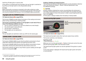 64
64 65
65 66
66 67
67 68
68 69
69 70
70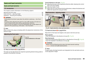 71
71 72
72 73
73 74
74 75
75 76
76 77
77 78
78 79
79 80
80 81
81 82
82 83
83 84
84 85
85 86
86 87
87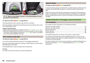 88
88 89
89 90
90 91
91 92
92 93
93 94
94 95
95 96
96 97
97 98
98 99
99 100
100 101
101 102
102 103
103 104
104 105
105 106
106 107
107 108
108 109
109 110
110 111
111 112
112 113
113 114
114 115
115 116
116 117
117 118
118 119
119 120
120 121
121 122
122 123
123 124
124 125
125 126
126 127
127 128
128 129
129 130
130 131
131 132
132 133
133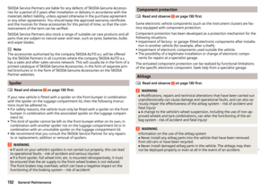 134
134 135
135 136
136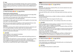 137
137 138
138 139
139 140
140 141
141 142
142 143
143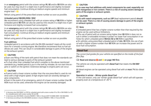 144
144 145
145 146
146 147
147 148
148 149
149 150
150 151
151 152
152 153
153 154
154 155
155 156
156 157
157 158
158 159
159 160
160 161
161 162
162 163
163 164
164 165
165 166
166 167
167 168
168 169
169 170
170 171
171 172
172 173
173 174
174 175
175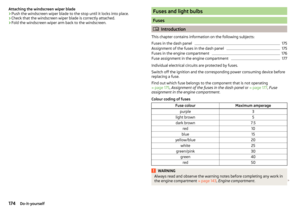 176
176 177
177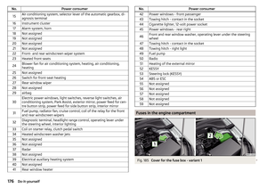 178
178 179
179 180
180 181
181 182
182 183
183 184
184 185
185 186
186 187
187 188
188 189
189 190
190 191
191 192
192 193
193 194
194 195
195 196
196 197
197 198
198 199
199 200
200 201
201 202
202 203
203 204
204 205
205 206
206 207
207