Page 121 of 208

Stop the car, switch off the engine and clean the sensor or eliminate the dis-
turbance causing the lack of visibility » Fig. 131 on page 116 .
If after engine start the message persists, then the help of a professional or-
ganisation is required.Front Assist not available.FRONT ASSIST NOT AVAILABLE
The system is not available for an unknown reason.
Stop the vehicle, switch off the engine and then start it again.
If after engine start the message persists, then the help of a professional or- ganisation is required.
Fatigue detection
Introduction
This chapter contains information on the following subjects:
Function
119
Information messages
119
The fatigue detection system (hereinafter referred to as the system) recom-
mends the driver takes a break from driving when driver fatigue can be detec-
ted due to the driver's steering behaviour.
WARNING■ The general information relating to the use of assistance systems must
be observed » page 109, in section Introduction .■
For the driving ability is always the driver's responsibility. Never drive if
you feel tired.
■
The system may not detect all cases where a break is needed.
■
Therefore, take regular, sufficient breaks during long trips.
■
There will be no system warning during the so-called micro-sleep.
Note
■ In some situations, the system may evaluate the driving incorrectly and thus
mistakenly recommend a break (e.g. sporty driving, adverse weather condi-
tions or poor road conditions).■
The system is designed primarily for use on motorways.
Function
Read and observe
on page 119 first.
From the start of the journey, the system evaluates steering behaviour. If,
while driving, there have been changes in the steering behaviours that are
evaluated by the system as indicating possible fatigue, a break recommenda-
tion is issued.
The system evaluates steering behaviour and recommends a break at speeds
of 65 - 200 km/h.
The system detects a break from driving when one of the following condi-
tions is met.
▶ The vehicle is stopped and the ignition switched off.
▶ The vehicle is stopped, the seat belt removed and the driver's door opened.
▶ The vehicle is stopped for more than 15 minutes.
If none of these conditions are met or if the driving style is not changed, the
system recommends a driving break again after 15 minutes.
The system can be activated or deactivated in the Infotainment » Owner´s
Manual Infotainment , chapter CAR - vehicle settings .
Information messages
Read and observe
on page 119 first.
The icon appears and the following message for a few seconds in the display
of the instrument cluster and the following message.
Driver alert.
Take a break!DRIVER ALERT TAKE A BREAK
An audible signal is also emitted.
Tyre pressure monitoring
Introduction
This chapter contains information on the following subjects:
Save tyre pressure values
120
Save tyre pressure values and infotainment display
120
Save tyre pressure values by pressing a button
121
119Assist systems
Page 122 of 208

monitors the tyre pressure while driving.
When changing the tyre inflation pressure, the warning light illuminates
in")
The tyre pressure monitoring function (hereinafter referred to as the system)
monitors the tyre pressure while driving.
When changing the tyre inflation pressure, the warning light illuminates
in
the instrument cluster and an audible signal is heard.
Information on the procedure for the notification of change of tyre inflation pressure » page 34 .
The system can only function properly if the tyres have the prescribed inflation
pressure and this pressure values are stored in the system.WARNING■ The general information relating to the use of assistance systems must
be observed » page 109, in section Introduction .■
Having the correct tyre inflation pressure is always the driver's responsi-
bility. Tyre pressure should be checked regularly » page 155.
■
The system cannot warn in case of very rapid tyre inflation pressure loss,
e.g. in case of sudden tyre damage.
Save tyre pressure values
Read and observe
on page 120 first.
The tyre pressure values are always stored in the system, if one of the follow-
ing events occurs.
▶ Change of tyre inflation pressure.
▶ Change one or more wheels.
▶ Change in position of a wheel on the vehicle.
▶ The warning light in the instrument cluster.
The storage of the tyre pressure values depends on equipment, either in the
infotainment or by pressing a button.
WARNINGBefore storing the pressures, the tyres must be inflated to the specified in-
flation pressure » page 155. When storing incorrect pressure values, the
system could possibly not issue any warnings, even with a too low tyre
pressure.
CAUTION
The tyre pressure values are to be saved every 10,000 km or once annually to
ensure correct system functioning.Save tyre pressure values and infotainment displayFig. 135
Button for storing the pressure
values/Example of the display:
the system indicates a tyre pres-
sure change in the front right
tyre
Read and observe on page 120 first.
›
Inflate all the tyres to the specified pressure.
›
Switch on the ignition.
›
The Infotainment switches on.
›
Press the button in the Infotainment and then in the display the function
keys one after the other ,
Vehicle status
.
›
By using the function keys
select the
Tyre Pressure Loss Indicator menu
item.
›
Press the function key
SET
» Fig. 135
.
In addition, follow the instructions that appear on the display.
A message in the display informs about the storage of the tyre pressure val-
ues.
Note
When a warning light in the instrument cluster appears, the affected tyre
can be displayed on the infotainment » Fig. 135.120Driving
Page 123 of 208

Save tyre pressure values by pressing a buttonFig. 136
Key for storing the pressure val-
ues
Read and observe on page 120 first.
›
Inflate all the tyres to the specified pressure.
›
Switch on the ignition.
›
Press the symbol key
» Fig. 136 and hold it down.
The warning light in the instrument cluster illuminates.
An acoustic signal and the control indicator provide information about the
storage of the tyre pressure values.
›
Release the symbol key .
Hitch and trailer
Hitch
Introduction
This chapter contains information on the following subjects:
Description
122
Adjusting the ready position
122
A correctly set ready position
123
Assembling the tow bar – Step 1
123
Assembling the tow bar – Step 2
124
Check proper fitting
124
Removing the tow bar – Step 1
125
Removing the tow bar – Step 2
125
Mount accessories
126
The maximum trailer draw-bar load is 50 kg.
The draw bar load information on the type plate of the towing device is merely
a test value for the towing device. The vehicle-specific information is detailed
in the vehicle documents.
WARNING■ Check that the tow bar is seated correctly and is secured in the mounting
recess before the start of every journey.■
Do not use the ball head, if it is not correctly inserted into the mounting
recess and secured.
■
Do not use the towing equipment if it is damaged or incomplete.
■
Do not modify or adapt the towing device in any way.
■
Keep the mounting recess of the towing equipment clean at all times.
Such dirt prevents the ball head from being attached securely.
CAUTION
■ Take care with the ball bar - there is a risk of paint damage to the bumper.■When the tow bar is removed always place the cover onto the mounting re-
cess - there is a danger of soiling the mounting recess.
Note
■ Operation and maintenance of hitch » page 137.■Tow the vehicle by means of the detachable ball rod » page 171.121Hitch and trailer
Page 124 of 208

DescriptionFig. 137
Carrier for the towing device / tow bar
Read and observe
and on page 121 first.
The ball head can be removed and is kept in the spare wheel well or in a com-
partment for the spare wheel in the luggage compartment.
Support for the towing hitch and tow bar » Fig. 137
Cap
Mounting recess
Protective cap
Locking ball
Centering
Hand wheel
Key
Lock cap
Red marking on the hand wheel
Tow bar
Green marking on the hand wheel
White marking on tow bar
Note
On the bottom of the key is a code number. We advise you to take a not of this
number. If you lose a key, please contact a specialist garage which will be able
to use this code number to provide you with a new one.123456789101112Adjusting the ready positionFig. 138
Remove cap from the lock / insert key into the lock
Fig. 139
Setting the ready position
Read and observe
and on page 121 first.
The tow bar must be set prior to installation to the standby position
» page 123 , A correctly set ready position .
If this is not in the ready position, then this must be set to the standby posi- tion as follows.
›
Grip the tow bar below the protective cap.
›
Remove the cover
A
from the lock in the direction of the arrow
1
» Fig. 138 .
›
Insert the key into the lock
B
in the direction of arrow
2,
so that the arrow
on the key symbol
shows.
›
Turn the key
B
to the stop in the direction of arrow
3,
so that the arrow on
the key symbol
» Fig. 139 shows.
›
Pull the hand wheel
C
in the direction of the arrow
4
and turn in the direc-
tion of the arrow
5
to the stop.
122Driving
Page 125 of 208

The hand wheel C remains locked in this position.WARNINGIf the tow bar cannot be correctly placed in the ready position, then it must
not be used.
A correctly set ready position
Fig. 140
Ready position
Read and observe
and on page 121 first.
Correctly adjusted standby position » Fig. 140
The key
A
is in the unlocked position - the arrow on the key points to the
symbol
.
The locking ball
B
can be pushed fully into the tow bar.
The red marking
C
on the hand wheel points to the white marking on the
ball bar.
There is a clear gap of approx. 4 mm
D
between the hand wheel and the
tow bar.
The ball bar is thus set ready for installation.
CAUTION
When in the ready position, the key cannot be removed from the lock.Assembling the tow bar – Step 1Fig. 141
Remove cap for receiving shaft / use ball bar
Read and observe
and on page 121 first.
Preliminary work
Before installing the tow bar the following work must be carried out.
›
Remove the end cap for receiving shaft
A
in the direction of arrow
1
» Fig. 141 .
The tow bar must be set to the standby position » page 123, A correctly set
ready position . If this is not in the standby position, then it must be set to the
standby position » page 122, Adjusting the ready position .
Fitting
›
Grip the tow bar from underneath » Fig. 141 and insert into the mounting re-
cess in arrow direction
2
until you hear it click into place » .
The hand wheel
B
rotates back automatically and rests on the ball rod » .
WARNINGDo not hold the hand wheel with your hand when attaching the ball bar -
there is a risk of finger injury.
CAUTION
If the tow bar is not in the ready position, it cannot be fitted in the mounting
recess.
Note
Store the cover of the mounting recess in a suitable place in the luggage com-
partment store after removal.123Hitch and trailer
Page 126 of 208

Assembling the tow bar – Step 2Fig. 142
Secure the lock and remove key / place cap on lock
Read and observe
and on page 121 first.
›
First perform step 1 of the tow bar assembly » page 123.
›
Turn the key
A
in the direction of arrow
1,
so that the arrow on the key
symbol
» Fig. 142 shows.
›
Remove the key in the direction of the arrow
2
.
›
Fit the cap
B
on the lock in the direction of the arrow
3
.
›
Check that the tow bar is securely attached » page 124.
WARNING■
After fitting the tow bar, always secure the lock and remove the key.■The tow bar must not be operated with the key inserted.
CAUTION
After removing the key, always replace the cover on the lock – there is a risk of
the lock getting dirty.Check proper fittingFig. 143
Correctly secured ball head
Read and observe and on page 121 first.
Check that the tow bar is fitted properly before each use.
Correctly secured tow bar » Fig. 143
The tow bar does not come out of the mounting recess even after heavy
“shaking”.
The green marking
A
on the hand wheel points to the white marking on
the tow bar.
The hand wheel lies flush with the tow bar - there is no gap.
The lock is locked and the key is removed.
The cap
B
is on the lock.
WARNINGDo not use the towing hitch unless the tow ball has been properly locked –
risk of accident.124Driving
Page 127 of 208

Removing the tow bar – Step 1Fig. 144
Remove cap from the lock / insert key into the lock
Fig. 145
Unlock lock
Read and observe and on page 121 first.
›
Remove the cover
A
from the lock in the direction of the arrow
1
» Fig. 144 .
›
Insert the key into the lock
B
in the direction of arrow
2,
so that the arrow
on the key symbol shows.
›
Turn the key
B
in the direction of arrow
3,
so that the arrow on the key
symbol
» Fig. 145 shows.
WARNINGNever remove the tow bar while the trailer is still coupled.
Note
We recommend putting the protective cover onto the ball head before remov-
ing the tow bar.Removing the tow bar – Step 2Fig. 146
Release tow bar
Read and observe and on page 121 first.
Removing
›
To begin with, follow the first step for the ball rod assembly » page 125.
›
Grasp the ball bar from below » Fig. 146 .
›
Pull the hand wheel
A
in the direction of the arrow
1
.
›
Turn the hand wheel in the direction of the arrow
2
to the stop, and hold in
this position.
›
Remove the tow bar from the mounting recess downwards and in the direc-
tion of the arrow
3
.
At the same time, the ball head latches into the ready position and is thus
ready to be re-inserted into the mounting recess »
.
Subsequent steps
After removing the tow bar the following work must be carried out.
›
Fit the cover for the mounting recess
A
in the opposite direction to arrow
1
» Fig. 141 on page 123 .
WARNINGNever allow the tow bar to remain unsecured in the boot. This could cause
damage on sudden braking and could put the safety of the occupants at
risk! 125Hitch and trailer
Page 128 of 208

CAUTION■If the hand wheel A is not turned all the way to the stop, then it will return
to its initial position when the tow bar is removed and will rest on the tow bar
and not engage into the ready position. The ball head then needs to be
brought into this position before the next time it is fitted » page 122, Adjusting
the ready position .■
The mounting recess must be closed with the cover following removal. This
prevents foreign bodies from getting into the mounting recess.
Note
Clean any dirt from the tow bar before stowing it away in the box with the ve-
hicle tool kit.
Mount accessories
Fig. 147
Representation of the maximum
permissible level of the ball head
of the towing hitch and the per-
missible total weight of the ac-
cessories including the load de-
pending on the load centre of
gravity
Read and observe and on page 121 first.
An accessory can be mounted on the ball head of the towing hitch (e.g. bicycle carrier).
If this accessory is used, the maximum permissible overhang of the ball head
of the towing hitch and the permissible gross vehicle weight of the accesso-
ries including load are to be checked.
The maximum permissible overhang of the ball head of the towing hitch is 70
cm » Fig. 147 .
The total permitted weight of the accessory including load changes with in-
creasing distance of the centre of gravity of the load from the ball head of the
towing hitch.
Distance of the centre of gravity of the load from the ball headPermissible total weight of the ac- cessory, including load0 cm50 kg30 cm50 kg60 cm25 kg70 cm0 kgWARNING■Never exceed the permissible gross weight of the accessory including
load - there is a risk of damaging the towing device.■
Never exceed the permissible protrusion of the ball head including towing
device - there is a risk of damaging the towing device.
Note
We recommend that you use accessories from ŠKODA Original Accessories.
Trailer
Introduction
This chapter contains information on the following subjects:
Attaching and detaching trailers
127
Loading a trailer
127
Trailer load
128
Towing a trailer
128
Anti-theft alarm system
128
The trailer can be hitched to the ball head of the towing device.
126Driving
 1
1 2
2 3
3 4
4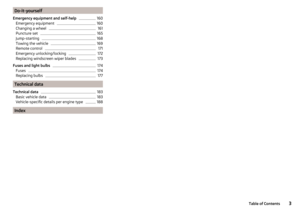 5
5 6
6 7
7 8
8 9
9 10
10 11
11 12
12 13
13 14
14 15
15 16
16 17
17 18
18 19
19 20
20 21
21 22
22 23
23 24
24 25
25 26
26 27
27 28
28 29
29 30
30 31
31 32
32 33
33 34
34 35
35 36
36 37
37 38
38 39
39 40
40 41
41 42
42 43
43 44
44 45
45 46
46 47
47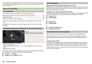 48
48 49
49 50
50 51
51 52
52 53
53 54
54 55
55 56
56 57
57 58
58 59
59 60
60 61
61 62
62 63
63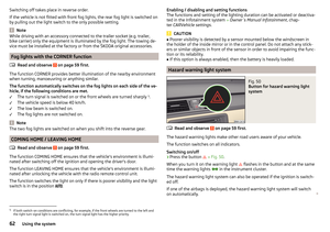 64
64 65
65 66
66 67
67 68
68 69
69 70
70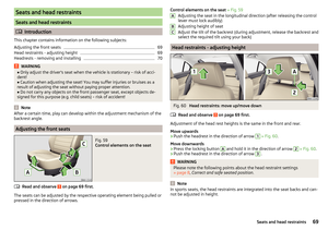 71
71 72
72 73
73 74
74 75
75 76
76 77
77 78
78 79
79 80
80 81
81 82
82 83
83 84
84 85
85 86
86 87
87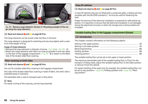 88
88 89
89 90
90 91
91 92
92 93
93 94
94 95
95 96
96 97
97 98
98 99
99 100
100 101
101 102
102 103
103 104
104 105
105 106
106 107
107 108
108 109
109 110
110 111
111 112
112 113
113 114
114 115
115 116
116 117
117 118
118 119
119 120
120 121
121 122
122 123
123 124
124 125
125 126
126 127
127 128
128 129
129 130
130 131
131 132
132 133
133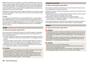 134
134 135
135 136
136 137
137 138
138 139
139 140
140 141
141 142
142 143
143 144
144 145
145 146
146 147
147 148
148 149
149 150
150 151
151 152
152 153
153 154
154 155
155 156
156 157
157 158
158 159
159 160
160 161
161 162
162 163
163 164
164 165
165 166
166 167
167 168
168 169
169 170
170 171
171 172
172 173
173 174
174 175
175 176
176 177
177 178
178 179
179 180
180 181
181 182
182 183
183 184
184 185
185 186
186 187
187 188
188 189
189 190
190 191
191 192
192 193
193 194
194 195
195 196
196 197
197 198
198 199
199 200
200 201
201 202
202 203
203 204
204 205
205 206
206 207
207