Page 113 of 208
Read and observe
on page 110 first.
EDL prevents the turning of the respective wheel of the driven axle. EDL
brakes the spinning wheel, if necessary, and transmits")
Electronic Differential Lock (EDL)Read and observe
on page 110 first.
EDL prevents the turning of the respective wheel of the driven axle. EDL
brakes the spinning wheel, if necessary, and transmits the driving force to the
other driving wheel. Driving becomes easier on road surfaces with different
traction under each wheel of the driven axle.
The EDL switches off automatically in order to avoid excessive heat generation
on the brake of the wheel being braked. Once the brakes have cooled down,
there is an automatic re-activation of EDL.
Brake Assist (HBA)
Read and observe
on page 110 first.
The HBA increases the braking effect and helps to reduce the braking dis-
tance.
The HBA is activated by the very quick operation of the brake pedal. In order to
achieve the shortest possible braking distance, the brake pedal must be ap-
plied firmly until the vehicle has come to a standstill.
The HBA function is automatically deactivated when the brake pedal is re-
leased.
Hill Start Assist (HHC)
Read and observe
on page 110 first.
When driving on slopes, HHC allows you to move your foot from the brake ped-al to the accelerator pedal without having to use the handbrake.
The system holds the brake pressure produced by the activation of the brake pedal for approx. 2 seconds after the brake pedal is released.
The HHC is active from a 5% slope if the driver's door is closed. HHC is only ev-
er active on slopes when in forward or reverse start off.
Multi collision brake (MCB)
Read and observe
on page 110 first.
The MCB helps to decrease speed after a collision through automatic brakinginterventions and to stabilize the vehicle. This reduces the risk of a subse-
quent crash due to uncontrolled vehicle movement.
The automatic brake interventions can take place only if the following condi-
tions are met.
There was a front, side and rear-end collision of a certain severity.
The impact speed was higher than approx. 10 km/h.
The brakes, the ESL and other required electrical systems remain function-
al after impact.
The accelerator pedal is not actuated.
Trailer stabilization system (TSA)
Read and observe
on page 110 first.
The TSA helps the combination stable in situations where the trailer sways
and then the whole trailer combination.
TSA brakes the individual wheels of the towing vehicle in order to damp the rocking motion of the entire vehicle combination.
The following conditions are required for the correct TSA function. The trailer was shipped from the factory or purchased from the ŠKODA
genuine accessories.
The trailer is electrically connected to the towing vehicle by means of the
trailer socket.
The TCS is activated.
The speed is higher than approx. 60 km/h.
Further information » page 121, Hitch and trailer .
111Assist systems
Page 114 of 208

Introduction
This chapter contains information on the following subjects:
Function
112
Display in the Infotainment display
113
Activation / deactivation
113
Automatic")
Parking assistance (ParkPilot)
Introduction
This chapter contains information on the following subjects:
Function
112
Display in the Infotainment display
113
Activation / deactivation
113
Automatic system activation when moving forward
114
Park Assist (hereinafter referred to as the system) draws attention via acoustic
signals or the Infotainment display when manoeuvring around obstacles in the
vicinity of the vehicle.
WARNING■ The general information relating to the use of assistance systems must
be observed » page 109, in section Introduction .■
Moving persons or objects may not be recognised by the system sensors.
■
Under certain circumstances, surfaces of certain objects and types of
clothing cannot reflect the system signals. For this reason, such people or
objects may not be recognised by the system sensors.
■
External noise sources may affect the signals of the system sensors. Un-
der adverse conditions, this may cause objects or people not to be recog-
nised by the system.
■
Before reversing, you should make sure that there are no small obstacles,
such as rocks, thin posts, trailer draw-bars etc. in front or behind your vehi-
cle. Such obstacles may not be recognised by the system sensors.
CAUTION
■ Keep the system sensors » Fig. 123 on page 112 clean, snow-and ice-free and
do not cover with any objects of any kind, otherwise the system functioning
may be impaired.■
Under adverse weather conditions (heavy rain, water vapour, very low or
high temperatures, etc.), the system function may be limited - “incorrect recog-
nition of obstacle”.
■
Accessories additionally installed on the vehicle rear, such as bicycle carriers,
can impair the system function.
FunctionFig. 123
Installation position of the sensors on the left side of the vehicle:
front/rear
Fig. 124
Sampled areas and range of the
sensors
Read and observe and on page 112 first.
The system uses ultrasound waves to calculate the distance between the
bumper and an obstacle. The ultrasonic sensors are, depending on vehicle
equipment,, located in the back or in the front bumper » Fig. 123.
Depending on the equipment, the following system versions can exist
» Fig. 124 .
▶ Version 1: warns of obstacles in the areas
C
,
D
.
▶ Version 2: warns of obstacles in the areas
A
,
B
,
C
,
D
.
112Driving
Page 115 of 208
Area » Fig. 124Version 1
(3 sensors)Version 2
(7 sensors)A-120B-60C160160D6060
Audible signals
The interval between the acoustic signals becomes shorter as the cle")
Approximate range of sensors (in cm)Area » Fig. 124Version 1
(3 sensors)Version 2
(7 sensors)A-120B-60C160160D6060
Audible signals
The interval between the acoustic signals becomes shorter as the clearance is
reduced. A continuous tone sounds from a distance of approx. 30 cm - danger
area. From this moment on do not continue driving!
The acoustic signals can be set in the Infotainment » Owner´s Manual Infotain-
ment , chapter CAR - Vehicle Settings .
Towing a trailer
When towing, or when another accessory is connected to the trailer socket on-
ly the areas
A
and
B
» Fig. 124 are active in the system.
Note
The signal tones for front obstacle recognition are factory-set to be higher
than for rear obstacle recognition.
Display in the Infotainment display
Fig. 125
Display
Read and observe and on page 112 first.
Function keys and obstacle warning » Fig. 125 Depending on the Infotainment type: Switching off park assistant dis-
play. Switching audible parking signals on/off.Message: Look! Safe to move?Colour of an object detected in the collision area (the distance to the
obstacle is less than 30 cm).
Stop driving in the direction of the ob-
stacle!Colour of an object detected in the manoeuvring area (the distance to
the obstacle is more than 30 cm).Colour of an object detected in the outside the manoeuvring area (the
distance to the obstacle is more than 30 cm).System failure (there is no indication of obstacles).
Activation / deactivation
Fig. 126
System key (option 2)
Read and observe and on page 112 first.
Activation
The activation of the system is initiated when the reverse gear is engaged, or
vehicles with the Variant 2, also by pressing the symbol key
» Fig. 126
.
This is confirmed by a short acoustic signal (the symbol in the button lights
up).
Deactivation
On vehicles with Version 1, the system can be deactivated by moving out of re-
verse gear.
For vehicles with Version 2, the system is deactivated by pressing the symbol
button or automatically at a speed over 10 km/h (the symbol
in the but-
ton goes out).
113Assist systems
Page 116 of 208

Displaying an error
If a warning signal sounds for about 3 seconds after activating the system and
there is no obstacle close to your car, this indicates a system fault. The fault is
also indicated by the symbol
flashing in the button. Seek help from a spe-
cialist garage.
Note
The system can only be activated with the symbol key at a speed of below
approx. 15 km / hr.
Automatic system activation when moving forward
Fig. 127
Infotainment display: Display
with automatic activation
Read and observe and on page 112 first.
The automatic system activation occurs when moving forward at a speed be- low 10 km / h when the vehicle approaches an obstacle.
After activation, the following is shown in the left pane of the Infotainment
display » Fig. 127 .
Acoustic signals are sounded as of a distance from the obstacle of around
50 cm.
The automatic display can be enabled or disabled in the Infotainment » Owner
´s Manual Infotainment , chapter CAR - vehicle settings .
Speed control system
Introduction
This chapter contains information on the following subjects:
Functioning
114
Operating Description
115The Cruise Control System (CCS) maintains a set speed without you having to
actuate the accelerator pedal.
The status where the CCS maintains the speed is referred to hereinafter as the
control .WARNING■
The general information relating to the use of assistance systems must
be observed » page 109, in section Introduction .■
After pressing the clutch pedal, no interrupted control occurs! For exam-
ple, if a different gear is engaged and the clutch pedal is released, control is
continued.
Functioning
Fig. 128
MAXI DOT display: Examples of status displays the CCS
114Driving
Page 117 of 208

Fig. 129
Segment display: Examples of status displays the CCS
Read and observe
on page 114 first.
CCS status displays » Fig. 128 , » Fig. 129
Speed set, but control is inactive.
Control is active.
No speed set.
System fault - seek assistance from a specialist garage immediately.
Basic requirements for starting the control The CCS is activated.
On vehicles with a manual transmission , the second gear or higher is en-
gaged.
On vehicles with an automatic transmission , the selector lever is in the
D/S position or in the Tiptronic position.
The current speed is higher than approx. 20 km/h.
This is only possible within the range which is permitted by the power output
and braking power of the engine.
WARNINGIf the engine power and engine braking effect is insufficient to maintain
the set speed, vehicle operation must be taken over!Operating DescriptionFig. 130
Cruise control system controls
Read and observe on page 114 first.
Overview of the CCS controls » Fig. 130ADeactivate CCS (delete set speed) Interrupt control (sprung position) Activate CCS (control deactivated)BTake control again a)
/ Increase speedCStart control / reduce speeda)
If no speed is set the current speed is adopted.
At the start of the regulation the CCS regulates the vehicle to the current
speed, and this speed is shown on the instrument cluster display. The warning
light illuminates in the instrument cluster.
Automatic control interruption
Automatic control interruption occurs if any of the following conditions are
met. ▶ The brake pedal is operated.
▶ When one of the brake assist systems (e.g. ESC) intervenes.
▶ Through an airbag deployment.
WARNING■Always deactivate the cruise control system after use to prevent the sys-
tem being switched on unintentionally.■
Control may only be resumed if the set speed is not too high for the cur-
rent traffic conditions.
115Assist systems
Page 118 of 208

NoteDuring control, speed can be increased by pressing the accelerator pedal. Re-
leasing the accelerator pedal will cause the speed to drop again to the set
speed.
Front Assist
Introduction
This chapter contains information on the following subjects:
Radar sensor
116
Operation
117
Distance warning (dangerous distance)
117
Warning and automatic braking
117
Disable/enable
118
Information messages
118
The Front Assist (hereinafter referred to as the system) warns you of the dan-
ger of a collision with a vehicle or another obstacle in front of the vehicle, and
tries to avoid a collision or mitigate its consequences by automatically applying
the brakes where necessary.
The area in front of the vehicle is monitored by a radar sensor » Fig. 131 on
page 116 .
WARNING■
The general information relating to the use of assistance systems must
be observed » page 109, in section Introduction .■
The system does not respond to crossing or oncoming objects.
CAUTION
In case of failure of more than one brake light on the vehicle or on the electri-
cally connected trailer, the system becomes unavailable.Radar sensorFig. 131
Mounting location of the radar
sensor
Read and observe and on page 116 first.
The radar sensor » Fig. 131(hereinafter referred to as the sensor) may detect
objects by emitting and receiving electromagnetic waves.
The sensor function may be impaired in the events of one of the following. ▶ The sensor is soiled by mud, snow and the like.
▶ The area in front and around the sensor is obscured by labels, auxiliary lights
and similar.
▶ When visibility is poor, (e.g. fog, heavy rain, thick snowfall).
If the sensor is dirty or covered, the corresponding message appears on the
display of the instrument cluster » page 118, Information messages .
WARNING■
If you suspect that the sensor is damaged, deactivate the system. Have
the sensor checked by a specialist garage.■
The sensor can become misaligned by collisions or by damage to the front
of the vehicle, the wheel arch or the underside of the vehicle. This can lead
to impaired function of the sensor - risk of accidents! Have the sensor
checked by a specialist garage.
■
The area in front and around the sensor should not be obscured by labels,
auxiliary lights and similar. This can lead to impaired function of the sensor
- risk of accidents!
CAUTION
Remove the snow with a brush and the ice with a solvent-free de-icer.116Driving
Page 119 of 208

OperationRead and observe
and on page 116 first.
The system support is provided in the following manner.▶ Alerts you about a dangerous proximity to the vehicle ahead.
▶ Warns you of an impending collision.
▶ Prepares the brakes for emergency braking prior to a detected danger.
▶ Assists with a brake action triggered by the driver.
▶ If the driver fails to respond to a detected danger, an automatic braking ac-
tion is performed.
The system can work only if the following basic conditions are met. The system is activated.
The TCS is activated » page 110, Traction control (TCS) .
The vehicle is moving forwards at a speed of more than approx. 5 km/h.
Note
The system can be impaired or may not be available, for example when driving
in “sharp ”curves or with an ESC engagement » page 110.
Distance warning (dangerous distance)
Fig. 132
Symbols in the instrument cluster: Note (dangerous
proximity)
Read and observe and on page 116 first.
The display of the distance warning is for vehicles with MAXI DOT display.
If a safe interval to the vehicle ahead falls below a minimum the display of the
instrument cluster shows the symbol
» Fig. 132 .
Immediately increase the proximity if the current traffic situation allows you to do so!
The proximity at which the warning is displayed depends on the current speed.
The warning may occur when driving between about 60 km/h and 210 km/h.
Warning and automatic braking
Fig. 133
Symbols in the instrument cluster: Warning or emer-
gency braking at low speed
Read and observe and on page 116 first.
Emergency braking at low speed
In a driving speed range of about 5 km/h to about 30 km/h the automatic brak-
ing action is not preceded by a warning. With an immediate impact hazard au-
tomatic braking is done with the breaking force increasing in stages.
With automatic braking the symbol appears » Fig. 133
in the display.
Advance warning
If the system detects a risk of collision, the symbol » Fig. 133
appears in the
display and you will hear an acoustic signal.
At the same time, the braking system is prepared for possible emergency brak- ing.
The pre-warning display can occur in the following situations.
▶ If there is a risk of collision with a moving obstacle in a driving speed range of
about 30 km/h to about 210 km/h.
▶ There is a risk of a collision with a stationary moving obstacle in a vehicle
speed range of approximately 30 km/h to about 85 km/h.
With a warning the brake pedal must be pressed or the moving obstacle is to
be avoided!
Acute alert
If the driver does not react to the advance warning, the system briefly applies
the brake automatically via an active brake intervention to draw attention to
the potential danger of a collision again.
117Assist systems
Page 120 of 208

Automatic Braking
If the driver fails to respond to the acute warning, the system starts to apply
the brakes automatically with increasing stopping power in several stages.
Brake assist
If the driver brakes inadequate with an impending collision, the system auto-
matically increases braking force.
The braking assistance only occurs as long as the brake pedal is being firmly
pressed down.
Note
■ If an automatic brake intervention is triggered by the system, the pressure in
the brake system increases and the brake pedal cannot be operated with the
normal pedal stroke.■
The automatic braking interventions can be cancelled by pressing the accel-
erator pedal or by steering intervention.
Disable/enable
Fig. 134
Buttons/dial: on the control lever/on the multifunction steering
wheel
Read and observe
and on page 116 first.
The system is automatically activated each time the ignition is switched on.
The system should only be disabled in exceptional cases »
.
On vehicles with the MAXI DOT display, the system can be activated / deactiva-
ted in the main menu in menu item
Assist systems
» page 42 .
Deactivation / activation in vehicles with segment displayButton
» Fig. 134ActionOperationAPress and hold at the top or downShow Front Assist menu itemBPress brieflyConfirm entry (disable / enable)
Deactivation / activation in vehicles with multi-function steering wheel
Button /dial
» Fig. 134ActionOperation
CPress brieflyShow Front Assist menu itemDPress brieflyConfirm entry (disable / enable)
Disable / enable and setting in the Infotainment
In the Infotainment the entire system or the functions warning and distance warning can be disabled / enabled » Owner´s Manual Infotainment , chap-
ter CAR - Vehicle Settings .
f the distance-warning function was deactivated before the ignition was
switched off, it remains deactivated after the ignition is switched on again.
WARNINGIn the following situations, Front Assist should be switched off for safety
reasons.■
When the vehicle is being towed away.
■
When the vehicle is on a rolling test bench.
■
If an unfounded warning or a system action was taken.
■
When on a truck, or a car ferry service or similar.
Information messages
Read and observe
and on page 116 first.
The warning symbols are shown in the instrument cluster display.
Front Assist: no sensor view.FRONT ASSIST NO SENSOR VIEW
The sensor is soiled or covered.
118Driving
 1
1 2
2 3
3 4
4 5
5 6
6 7
7 8
8 9
9 10
10 11
11 12
12 13
13 14
14 15
15 16
16 17
17 18
18 19
19 20
20 21
21 22
22 23
23 24
24 25
25 26
26 27
27 28
28 29
29 30
30 31
31 32
32 33
33 34
34 35
35 36
36 37
37 38
38 39
39 40
40 41
41 42
42 43
43 44
44 45
45 46
46 47
47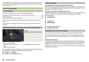 48
48 49
49 50
50 51
51 52
52 53
53 54
54 55
55 56
56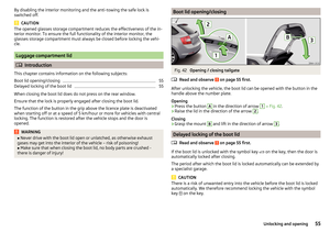 57
57 58
58 59
59 60
60 61
61 62
62 63
63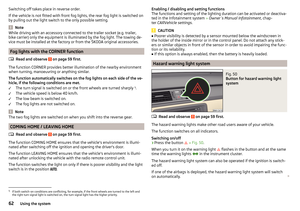 64
64 65
65 66
66 67
67 68
68 69
69 70
70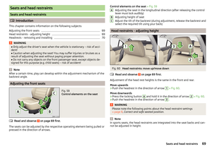 71
71 72
72 73
73 74
74 75
75 76
76 77
77 78
78 79
79 80
80 81
81 82
82 83
83 84
84 85
85 86
86 87
87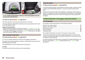 88
88 89
89 90
90 91
91 92
92 93
93 94
94 95
95 96
96 97
97 98
98 99
99 100
100 101
101 102
102 103
103 104
104 105
105 106
106 107
107 108
108 109
109 110
110 111
111 112
112 113
113 114
114 115
115 116
116 117
117 118
118 119
119 120
120 121
121 122
122 123
123 124
124 125
125 126
126 127
127 128
128 129
129 130
130 131
131 132
132 133
133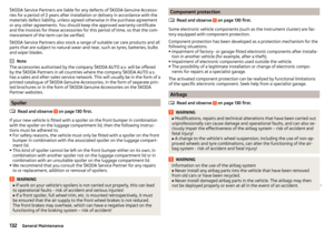 134
134 135
135 136
136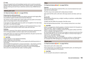 137
137 138
138 139
139 140
140 141
141 142
142 143
143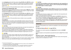 144
144 145
145 146
146 147
147 148
148 149
149 150
150 151
151 152
152 153
153 154
154 155
155 156
156 157
157 158
158 159
159 160
160 161
161 162
162 163
163 164
164 165
165 166
166 167
167 168
168 169
169 170
170 171
171 172
172 173
173 174
174 175
175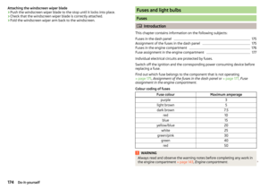 176
176 177
177 178
178 179
179 180
180 181
181 182
182 183
183 184
184 185
185 186
186 187
187 188
188 189
189 190
190 191
191 192
192 193
193 194
194 195
195 196
196 197
197 198
198 199
199 200
200 201
201 202
202 203
203 204
204 205
205 206
206 207
207