Page 89 of 248

Fuses and bulbs
– Remo
v
e the bolt ››› Fig. 95 1 from the fog
light gri
l
le with a screwdriver.
– Subsequently, remove the clips located on
the edge of the gri
lle with gentle leverage.
– Remove the bolts (3x) ›››
Fig. 96 2 to re-
mo v
e the f
og light.
– Remove the metal clip situated on the up-
per part
of the fog light by pulling towards
the exterior of the vehicle ››› Fig. 96 3 .
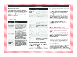
Removing the bulb holder Fig. 97
Front fog light. –
Remove connector ››
›
Fig. 97 1 from the
b u
l
b. –
Turn the bu
lb holder ››› Fig. 97 2 anti-
c loc
k
wise and pull.
– Remove the bulb by pressing on the bulb
holder and t
urning it counter-clockwise at
the same time.
– Installation involves all of the above steps
in rever
se sequence.
– Check that the bulb works properly. Changing the rear lights (on
the side panel)
R
emoving the rear light 1) Fig. 98
Remove the rear light unit from side
p anel
. Check which of the bulbs is defective.
– Open the luggage compartment to access
the r ainduct
ar
ea.
– Take the screwdriver or a Torx 20 key (T20)
from the v
ehicle tool kit and loosen (turn-
ing anti-clockwise) and remove the two re-
taining screws that secure the front of the
light ›››
Fig. 98 1 , taking care not to lose
them. »1)
In the case of LED rear lights of the side panel only
the turn s ign
al lamp can be changed. The illustra-
tions in the manual correspond to the bulb version
and do not correspond exactly to the LED version. 87
Technical data
Advice
Operation
Emergencies
Safety
Page 90 of 248

Emergencies
– Pu
l
l the rear light unit backward ( ››› Fig. 98
2 ) to remove the light from its housing.
Removing the bulb holder Fig. 99
Light connector at the rear of the rear
light u
nit
. Fig. 100
Retaining screws on reverse side of
r e
ar light
unit. –
Di s
c
onnect the light connector A ›››
Fig. 99 b y moving its side levers (arrows)
and p u
lling the connector outwards.
– Place the light on a level, horizontal surface
on top of a sof
t cloth so as not to scratch
the outer glass.
– Unscrew the four retaining screws from the
bul
b holder anti-clockwise using a screw-
driver or a Torx 20 key (T20) from the vehi-
cle tool kit ››› Fig. 100. Take care not to lose
the bulb holder retaining screws.
Changing bulbs Fig. 101
Position of the bulbs in the bulb
ho l
der The bulbs are secured with a bayonet fasten-
er
.
The t
able below gives an overview of the
bulb positions. –
Lightly pre
ss the defective bulb into the
bulb holder, then turn it anti-clockwise and
remove it.
– Fit the new bulb, pressing it into the bulb
holder and t
urn it clockwise as far as it will
go.
– Use a cloth to remove any fingerprints from
the glas
s part of the bulb.
– Check that the new bulb works properly.
– Replace the bulb holder.
– Screw in the bulb holder using the four
scr
ews, turning them clockwise.
Position of the bulbs
››› Fig. 101Bulb function
ATurn signals: PY21W NA LL
BSide lights-brake lights: P21/5W
CSide lights: P21/5W Note
Check the condition of the seal. If damaged, a
rep l
acement can be acquired from an Official
Service. 88
Page 91 of 248

Fuses and bulbs
Fitting the rear light Fig. 102
Fit the tail light unit. Fig. 103
Fit the tail light unit. –
Make sure the connector is correctly in
pl
ac
e. –
Pres
s the rear light unit backwards (driving
direction) by fitting the fastenings into the
rubber mountings ››› Fig. 102 A .
– Take the screwdriver or a Torx 20 key (T20)
from the
v
ehicle tool kit and tighten (turn-
ing clockwise ››› Fig. 103) the two retaining
screws that secure the front of the light.
Changing tail lights (on the
rear lid) R
emoving the bulb holder 1) Fig. 104
Remove the cover from the boot lid. Fig. 105
Remove the bulb holder. The rear lid must be open to change the
b
u
l
bs.
You can access the bulb holder for the inner
tail lights through the inside of the rear lid.
– Check which of the bulbs is defective. »1)
For rear-lid LED rear lights, only the reverse and
retr o f
og bulb can be replaced. The illustrations in
the manual correspond to the bulb version and do
not correspond exactly to the LED version. 89
Technical data
Advice
Operation
Emergencies
Safety
Page 92 of 248

Emergencies
– Open the c o
v
er to access the lights, turning
it by hand in the direction indicated by the
arrows.
– Access the lights by disconnecting the con-
nector 1
› ››
Fig. 105
and unscrewing
the bulb holder ››› Fig. 105 . Take care not
to lose the bulb holder retaining screw.
– Change the bulbs ›››
page 90.
Changing bulbs Fig. 106
Position of the bulbs in the bulb
ho l
der The bulbs are secured with a bayonet fasten-
er
.
The t
able below gives an overview of the
bulbs ››› table on page 90.
– Lightly press the defective bulb into the
bul
b holder, then turn it anti-clockwise and
remove it. –
Fit the new bu
lb, pressing it into the bulb
holder and turn it clockwise as far as it will
go.
– Use a cloth to remove any fingerprints from
the glas
s part of the bulb.
– Check that the new bulb works properly.
– Re-install the bulb holder ›››
page 90.
– Screw in the bulb holder.
Pos
ition of the bulbs
››› Fig. 106Bulb function
AReversing lights: P21W
BSide lights: R5W LL
CFog lights: P21W Note
One of the two sides may not be fitted with a
fog light, dependin g on the c
ountry and type
of driving. In this case, the hole for the light
is covered. Fitting the bulb-holder
–
Position the bulb holder on the tail light
and align it so th
at
it is securely seated.
– Screw in the bulb holder using the corre-
sponding s
crew. –
Make s
ure the connector is correctly in
place.
– Close the inner trim cover. Note
Check the condition of the seal. If damaged, a
rep l
acement can be acquired from an Official
Service. 90
Page 93 of 248
Fuses and bulbs
Changing the bulb on the num-
ber p l
at
e
Removing the bulb holder Fig. 107
Removing number plate light Fig. 108
Changing the bulb. –
Unscrew the screws to remove the bulb
› ›
›
Fig. 107. –
Remov
e the bulb, moving it in the direction
of the arrow and outwards ››› Fig. 108.
– Installation involves all of the above steps
in rever
se sequence. Note
Depending on how equipped the vehicle is,
the number pl at
e lights may be LEDs. LEDs
have an estimated life that exceeds than that
of the car. If a light with LEDs fails, go to an
authorised workshop for replacement. 91
Technical data
Advice
Operation
Emergencies
Safety
Page 94 of 248
Operation
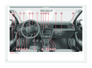
Fig. 109
Interior.92
Page 95 of 248

Controls and displays
Operation
C ontr
o
ls and displays
General instrument panel Electric window controls
. . . . . . . . . .120
Control for adjusting electric exteri-
or mirror s . . . . . . . . . . . . . . . . . . . . . . . . 130
Air outl
ets . . . . . . . . . . . . . . . . . . . . . . . . 147
Multifunction switch lever:
– Turn s ign
als, headlights, parking
lights, headlight flasher . . . . . . . .123
– Crui se c
ontrol system . . . . . . . . . . .176
Steering wheel:
– With horn
– With the driv
er front airbag . . . . . .13
– With c ontr
ols for audio, naviga-
tion system and telephone . . . . . .105
General instrument panel: instru-
ments and w arnin
g lamps . . . . . . . . 93
Multifunction switch lever:
– Multif
unction display . . . . . . . . . . .22
– Wind s
creen wipers and wind-
screen washers . . . . . . . . . . . . . . . . . 129
Air outlets . . . . . . . . . . . . . . . . . . . . . . . . 147
Depending on the equipment:
– Audio sy st
em
1 2
3
4
5
6
7
8
9 –
Nav ig
ation sy
stem
Hazard warning lights switch . . . . . .126
Control lamp for front passenger
airbag deactiv
ated warning lamp . .71
Front passenger airbag switch . . . .71
Depending on the equipment,
glove c
ompartment with: . . . . . . . . .135
– CD pla
yer* and/or SD card*
››› Booklet Radio
Front passenger airbag . . . . . . . . . . .13
Light switch . . . . . . . . . . . . . . . . . . . . . . 121
Headlight range control . . . . . . . . . . .122
Bonnet release lever . . . . . . . . . . . . . .205
Fuse compartment . . . . . . . . . . . . . . . . 81
Steering column adjustment lev-
er . . . . . . . . . . . . . . . . . . . . . . . . . . . . . . . . 13
Ignition lock . . . . . . . . . . . . . . . . . . . . . . 154
USB/AUX-IN input . . . . . . . . . . . . . . . . 109
Depending on the equipment: – Gear lev
er (manual gearbox) . . . .158
– Select or l
ever (automatic gear-
box) . . . . . . . . . . . . . . . . . . . . . . . . . . . . 160
Depending on the equipment:
– Drink ho l
der . . . . . . . . . . . . . . . . . . . . 136
– Ashtra y
holder . . . . . . . . . . . . . . . . . . 138
Rear shelf . . . . . . . . . . . . . . . . . . . . . . . . 135
Depending on the equipment, con-
tro l
s for:
10 11
12
13
14
15
16
17
18
19
20
21
22
23
24
25 –
Driv er he
at
ed seat . . . . . . . . . . . . . . 133
– Park a
ssist system . . . . . . . . . . . . . . 168
– Central
lock button . . . . . . . . . . . . . 114
– Heated r
ear window . . . . . . . . . . . . 128
– Start
-Stop system . . . . . . . . . . . . . . . 182
– Front p
assenger heated seat . . . .133
Depending on the equipment: – Heating c
ontrols . . . . . . . . . . . . . . . . 148
– Air conditioning c
ontrols . . . . . . . . 149
– Climatr
onic controls . . . . . . . . . . . . 151 Note
The location of the controls of right-hand
drive c ar
s differs slightly from the location
shown here ››› Fig. 109. However, the sym-
bols correspond to the respective controls. 26
93
Technical data
Advice
Operation
Emergencies
Safety
Page 96 of 248
Operation
Instruments and warning lamps
In s
trument
s
View of instrument panel Fig. 110
Instrument panel, on dash panel Details of the instruments
››
›
Fig. 110:
Rev counter (with the engine running, in
hundreds of revolutions per minute).
The beginning of the red zone of the rev
counter indicates the maximum speed in
any gear after running-in and with the en-
gine hot. However, it is advisable to
change up a gear or move the selector
lever to D (or lift your foot off the acceler-
1 ator) before the needle reaches the red
z
one
›
›
› .
En gine c
oo
lant temperature display
››› page 206.
Displays on the screen .
Adjuster button and display
››› page 97.
Speedometer.
2 3
4
5 Fuel gauge
› ››
p
ag e 98. WARNING
Any distraction may lead to an accident, with
the risk of
injury.
● Do not operate the instrument panel con-
trol
s when driving. 6
94