2015 MERCEDES-BENZ GLK-CLASS SUV tow
[x] Cancel search: towPage 316 of 386
Useful information
iThis Operator's Manual describes all
models and all standard and optional equip- ment of your vehicle available at the time of
publication of the Operator's Manual.
Country-specific differences are possible.
Please note that your vehicle may not be
equipped with all features described. This
also applies to safety-related systems and
functions.
iRead the information on qualified special-
ist workshops ( Y page 27).
Where will I find...?
Vehicle tool kit
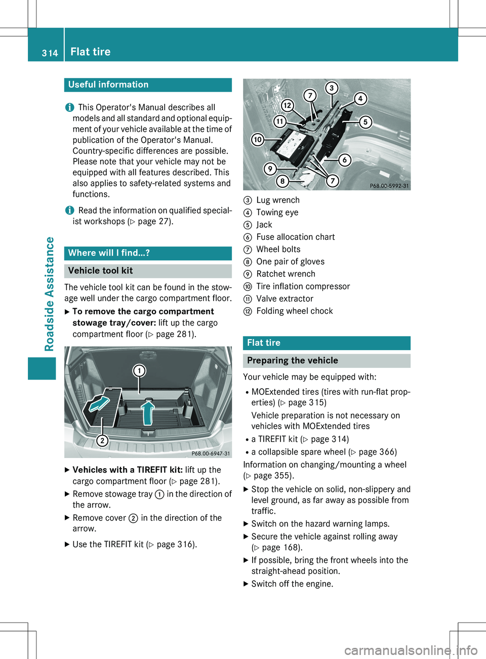
The vehicle tool kit can be found in the stow-
age well under the cargo compartment floor.
X To remove the cargo compartment
stowage tray/cover: lift up the cargo
compartment floor ( Y page 281).
X
Vehicles with a TIREFIT kit: lift up the
cargo compartment floor ( Y page 281).
X Remove stowage tray : in the direction of
the arrow.
X Remove cover ; in the direction of the
arrow.
X Use the TIREFIT kit ( Y page 316).
=Lug wrench
?Towing eye
AJack
BFuse allocation chart
CWheel bolts
DOne pair of gloves
ERatchet wrench
FTire inflation compressor
GValve extractor
HFolding wheel chock
Flat tire
Preparing the vehicle
Your vehicle may be equipped with:
R MOExtended tires (tires with run-flat prop-
erties) ( Y page 315)
Vehicle preparation is not necessary on
vehicles with MOExtended tires
R a TIREFIT kit ( Y page 314)
R a collapsible spare wheel ( Y page 366)
Information on changing/mounting a wheel
( Y page 355).
X Stop the vehicle on solid, non-slippery and
level ground, as far away as possible from
traffic.
X Switch on the hazard warning lamps.
X Secure the vehicle against rolling away
(Y page 168).
X If possible, bring the front wheels into the
straight-ahead position.
X Switch off the engine.
314Flat tire
Roadside Assistance
Page 319 of 386
Using the TIREFIT kit
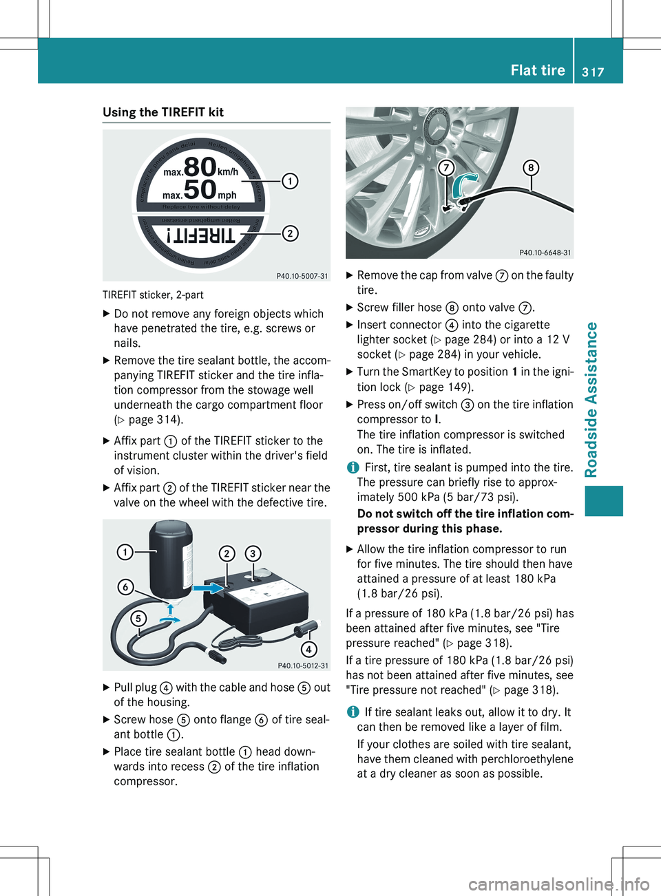
TIREFIT sticker, 2-part
XDo not remove any foreign objects which
have penetrated the tire, e.g. screws or
nails.
X Remove the tire sealant bottle, the accom-
panying TIREFIT sticker and the tire infla-
tion compressor from the stowage well
underneath the cargo compartment floor
( Y page 314).
X Affix part : of the TIREFIT sticker to the
instrument cluster within the driver's field
of vision.
X Affix part ; of the TIREFIT sticker near the
valve on the wheel with the defective tire.
X Pull plug ? with the cable and hose A out
of the housing.
X Screw hose A onto flange B of tire seal-
ant bottle :.
X Place tire sealant bottle : head down-
wards into recess ; of the tire inflation
compressor.
X Remove the cap from valve C on the faulty
tire.
X Screw filler hose D onto valve C.
X Insert connector ? into the cigarette
lighter socket ( Y page 284) or into a 12 V
socket ( Y page 284) in your vehicle.
X Turn the SmartKey to position 1 in the igni-
tion lock ( Y page 149).
X Press on/off switch = on the tire inflation
compressor to I.
The tire inflation compressor is switched
on. The tire is inflated.
iFirst, tire sealant is pumped into the tire.
The pressure can briefly rise to approx-
imately 500 kPa (5 bar/73 psi).
Do not switch off the tire inflation com-
pressor during this phase.
X Allow the tire inflation compressor to run
for five minutes. The tire should then have
attained a pressure of at least 180 kPa
(1.8 bar/26 psi).
If a pressure of 180 kPa (1.8 bar/26 psi) has been attained after five minutes, see "Tire
pressure reached" ( Y page 318).
If a tire pressure of 180 kPa (1.8 bar/26 psi) has not been attained after five minutes, see"Tire pressure not reached" ( Y page 318).
iIf tire sealant leaks out, allow it to dry. It
can then be removed like a layer of film.
If your clothes are soiled with tire sealant,
have them cleaned with perchloroethylene
at a dry cleaner as soon as possible.
Flat tire317
Roadside Assistance
Z
Page 320 of 386
Tire pressure not reached
If a pressure of 180 kPa (1.8 bar/26 psi) has
not been attained after five minutes:
X Switch off the tire inflation compressor.
X Unscrew the filler hose from the valve of
the faulty tire.
X Very slowly drive forwards or back up
approximately 30 ft (10 m).
X Pump up the tire again.
After a maximum of five minutes the tire
pressure must be at least 180 kPa (1.8 bar/
26 psi).
GWARNING
If the required tire pressure is not reached
after the specified time, the tire is too badly
damaged. The tire sealant cannot repair the
tire in this instance. Damaged tires and a tirepressure that is too low can significantly
impair the vehicle's braking and driving char-
acteristics. There is a risk of accident.
Do not continue driving. Contact a qualified
specialist workshop.
Tire pressure reached
If a tire pressure of 180 kPa (1.8 bar/26 psi) has been attained after five minutes:
X Switch off the tire inflation compressor.
X Unscrew the filler hose from the valve of
the faulty tire.
! After use, excess tire sealant may run out
of the filler hose. This could cause stains.
Therefore, place the filler hose in the plastic
bag that contained the TIREFIT kit.
X Stow the tire sealant bottle and the tire
inflation compressor.
X Pull away immediately .
GWARNING
A tire temporarily sealed with tire sealant
impairs the driving characteristics and is not
suitable for higher speeds. There is a risk of
accident.
You should therefore adapt your driving style
accordingly and drive carefully. Do not exceed
the specified maximum speed with a tire that
has been repaired using tire sealant.
The maximum speed for a tire sealed with tire
sealant is 50 mph (80 km/h). The upper part of the TIREFIT sticker must be affixed to the
instrument cluster in the driver's field of
vision. X Stop after driving for approximately ten
minutes and check the tire pressure with
the tire inflation compressor.
The tire pressure must now be at least
130 kPa (1.3 bar/19 psi).
GWARNING
If the required tire pressure is not reached
after driving for a short period, the tire is too
badly damaged. The tire sealant cannot repair
the tire in this instance. Damaged tires and a
tire pressure that is too low can significantly
impair the vehicle's braking and driving char-
acteristics. There is a risk of accident.
Do not continue driving. Contact a qualified
specialist workshop.
iIn cases such as the one mentioned
above, contact an authorized Mercedes-
Benz Center. Or call 1-800-FOR-MERCedes
(in the USA) or 1-800-387-0100 (in Can-
ada).
X Correct the tire pressure if it is still at least
130 kPa (1.3 bar/19 psi). See the Tire and
Loading Information placard on the driver's side B-pillar or the tire pressure table in the fuel filler flap for values.
X To increase the tire pressure: switch on
the tire inflation compressor.
318Flat tire
Roadside Assistance
Page 327 of 386
XFirst, remove the jumper cables from ground point A and negative terminal ?, then from
positive clamp ; and positive terminal =. Begin each time at the contacts on your own
vehicle first.
X Close cover : of positive terminal ; after removing the jumper cables.
X Have the battery checked at a qualified specialist workshop.
iJump-starting is not considered to be a normal operating condit ion.
iJumper cables and further information regarding jump-starting can be obtained at any
qualified specialist workshop.
Towing and tow-starting
Important safety notes
GWARNING
You can no longer steer the vehicle if the
steering wheel lock has been engaged. There is a risk of an accident.
Always switch off the ignition when towing the
vehicle with a tow cable or a tow bar.
GWARNING
When towing or tow-starting another vehicle
and its weight is greater than the permissible gross weight of your vehicle, the:
R the towing eye could detach itself
R the vehicle/trailer combination could roll-
over.
There is a risk of an accident.
When towing or tow-starting another vehicle,
its weight should not be greater than the per- missible gross weight of your vehicle.
Details on the permissible gross vehicle
weight of your vehicle can be found on the
vehicle identification plate ( Y page 372).
! If DISTRONIC PLUS or the HOLD function
is activated, the vehicle brakes automati-
cally in certain situations. To prevent damage to the vehicle, deacti-
vate DISTRONIC PLUS and the HOLD func-
tion in the following or other similar situa-
tions:
R when towing the vehicle
R in the car wash
! The vehicle can be towed a maximum of
30 miles (50km). The towing speed of
30 mph (50 km/h) must not be exceeded.
If the vehicle has to be towed more than
30 miles (50km), the entire vehicle must be
raised and transported.
! Only secure the tow rope or tow bar at the
towing eyes. Otherwise, the vehicle could
be damaged.
! Do not use the towing eyes for recovery
purposes as this could damage the vehicle.
If in doubt, recover the vehicle with a crane.
! When towing, pull away slowly and
smoothly. If the tractive power is too high,
the vehicles could be damaged.
! Do not tow with sling-type equipment.
This could damage the vehicle.
! On vehicles with KEYLESS-GO, use the
SmartKey instead of the Start/Stop but-
ton. Turn the SmartKey to position 2 in the
ignition lock and shift the automatic trans- mission to N. Then, turn the SmartKey back
to 0 and leave it in the ignition lock.
It is better to have the vehicle transported
than to have it towed away.
Towing and tow-starting325
Roadside Assistance
Z
Page 328 of 386
The automatic transmission must be in posi-
tion N when the vehicle is being towed.
The battery must be connected and charged.
Otherwise, you:
R cannot turn the SmartKey to position 2 in
the ignition lock
R cannot shift the automatic transmission to
position N
iDisarm the automatic locking feature
before the vehicle is towed ( Y page 86). You
could otherwise be locked out when push-
ing or towing the vehicle.
Installing/removing the towing eye
Installing the towing eye
GWARNING
The exhaust tail pipe may be very hot. There is
a risk of burns when removing the rear cover.
Do not touch the exhaust pipe. Take particular
care when removing the rear cover.
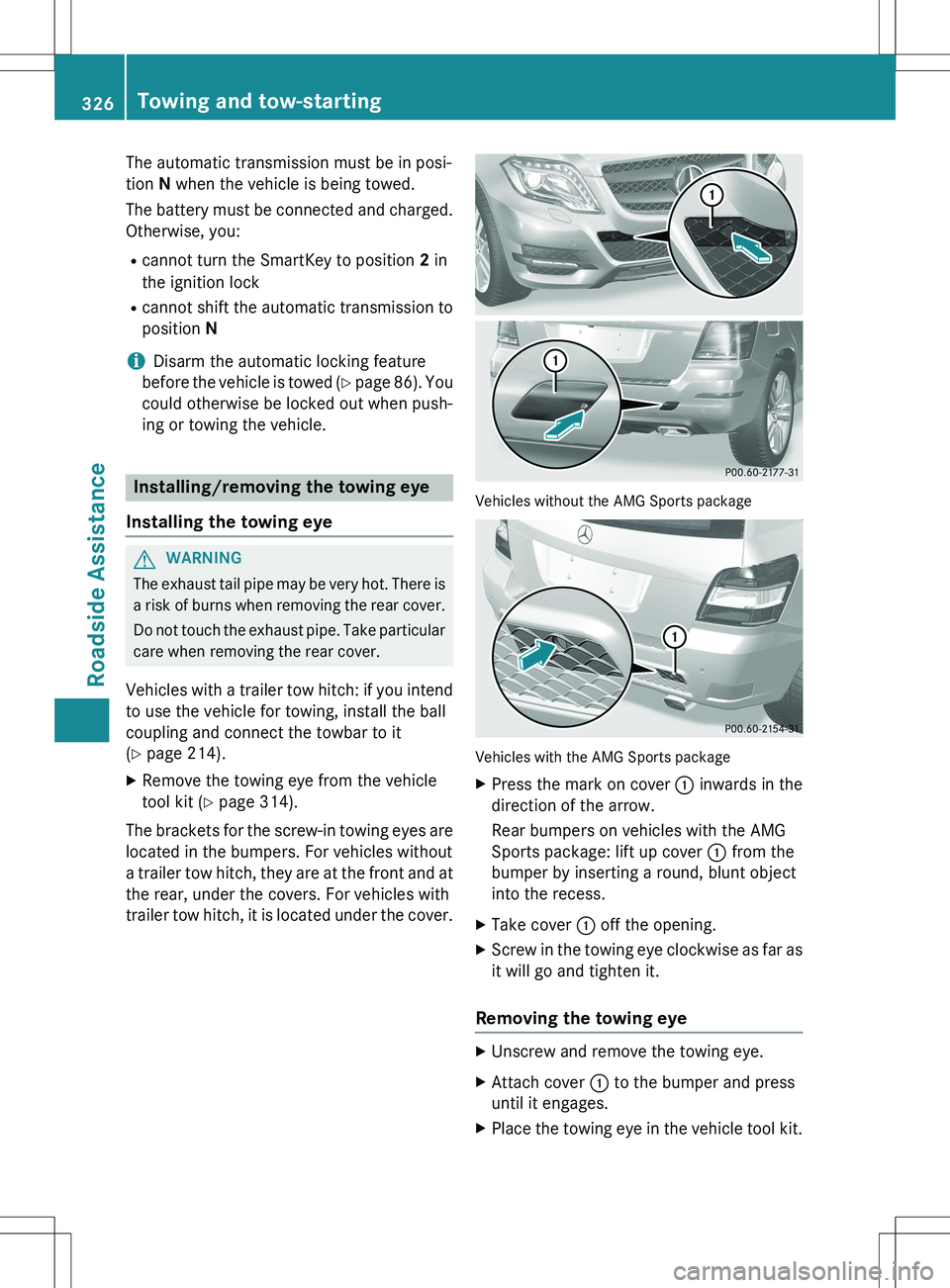
Vehicles with a trailer tow hitch: if you intend to use the vehicle for towing, install the ball
coupling and connect the towbar to it
( Y page 214).
X Remove the towing eye from the vehicle
tool kit ( Y page 314).
The brackets for the screw-in towing eyes are
located in the bumpers. For vehicles without
a trailer tow hitch, they are at the front and at
the rear, under the covers. For vehicles with
trailer tow hitch, it is located under the cover.
Vehicles without the AMG Sports package
Vehicles with the AMG Sports package
X Press the mark on cover : inwards in the
direction of the arrow.
Rear bumpers on vehicles with the AMG
Sports package: lift up cover : from the
bumper by inserting a round, blunt object
into the recess.
X Take cover : off the opening.
X Screw in the towing eye clockwise as far as
it will go and tighten it.
Removing the towing eye
XUnscrew and remove the towing eye.
X Attach cover : to the bumper and press
until it engages.
X Place the towing eye in the vehicle tool kit.
326Towing and tow-starting
Roadside Assistance
Page 329 of 386
Towing a vehicle with both axles on
the ground
It is important that you observe the safety
instructions when towing away your vehicle
(Y page 325).
X Switch on the hazard warning lamps
(Y page 119).
iWhen towing with the hazard warning
lamps switched on, use the combination
switch as usual to signal a change of direc- tion. In this case, only the indicator lamps
for the direction of travel flash. After reset- ting the combination switch, the hazard
warning lamp starts flashing again.
X Turn the SmartKey to position 2 in the igni-
tion lock.
X When the vehicle is stationary, depress the
brake pedal and keep it depressed.
X Shift the automatic transmission to posi-
tion N.
X Release the brake pedal.
X Release the parking brake.
Towing the vehicle with the rear axle
raised
Only possible for vehicles without
4MATIC.
When towing your vehicle with the rear axle
raised, it is important that you observe the
safety instructions ( Y page 325).
! The ignition must be switched off if you
are towing the vehicle with the rear axle
raised. Intervention by ESP ®
could other-
wise damage the brake system.
X Bring the front wheels into the straight-
ahead position.
X Switch on the hazard warning lamps
(Y page 119). X
Turn the SmartKey to position 0 in the igni-
tion lock and remove the SmartKey from
the ignition lock.
X When leaving the vehicle, take the Smart-
Key or the KEYLESS-GO key with you.
Transporting the vehicle
The towing eyes or trailer tow hitch can be
used to pull the vehicle onto a trailer or trans-
porter if you wish to transport it.
X Turn the SmartKey to position 2 in the igni-
tion lock.
X Shift the automatic transmission to posi-
tion N.
As soon as the vehicle has been loaded:
X Prevent the vehicle from rolling away by
applying the parking brake.
X Shift the automatic transmission to posi-
tion P.
X Turn the SmartKey to position 0 in the igni-
tion lock and remove the SmartKey from
the ignition lock.
X Secure the vehicle.
! You may only secure the vehicle by the
wheels, not by parts of the vehicle such as
axle or steering components. Otherwise,
the vehicle could be damaged.
Notes on 4MATIC vehicles
!
Vehicles with 4MATIC must not be towed
with either the front or the rear axle raised, as doing so will damage the transmission.
If the vehicle has transmission damage or
damage to the front or rear axle, have it trans-
ported on a transporter or trailer.
In the event of damage to the electrical
system
If the battery is defective, the automatic
transmission will be locked in position P. To
shift the automatic transmission to position
N , you must provide power to the vehicle's
Towing and tow-starting327
Roadside Assistance
Z
Page 330 of 386
electrical system in the same way as when
jump-starting (Y page 323).
Have the vehicle transported on a transporter or trailer.
Tow-starting (emergency engine
starting)
!
Vehicles with automatic transmission
must not be started by tow-starting. This
could otherwise damage the transmission.
You can find information on "Jump-starting" at
( Y page 323).
Fuses
Important safety notes
GWARNING
If you manipulate or bridge a faulty fuse or if
you replace it with a fuse with a higher amper-
age, the electric cables could be overloaded.
This could result in a fire. There is a risk of an
accident and injury.
Always replace faulty fuses with the specified
new fuses having the correct amperage.
! Only use fuses that have been approved
for Mercedes-Benz vehicles and which
have the correct fuse rating for the system concerned. Otherwise, components or sys-
tems could be damaged.
The fuses in your vehicle serve to close down faulty circuits. If a fuse blows, all the compo- nents on the circuit and their functions stop
operating.
Blown fuses must be replaced with fuses of
the same rating, which you can recognize by
the color and value. The fuse ratings are listedin the fuse allocation chart.
If a newly inserted fuse also blows, have the
cause traced and rectified at a qualified spe-
cialist workshop, e.g. an authorized
Mercedes-Benz Center.
Before changing a fuse
X Secure the vehicle against rolling away
(Y page 168).
X Switch off all electrical consumers.
X Turn the SmartKey to position 0 in the igni-
tion lock and remove it ( Y page 149).
or
X On vehicles with KEYLESS-GO, make sure
the ignition is switched off ( Y page 149).
All indicator lamps in the instrument cluster
must be off.
The fuses are located in various fuse boxes:
R Fuse box on the driver's side of the dash-
board
R Fuse box in the engine compartment on the
left-hand side of the vehicle, when viewed
in the direction of travel
R Fuse box in the stowage well under the
cargo compartment floor on the right-hand
side of the vehicle, when viewed in the
direction of travel
The fuse allocation chart is in the vehicle tool kit which is located in the stowage compart-
ment under the cargo compartment floor
( Y page 314).
Dashboard fuse box
!
Do not use a pointed object such as a
screwdriver to open the cover in the dash-
board. You could damage the dashboard or
the cover.
! Make sure that no moisture can enter the
fuse box when the cover is open.
! When closing the cover, make sure that it
is lying correctly on the fuse box. Moisture seeping in or dirt could otherwise impair
the operation of the fuses.
328Fuses
Roadside Assistance
Page 332 of 386
XTo open: lift up cargo compartment
floor ;(Y page 281).
X Remove stowage compartment :.
X Open cover = of fuse box downwards.
330Fuses
Roadside Assistance