2015 MERCEDES-BENZ GLE SUV tow
[x] Cancel search: towPage 278 of 453
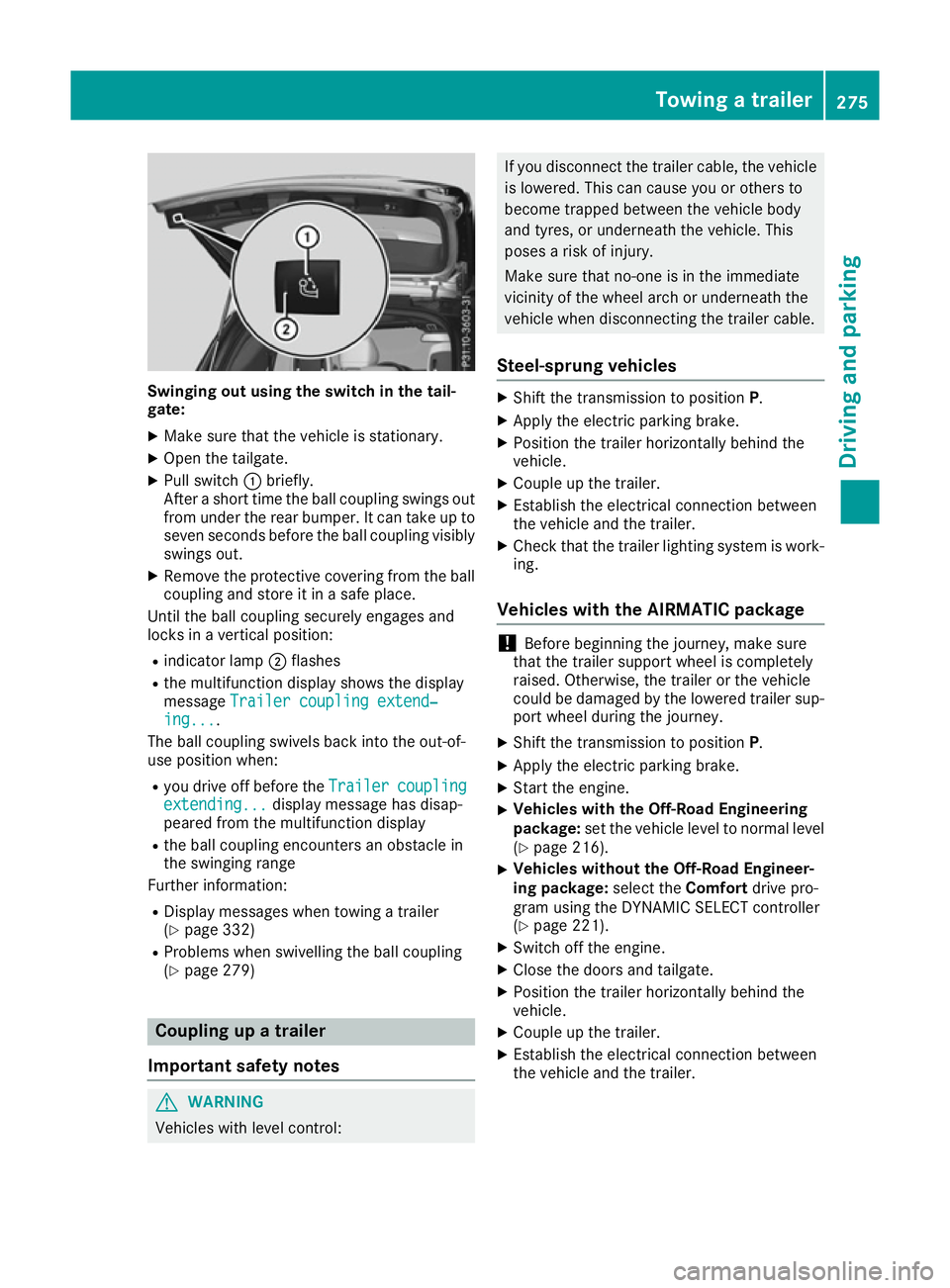
Swinging out using the switch in the tail-
gate:
X Make sure that the vehicle is stationary.
X Open the tailgate.
X Pull switch :briefly.
After a short time the ball coupling swings out from under the rear bumper. It can take up to
seven seconds before the ball coupling visibly
swings out.
X Remove the protective covering from the ball
coupling and store it in a safe place.
Until the ball coupling securely engages and
locks in a vertical position:
R indicator lamp ;flashes
R the multifunction display shows the display
message Trailer coupling extend‐ Trailer coupling extend‐
ing...
ing....
The ball coupling swivels back into the out-of-
use position when:
R you drive off before the Trailer Trailercoupling
coupling
extending...
extending... display message has disap-
peared from the multifunction display
R the ball coupling encounters an obstacle in
the swinging range
Further information:
R Display messages when towing a trailer
(Y page 332)
R Problems when swivelling the ball coupling
(Y page 279) Coupling up a trailer
Important safety notes G
WARNING
Vehicles with level control: If you disconnect the trailer cable, the vehicle
is lowered. This can cause you or others to
become trapped between the vehicle body
and tyres, or underneath the vehicle. This
poses a risk of injury.
Make sure that no-one is in the immediate
vicinity of the wheel arch or underneath the
vehicle when disconnecting the trailer cable.
Steel-sprung vehicles X
Shift the transmission to position P.
X Apply the electric parking brake.
X Position the trailer horizontally behind the
vehicle.
X Couple up the trailer.
X Establish the electrical connection between
the vehicle and the trailer.
X Check that the trailer lighting system is work-
ing.
Vehicles with the AIRMATIC package !
Before beginning the journey, make sure
that the trailer support wheel is completely
raised. Otherwise, the trailer or the vehicle
could be damaged by the lowered trailer sup- port wheel during the journey.
X Shift the transmission to position P.
X Apply the electric parking brake.
X Start the engine.
X Vehicles with the Off-Road Engineering
package:
set the vehicle level to normal level
(Y page 216).
X Vehicles without the Off-Road Engineer-
ing package:
select theComfortdrive pro-
gram using the DYNAMIC SELECT controller
(Y page 221).
X Switch off the engine.
X Close the doors and tailgate.
X Position the trailer horizontally behind the
vehicle.
X Couple up the trailer.
X Establish the electrical connection between
the vehicle and the trailer. Towing a trailer
275Driving and parking Z
Page 279 of 453
X
Check that the trailer lighting system is work-
ing.
X Push the combination switch upwards and
downwards and check whether the corre-
sponding turn signal on the trailer is flashing.
A connected trailer is only detected when the
electrical connection is established correctly
and when the lighting system is working prop-
erly. The function of other systems also depends on this, for example:
R ESP ®
R PARKTRONIC
R Active Parking Assist
R Active Blind Spot Assist
R Active Lane Keeping Assist
i Vehicles with the AIRMATIC package:
if
you couple up a trailer, the vehicle initially
remains at the selected level of the drive pro- gram set. Observe the following when cou-
pling up a trailer:
R If the normal level was not selected previ-
ously, the vehicle automatically adopts the
normal level starting from a speed of
30 km/h. Even at higher speeds, it does not drop below the normal level.
R Vehicle levels below the normal level are
not available.
R The raised level is available up to a speed of
30 km/h.
R This also applies when using accessories
that are plugged into the socket of the
trailer tow hitch (e.g. a bicycle rack).
R Before driving with a trailer, please observe
the information on the trailer support
wheel. Uncoupling a trailer
Important safety notes G
WARNING
If you uncouple a trailer with an engaged over- run brake, you could trap your hand between
the vehicle and the trailer drawbar. This poses a risk of injury.
Do not uncouple a trailer with an engaged
overrun brake. G
WARNING
Vehicles with level control:
If you disconnect the trailer cable, the vehicle is lowered. This can cause you or others to
become trapped between the vehicle body
and tyres, or underneath the vehicle. This
poses a risk of injury.
Make sure that no-one is in the immediate
vicinity of the wheel arch or underneath the
vehicle when disconnecting the trailer cable.
! Do not disconnect a trailer with an engaged
overrun brake. Otherwise, your vehicle could
be damaged by the rebounding of the overrun
brake.
! Remove the adapter cable before folding in
the ball coupling. You could otherwise dam-
age the rear bumper and the adapter cable.
Steel-sprung vehicles X
Shift the transmission to position P.
X Apply the electric parking brake.
X Secure the trailer against rolling away.
X Remove the trailer cable and decouple the
trailer.
Vehicles with the AIRMATIC package X
Shift the transmission to position P.
X Apply the electric parking brake.
X Start the engine.
X Close the doors and tailgate.
X Secure the trailer against rolling away.
X Remove the trailer cable and decouple the
trailer.
X Switch off the engine. Swinging the ball coupling in
! Do not attempt to speed the up the swing-
out procedure by applying additional pressure
with your foot. The system could otherwise be
mechanically damaged. 276
Towing a trailerDriving and parking
Page 280 of 453
Fold the ball coupling back in if you are not using
the trailer tow hitch. To fold the ball coupling in,
you have two options:
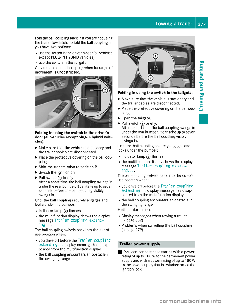
R use the switch in the driver's door (all vehicles
except PLUG-IN HYBRID vehicles)
R use the switch in the tailgate
Only release the ball coupling when its range of
movement is unobstructed. Folding in using the switch in the driver's
door (all vehicles except plug-in hybrid vehi-
cles):
X Make sure that the vehicle is stationary and
the trailer cables are disconnected.
X Place the protective covering on the ball cou-
pling.
X Shift the transmission to position P.
X Switch the ignition on.
X Pull switch :briefly.
After a short time the ball coupling swings in
under the rear bumper. It can take up to seven seconds before the ball coupling visibly
swings in.
Until the ball coupling securely engages and
locks under the bumper:
R indicator lamp ;flashes
R the multifunction display shows the display
message Trailer coupling extend‐
Trailer coupling extend‐
ing... ing....
The ball coupling swivels back into the out-of-
use position when:
R you drive off before the Trailer
Trailer coupling
coupling
extending... extending... display message has disap-
peared from the multifunction display
R the ball coupling encounters an obstacle in
the swinging range Folding in using the switch in the tailgate:
X Make sure that the vehicle is stationary and
the trailer cables are disconnected.
X Place the protective covering on the ball cou-
pling.
X Open the tailgate.
X Pull switch :briefly.
After a short time the ball coupling swings in
under the rear bumper. It can take up to seven seconds before the ball coupling visibly
swings in.
Until the ball coupling securely engages and
locks under the bumper:
R indicator lamp ;flashes
R the multifunction display shows the display
message Trailer coupling extend‐
Trailer coupling extend‐
ing... ing....
The ball coupling swivels back into the out-of-
use position when:
R you drive off before the Trailer
Trailercoupling
coupling
extending...
extending... display message has disap-
peared from the multifunction display
R the ball coupling encounters an obstacle in
the swinging range
Further information:
R Display messages when towing a trailer
(Y page 332)
R Problems when swivelling the ball coupling
(Y page 279) Trailer power supply
! You can connect accessories with a power
rating of up to 180 W to the permanent power supply and with a power rating of up to 180 Wto the power supply that is switched on via the
ignition lock. Towing a trailer
277Driving and parking Z
Page 281 of 453
The trailer battery may not be charged from
the power supply.
When it leaves the factory, your vehicle's trailer
socket is equipped with a permanent power
supply and a power supply that is switched on
via the ignition lock.
The permanent power supply is supplied via
trailer socket pin 9.
The power supply that is switched on via the
ignition lock is supplied via trailer socket pin 10.
The trailer's permanent power supply is
switched off in the event of low vehicle supply
voltage and after six hours at the latest.
You can find more information about fitting the
trailer electrics at a qualified specialist work-
shop.
X To switch the connected power supply on
or off: turn the key to position 2or 0respec-
tively (Y page 158). Failure check for LEDs
If LED lamps are fitted in the trailer, a malfunc-
tion message may appear in the multifunction
display even if there is no fault. The reason for
the error message may be that the current has
fallen below the minimum of 50 mA.
To ensure reliable indication of the failure, each LED chain in the trailer lighting must be guaran-
teed a minimum current of 50 mA. Trailer with 7-pin connector
General notes Trailer with 7-pin connector:
you can connect
to the 13-pin socket on the ball coupling using
an adapter or, if necessary, an adapter cable.
Both can be obtained at a qualified specialist
workshop.
Fitting the adapter !
Make sure that there is sufficient cable play
so that the cable cannot become detached
when cornering.
! Remove the adapter cable before folding in
the ball coupling. You could otherwise dam-
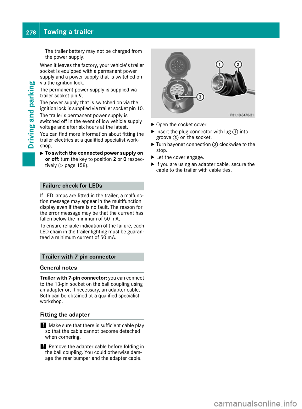
age the rear bumper and the adapter cable. X
Open the socket cover.
X Insert the plug connector with lug :into
groove =on the socket.
X Turn bayonet connection ;clockwise to the
stop.
X Let the cover engage.
X If you are using an adapter cable, secure the
cable to the trailer with cable ties. 278
Towing a trailerDriving and parking
Page 282 of 453
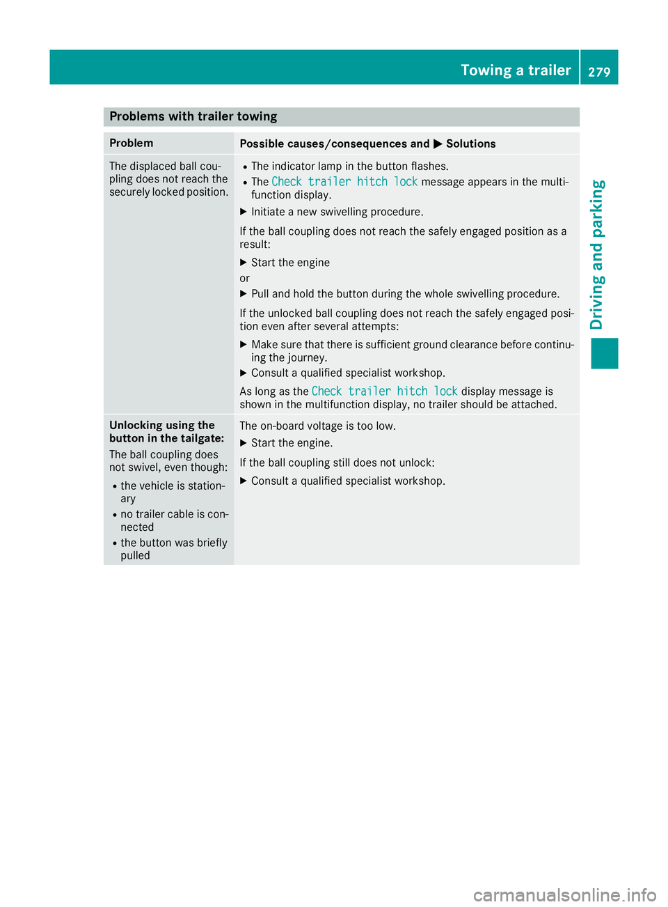
Problems with trailer towing
Problem
Possible causes/consequences and
M
MSolutions The displaced ball cou-
pling does not reach the
securely locked position. R
The indicator lamp in the button flashes.
R The Check trailer hitch lock Check trailer hitch lock message appears in the multi-
function display.
X Initiate a new swivelling procedure.
If the ball coupling does not reach the safely engaged position as a
result:
X Start the engine
or
X Pull and hold the button during the whole swivelling procedure.
If the unlocked ball coupling does not reach the safely engaged posi- tion even after several attempts:
X Make sure that there is sufficient ground clearance before continu-
ing the journey.
X Consult a qualified specialist workshop.
As long as the Check trailer hitch lock
Check trailer hitch lock display message is
shown in the multifunction display, no trailer should be attached. Unlocking using the
button in the tailgate:
The ball coupling does
not swivel, even though:
R
the vehicle is station-
ary
R no trailer cable is con-
nected
R the button was briefly
pulled The on-board voltage is too low.
X Start the engine.
If the ball coupling still does not unlock:
X Consult a qualified specialist workshop. Towing a trailer
279Driving and parking Z
Page 283 of 453
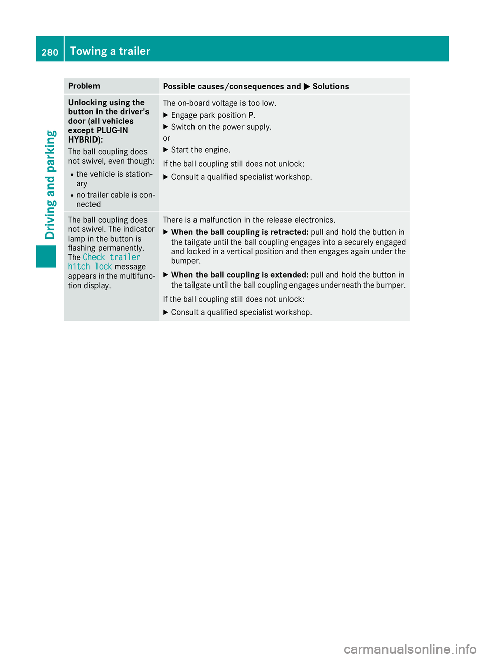
Problem
Possible causes/consequences and
M
MSolutions Unlocking using the
button in the driver's
door (all vehicles
except PLUG-IN
HYBRID):
The ball coupling does
not swivel, even though:
R the vehicle is station-
ary
R no trailer cable is con-
nected The on-board voltage is too low.
X Engage park position P.
X Switch on the power supply.
or X Start the engine.
If the ball coupling still does not unlock: X Consult a qualified specialist workshop. The ball coupling does
not swivel. The indicator
lamp in the button is
flashing permanently.
The
Check trailer Check trailer
hitch lock
hitch lock message
appears in the multifunc- tion display. There is a malfunction in the release electronics.
X When the ball coupling is retracted: pull and hold the button in
the tailgate until the ball coupling engages into a securely engaged
and locked in a vertical position and then engages again under the
bumper.
X When the ball coupling is extended: pull and hold the button in
the tailgate until the ball coupling engages underneath the bumper.
If the ball coupling still does not unlock:
X Consult a qualified specialist workshop. 280
Towing a trailerDriving and parking
Page 289 of 453
If you reset the values in the "ECO display", the
values in the "From start" trip computer are also
reset. If you reset the values in the "From start"
trip computer, the values in the "ECO display"
are also reset. Navigation menu
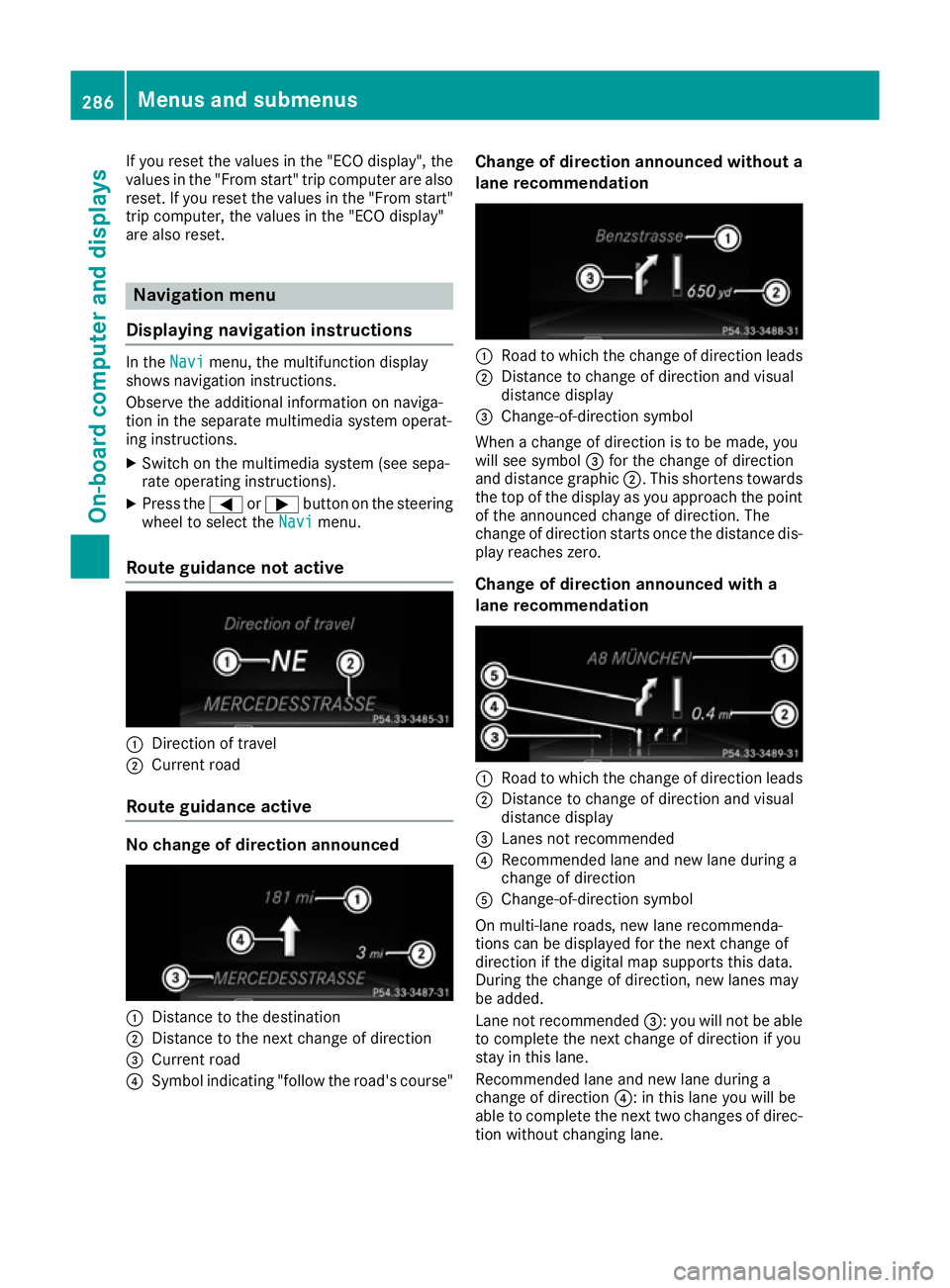
Displaying navigation instructions In the
Navi Navimenu, the multifunction display
shows navigation instructions.
Observe the additional information on naviga-
tion in the separate multimedia system operat-
ing instructions.
X Switch on the multimedia system (see sepa-
rate operating instructions).
X Press the =or; button on the steering
wheel to select the Navi
Navi menu.
Route guidance not active :
Direction of travel
; Current road
Route guidance active No change of direction announced
:
Distance to the destination
; Distance to the next change of direction
= Current road
? Symbol indicating "follow the road's course" Change of direction announced without a
lane recommendation :
Road to which the change of direction leads
; Distance to change of direction and visual
distance display
= Change-of-direction symbol
When a change of direction is to be made, you
will see symbol =for the change of direction
and distance graphic ;. This shortens towards
the top of the display as you approach the point of the announced change of direction. The
change of direction starts once the distance dis-
play reaches zero.
Change of direction announced with a
lane recommendation :
Road to which the change of direction leads
; Distance to change of direction and visual
distance display
= Lanes not recommended
? Recommended lane and new lane during a
change of direction
A Change-of-direction symbol
On multi-lane roads, new lane recommenda-
tions can be displayed for the next change of
direction if the digital map supports this data.
During the change of direction, new lanes may
be added.
Lane not recommended =: you will not be able
to complete the next change of direction if you
stay in this lane.
Recommended lane and new lane during a
change of direction ?: in this lane you will be
able to complete the next two changes of direc-
tion without changing lane. 286
Menus and submenusOn-board computer and displays
Page 308 of 453
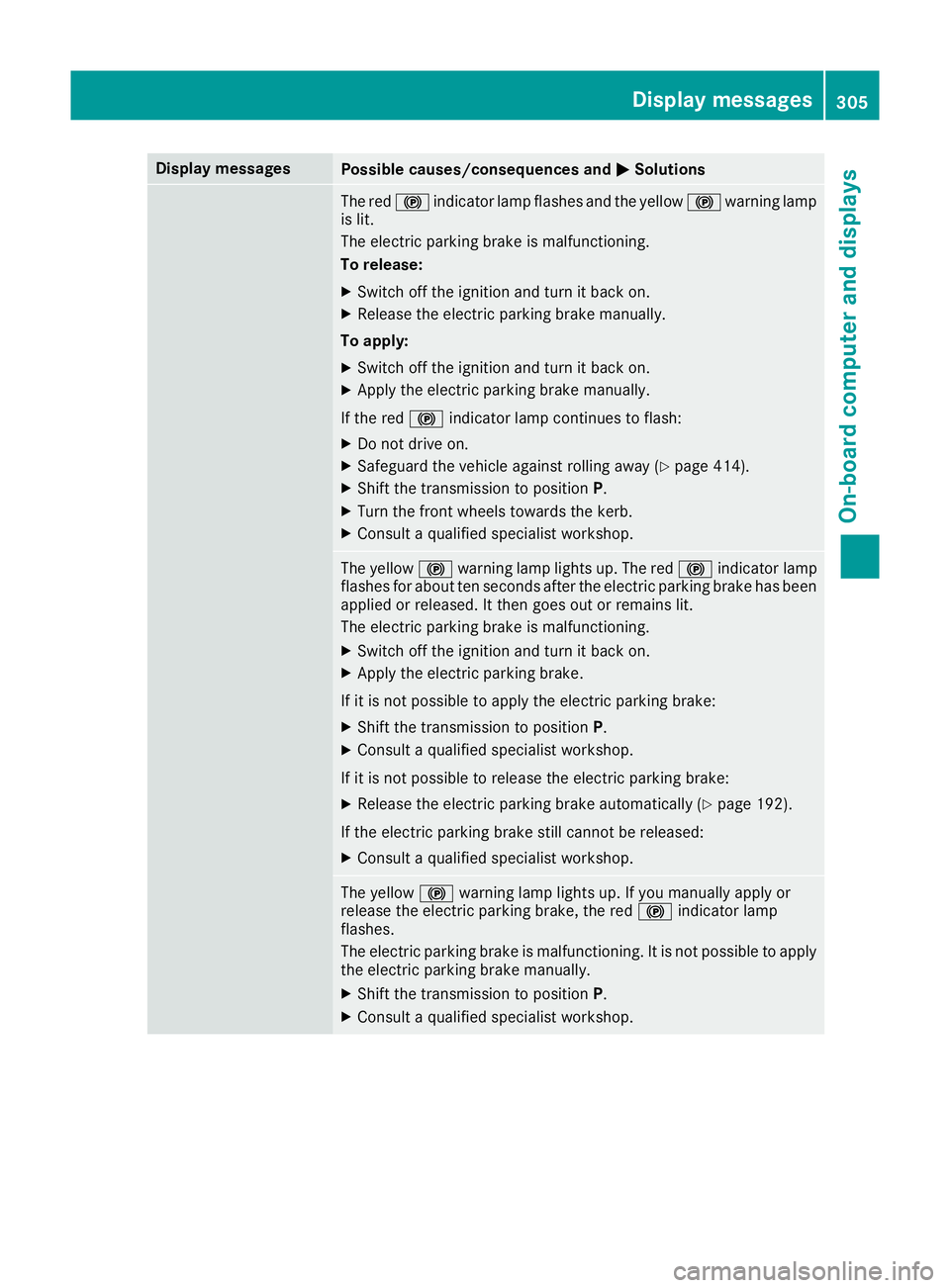
Display messages
Possible causes/consequences and
M
MSolutions The red
!indicator lamp flashes and the yellow !warning lamp
is lit.
The electric parking brake is malfunctioning.
To release:
X Switch off the ignition and turn it back on.
X Release the electric parking brake manually.
To apply: X Switch off the ignition and turn it back on.
X Apply the electric parking brake manually.
If the red !indicator lamp continues to flash:
X Do not drive on.
X Safeguard the vehicle against rolling away (Y page 414).
X Shift the transmission to position P.
X Turn the front wheels towards the kerb.
X Consult a qualified specialist workshop. The yellow
!warning lamp lights up. The red !indicator lamp
flashes for about ten seconds after the electric parking brake has been applied or released. It then goes out or remains lit.
The electric parking brake is malfunctioning.
X Switch off the ignition and turn it back on.
X Apply the electric parking brake.
If it is not possible to apply the electric parking brake:
X Shift the transmission to position P.
X Consult a qualified specialist workshop.
If it is not possible to release the electric parking brake:
X Release the electric parking brake automatically (Y page 192).
If the electric parking brake still cannot be released:
X Consult a qualified specialist workshop. The yellow
!warning lamp lights up. If you manually apply or
release the electric parking brake, the red !indicator lamp
flashes.
The electric parking brake is malfunctioning. It is not possible to apply
the electric parking brake manually.
X Shift the transmission to position P.
X Consult a qualified specialist workshop. Display
messages
305On-board computer and displays Z