2015 MERCEDES-BENZ GLE SUV tow
[x] Cancel search: towPage 188 of 453
Heat generated by the charging cable
and charging cable connector Observe the "Important safety notes"
(Y
page 182).
During the charging process, the charging cable
and charging cable connector may heat up.
The charging cable and the charging cable con- nector will only heat up within the permissible
limiting values, provided that:
R the mains power supply and the charging
cable are not damaged
R the instructions for handling the charging
cable and controls on the charging cable are
observed
If the charging cable or charging cable connec-
tor become too hot, have the mains power sup- ply checked.
Protection against overvoltage !
Voltage surges in the mains supply can dam-
age the vehicle. The vehicle is therefore
equipped with a device which protects it from
voltage surges in the mains supply. This
device may be triggered during severe thun-
derstorms, for example, and may lead to the
building's fuse being tripped and an interrup-
tion in the power supply. These functions pro-
tect the vehicle. After the building fuse is
switched on again, the charging process
resumes automatically. Following an interrup-
tion in the power supply or tripping of the
building's fuse, it may take up to 10 minutes
for charging to resume automatically.
Reset the building's circuit breaker. Otherwise,
the charging process cannot be continued.
General information on the charging
process Observe the "Important safety notes"
(Y page 182).
The vehicle socket is located in the rear bumper on the right below the tail lamp.
The charge socket flap and the vehicle are cen-
trally locked or unlocked simultaneously. Charging the high-voltage battery via
the mains socket
Charging cable for mains sockets Important safety notes
! Only use the charging cable to charge the
high-voltage battery. Do not use the charging cable for other purposes. It may otherwise be damaged.
The vehicle is supplied with a country-specific
charging cable, variant 1 or variant 2, for con-
nection to a mains socket. The controls of the
two charging cable variants are different. Only
use the charging cable supplied with the vehicle
or a charging cable approved for the vehicle.
i The charging process can vary depending on
the mains power supply. Therefore, always
observe the local information.
i For short charge times (charging with 16
A),
connect the fast-charging cable to a wallbox
or charging station without a preinstalled
cable. You can also use the optionally availa-
ble charging cable with the CE plug.
Information about charging from a wallbox
(Y page 188).
Information about charging from a charging sta-
tion (Y page 189).
Stowing the charging cable The charging cable can be stowed and secured
in the bag provided in the luggage compartment
of the vehicle.
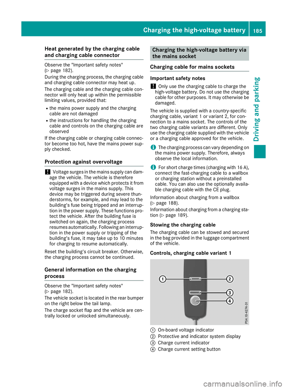
Controls, charging cable variant 1 :
On-board voltage indicator
; Protective and indicator system display
= Charge current indicator
? Charge current setting button Charging the high-voltage battery
185Driving and parking Z
Page 191 of 453
i
If the indicator lamps are off, lock or unlock
the vehicle. The indicator lamps will then dis- play the current status of the charging proc-
ess again.
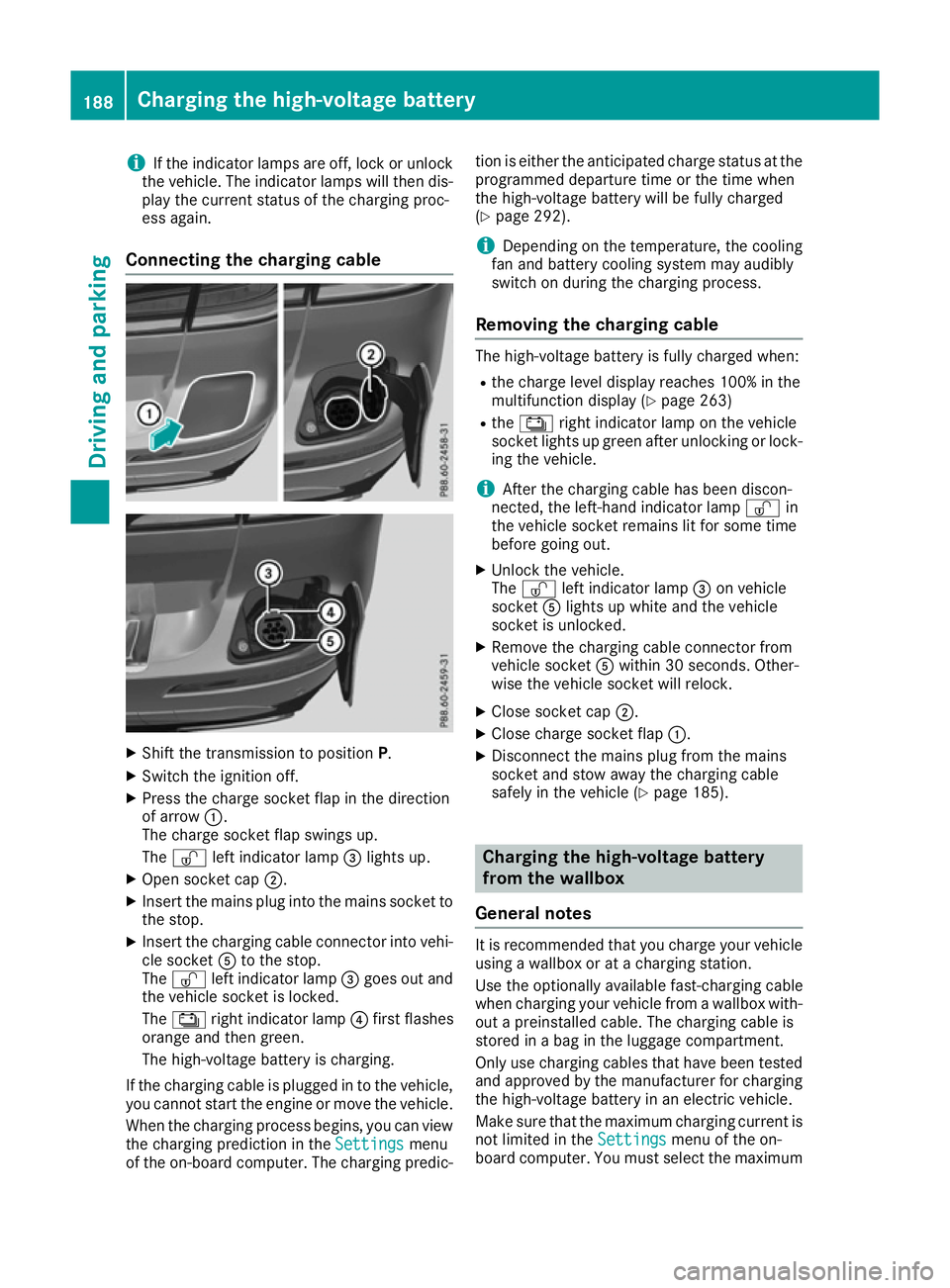
Connecting the charging cable X
Shift the transmission to position P.
X Switch the ignition off.
X Press the charge socket flap in the direction
of arrow :.
The charge socket flap swings up.
The Ì left indicator lamp =lights up.
X Open socket cap ;.
X Insert the mains plug into the mains socket to
the stop.
X Insert the charging cable connector into vehi-
cle socket Ato the stop.
The Ì left indicator lamp =goes out and
the vehicle socket is locked.
The Ý right indicator lamp ?first flashes
orange and then green.
The high-voltage battery is charging.
If the charging cable is plugged in to the vehicle,
you cannot start the engine or move the vehicle.
When the charging process begins, you can viewthe charging prediction in the Settings
Settings menu
of the on-board computer. The charging predic- tion is either the anticipated charge status at the
programmed departure time or the time when
the high-voltage battery will be fully charged
(Y page 292).
i Depending on the temperature, the cooling
fan and battery cooling system may audibly
switch on during the charging process.
Removing the charging cable The high-voltage battery is fully charged when:
R
the charge level display reaches 100% in the
multifunction display (Y page 263)
R the Ý right indicator lamp on the vehicle
socket lights up green after unlocking or lock-
ing the vehicle.
i After the charging cable has been discon-
nected, the left-hand indicator lamp Ìin
the vehicle socket remains lit for some time
before going out.
X Unlock the vehicle.
The Ì left indicator lamp =on vehicle
socket Alights up white and the vehicle
socket is unlocked.
X Remove the charging cable connector from
vehicle socket Awithin 30 seconds. Other-
wise the vehicle socket will relock.
X Close socket cap ;.
X Close charge socket flap :.
X Disconnect the mains plug from the mains
socket and stow away the charging cable
safely in the vehicle (Y page 185). Charging the high-voltage battery
from the wallbox
General notes It is recommended that you charge your vehicle
using a wallbox or at a charging station.
Use the optionally available fast-charging cable
when charging your vehicle from a wallbox with- out a preinstalled cable. The charging cable is
stored in a bag in the luggage compartment.
Only use charging cables that have been tested
and approved by the manufacturer for charging
the high-voltage battery in an electric vehicle.
Make sure that the maximum charging current is
not limited in the Settings Settingsmenu of the on-
board computer. You must select the maximum 188
Charging the high-voltage batteryDriving and parking
Page 192 of 453
value if charging at a wallbox or a charging sta-
tion (Y page 292).
Observe the "Important safety notes"
(Y page 182).
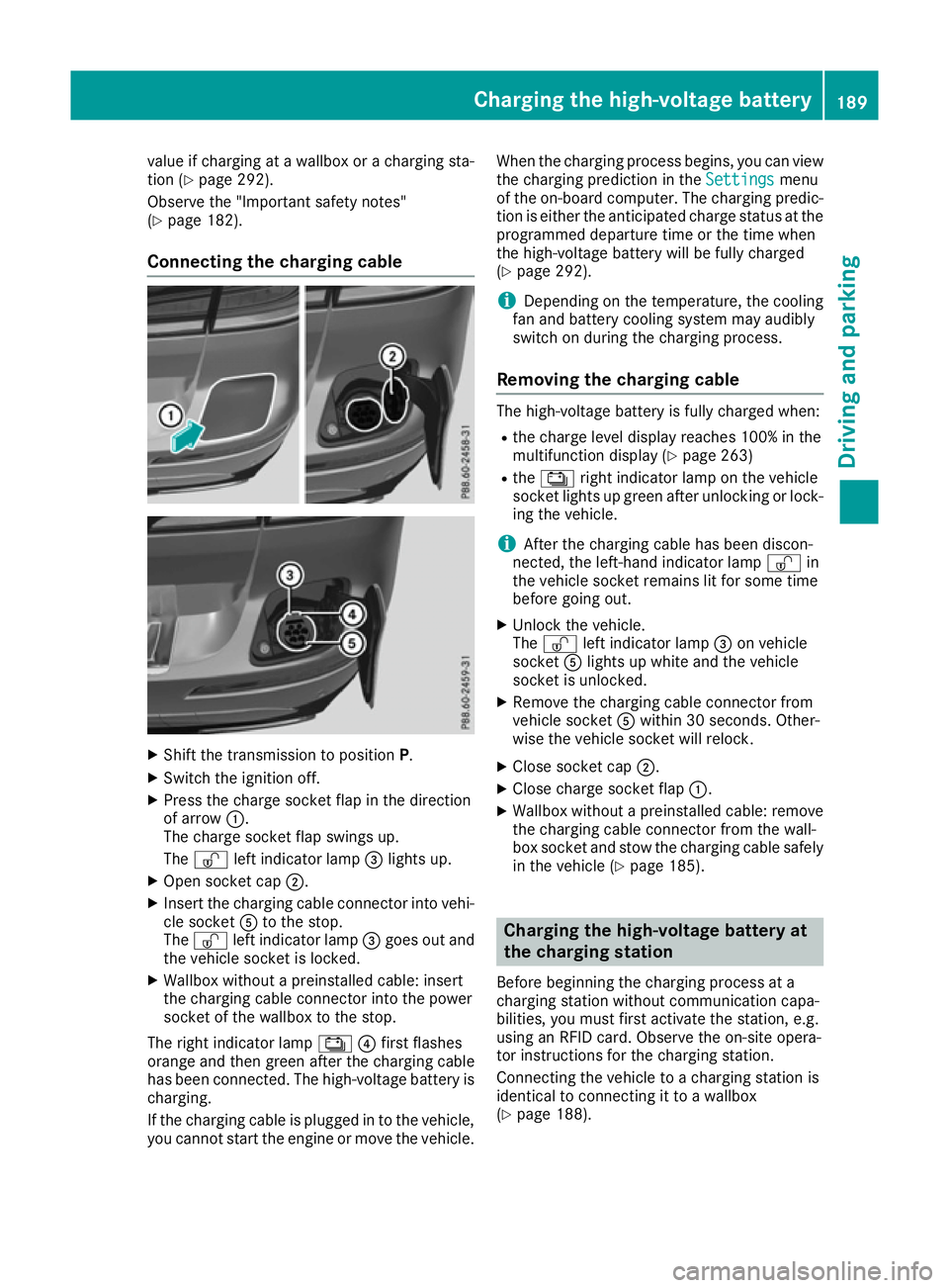
Connecting the charging cable X
Shift the transmission to position P.
X Switch the ignition off.
X Press the charge socket flap in the direction
of arrow :.
The charge socket flap swings up.
The Ì left indicator lamp =lights up.
X Open socket cap ;.
X Insert the charging cable connector into vehi-
cle socket Ato the stop.
The Ì left indicator lamp =goes out and
the vehicle socket is locked.
X Wallbox without a preinstalled cable: insert
the charging cable connector into the power
socket of the wallbox to the stop.
The right indicator lamp Ý?first flashes
orange and then green after the charging cable
has been connected. The high-voltage battery is charging.
If the charging cable is plugged in to the vehicle,
you cannot start the engine or move the vehicle. When the charging process begins, you can view
the charging prediction in the Settings
Settings menu
of the on-board computer. The charging predic-
tion is either the anticipated charge status at the
programmed departure time or the time when
the high-voltage battery will be fully charged
(Y page 292).
i Depending on the temperature, the cooling
fan and battery cooling system may audibly
switch on during the charging process.
Removing the charging cable The high-voltage battery is fully charged when:
R
the charge level display reaches 100% in the
multifunction display (Y page 263)
R the Ý right indicator lamp on the vehicle
socket lights up green after unlocking or lock-
ing the vehicle.
i After the charging cable has been discon-
nected, the left-hand indicator lamp Ìin
the vehicle socket remains lit for some time
before going out.
X Unlock the vehicle.
The Ì left indicator lamp =on vehicle
socket Alights up white and the vehicle
socket is unlocked.
X Remove the charging cable connector from
vehicle socket Awithin 30 seconds. Other-
wise the vehicle socket will relock.
X Close socket cap ;.
X Close charge socket flap :.
X Wallbox without a preinstalled cable: remove
the charging cable connector from the wall-
box socket and stow the charging cable safely in the vehicle (Y page 185). Charging the high-voltage battery at
the charging station
Before beginning the charging process at a
charging station without communication capa-
bilities, you must first activate the station, e.g.
using an RFID card. Observe the on-site opera-
tor instructions for the charging station.
Connecting the vehicle to a charging station is
identical to connecting it to a wallbox
(Y page 188). Charging the high-voltage battery
189Driving and parking Z
Page 194 of 453
Problem
Possible causes/consequences and
M
MSolutions The charging cable con-
nector cannot be
removed from the vehi-
cle socket. The charging cable connector has not been unlocked.
X Press the %button on the key.
The Ì indicator lamp on the vehicle socket lights up. The charg-
ing cable connector is unlocked.
X Remove the charging cable connector from the vehicle socket. The charging cable connector is blocked.
X Pull the charging cable close enough to the charging cable connec-
tor so that the charging cable connector is not under strain.
X Lock the vehicle and unlock it again.
X Remove the charging cable connector from the vehicle socket.
X If the charging cable connector continues to be blocked, consult a
qualified specialist workshop. Parking
Important safety notes
G
WARNING
Flammable material such as leaves, grass or
twigs may ignite if they come into contact with hot parts of the exhaust system or exhaust
gas flow. There is a risk of fire.
Park the vehicle so that no flammable mate-
rial can come into contact with hot vehicle
components. In particular, do not park on dry grassland or harvested grain fields. G
WARNING
If you leave children unattended in the vehi-
cle, they may be able to set the vehicle in
motion if, for example, they:
R release the parking brake
R shift the automatic transmission out of park
position P
R start the engine
In addition, they may operate vehicle equip-
ment and become trapped. There is a risk of
an accident and injury.
When leaving the vehicle, always take the key
with you and lock the vehicle. Never leave
children unattended in the vehicle. !
Always secure the vehicle correctly against
rolling away. Otherwise, the vehicle or its driv-
etrain could be damaged.
To ensure that the vehicle is safeguarded
against rolling away unintentionally:
R the electric parking brake must be applied.
R the transmission must be in position Pand the
key must be removed from the ignition lock
R the front wheels must be turned towards the
kerb on steep uphill or downhill gradients
R the empty vehicle must be secured at the
front axle with a wheel chock or similar
object, for example, on uphill or downhill gra-
dients
R a laden vehicle must also be secured at the
rear axle with a wheel chock or similar object,
for example, on uphill or downhill gradients Switching off the engine
Important safety notes G
WARNING
The automatic transmission switches to neu-
tral position Nwhen you switch off the engine.
The vehicle may roll away. There is a risk of an
accident.
After switching off the engine, always switch
to parking position P. Prevent the parked vehi-
cle from rolling away by applying the parking
brake. Parking
191Driving and parking Z
Page 195 of 453
Using the key
X
Apply the electric parking brake.
X Shift the transmission to position P.
X Turn the key to position 0in the ignition lock
and remove it.
The immobiliser is activated.
If you switch the engine off with the transmis-
sion in position Ror D, the automatic transmis-
sion shifts to Nautomatically.
If you then open the driver's door or the front-
passenger door or remove the key from the igni- tion, the automatic transmission shifts to P.
If you want the automatic transmission to
remain in neutral N, e.g. when having the vehicle
cleaned in an automatic car wash with a towing
system:
X Switch the ignition on.
X Depress the brake pedal and keep it
depressed.
X Shift to neutral N.
X Release the brake pedal.
X Release the electric parking brake.
X Switch off the ignition and leave the key in the
ignition lock.
Using KEYLESS-GO X
Apply the electric parking brake.
X Shift the transmission to position P.
X Press the Start/Stop button (Y page 158).
The engine stops and all the indicator lamps in the instrument cluster go out.
If you switch the engine off with the transmis-
sion in position Ror D, the automatic transmis-
sion shifts to Nautomatically.
If you then open the driver's or front-passenger door, the automatic transmission shifts to P.
If you want the automatic transmission to
remain in neutral N, e.g. when having the vehicle
cleaned in an automatic car wash with a towing
system:
X Remove the Start/Stop button from the igni-
tion lock.
X Insert the key into the ignition lock.
X Switch the ignition on.
X Depress the brake pedal and keep it
depressed.
X Shift to neutral N. X
Release the brake pedal.
X Release the electric parking brake.
X Switch off the ignition and leave the key in the
ignition lock.
i The engine can be switched off while the
vehicle is in motion by pressing and holding
the Start/Stop button for about three sec-
onds. This function operates independently of
the ECO start/stop automatic engine switch-
off function. Electric parking brake
General notes G
WARNING
If you leave children unattended in the vehi-
cle, they may be able to set the vehicle in
motion if, for example, they:
R release the parking brake
R shift the automatic transmission out of park
position P
R start the engine
In addition, they may operate vehicle equip-
ment and become trapped. There is a risk of
an accident and injury.
When leaving the vehicle, always take the key
with you and lock the vehicle. Never leave
children unattended in the vehicle.
The function of the electric parking brake is
dependent on the on-board voltage. If the on-
board voltage is low or if there is a malfunction
in the system, it may not be possible to apply the
released parking brake.
X If this is the case, only park the vehicle on
level ground and secure it to prevent it from
rolling away.
X Shift the automatic transmission to position
P.
It may not be possible to release an applied
parking brake if the on-board voltage is low or if there is a malfunction in the system. Contact a
qualified specialist workshop.
i The electric parking brake carries out a func-
tion check at regular intervals when the 192
ParkingDriving and parking
Page 203 of 453
The following driving systems are specially
adapted to off-road driving:
R the Offroad drive program (vehicles without
Off-Road Engineering package)
(Y page 254)
R Offroad andOffroad Plus drive programs
(vehicles with Off-Road Engineering pack-
age) . (Y page 254)
R LOW RANGE offroad gear (vehicles with the
Off-Road Engineering package)
(Y page 255)
R Differential lock (vehicles with the Off-Road
Engineering package) (Y page 255)
R Off-road ABS (Y page 71)
R Offroad 4ETS (Y page 76)
R Offroad ESP ®
(Y page 77)
R AIRMATIC package (vehicle level)
(Y page 220)
R DSR (Downhill Speed Regulation)
(Y page 252)
Observe the following notes:
R Stop the vehicle before driving off-road. If
necessary, select the offroad program
(Y page 254) or shift to the LOW RANGE off-
road gear (Y page 255).
R Select a vehicle level suitable for the off-road
terrain. To avoid damaging the vehicle, make sure there is always sufficient ground clear-
ance.
R Make sure that items of luggage and loads are
stowed safely and are well secured
(Y page 355).
R Always keep the engine running and in gear
when driving on a downhill gradient. Activate
DSR (Y page 252).
R Drive slowly and evenly, if necessary at walk-
ing pace.
R Ensure that the wheels are in contact with the
ground at all times.
R Drive with extreme care on unknown off-road
routes where visibility is poor. For safety rea-
sons, get out of the vehicle first and survey
the off-road route.
R Look out for obstacles such as rocks, holes,
tree stumps and furrows.
R Take care when turning on an uphill or down-
hill slope or when driving across a slope. The
vehicle could otherwise tip over. R
Always keep the doors, the tailgate and the
sliding sunroof closed while the vehicle is in
motion.
R Do not stray from marked routes or paths.
R Observe the notes on off-road fording
(Y page 198).
i Information about retrofitting special all-ter-
rain tyres is available from any qualified spe-
cialist workshop.
i Do not use the HOLD function when driving
off-road, on steep uphill or downhill gradients or on slippery or loose surfaces. The HOLD
function cannot hold the vehicle on such sur-faces.
Checklist before driving off-road X
Engine oil level: check the engine oil and top
it up if necessary.
When driving on steep gradients, the oil level must be sufficiently high to ensure a correct
oil supply in the vehicle.
X AdBlue ®
tank (BlueTEC vehicles): check
the level and top up if necessary
(Y page 180).
X Tyre-change tool kit: check that the jack is
working and make sure you have the wheel
wrench, a robust tow cable and a folding
spade in the vehicle.
X Wheels and tyres: check the tyre tread
depth and tyre pressure.
X Check for damage and remove any foreign
objects, e.g. small stones, from the wheels/
tyres.
X Replace any missing valve caps.
X Replace dented or damaged wheels.
X Wheels: dented or bent wheels can lead to a
loss of tyre pressure and damage to the tyre
bead. Before driving off-road, check the
wheels and replace them if necessary.
Checklist after driving off-road !
If you detect damage to the vehicle after
driving off-road, have the vehicle checked
immediately at a qualified specialist work-
shop.
Driving over rough terrain places greater
demands on your vehicle than driving on normal
roads. After driving off-road, check the vehicle.
This allows you to detect damage promptly and 200
Driving tipsDriving and parking
Page 206 of 453
vehicle is facing in the direction of the line of
fall.
R Check that the brakes are working normally
after a long downhill stretch.
i Off-road ABS is activated when the off-road
program is selected.
At speeds below 30 km/h the front wheels
lock cyclically during braking. The digging-in
effect achieved in the process reduces the
stopping distance when driving off-road. The
steerability of the vehicle is considerably
reduced if the wheels lock. Driving systems
Intelligent Drive
Mercedes-Benz Intelligent Drive stands for inno- vative driver assistance and safety systems
which enhance comfort and support the driver in
critical situations. With these intelligent co-ordi- nated systems Mercedes-Benz has set a mile-
stone on the path towards autonomous driving.
Mercedes-Benz Intelligent Drive embraces all
elements of active and passive safety in one well thought-out system – for the safety of the vehi-
cle occupants and that of other road users.
Further information on driving safety systems
(Y page 70). Cruise control
General notes Cruise control maintains a constant road speed
for you. It brakes automatically in order to avoid
exceeding the set speed. You must select a
lower gear in good time on long and steep down-
hill gradients, especially if the vehicle is laden or towing a trailer. By doing so, you will make use of
the braking effect of the engine. This relieves the load on the brake system and prevents the
brakes from overheating and wearing too
quickly.
Use cruise control only if road and traffic con-
ditions are appropriate for maintaining a steady
speed for a prolonged period. You can store any road speed above 30 km/h. Important safety notes If you fail to adapt your driving style, cruise con-
trol can neither reduce the risk of an accident
nor override the laws of physics. Cruise control
cannot take into account road, weather or traffic conditions. Cruise control is only an aid. You are
responsible for the distance to the vehicle in
front, for vehicle speed, for braking in good time, and for staying in lane.
Do not use cruise control:
R in road and traffic conditions which do not
allow you to maintain a constant speed (e.g. in
heavy traffic or on winding roads)
R on smooth or slippery roads. Braking or accel-
erating can cause the drive wheels to lose
traction and the vehicle could then skid
R when there is poor visibility, e.g. due to fog,
heavy rain or snow
If there is a change of drivers, advise the new
driver of the speed stored.
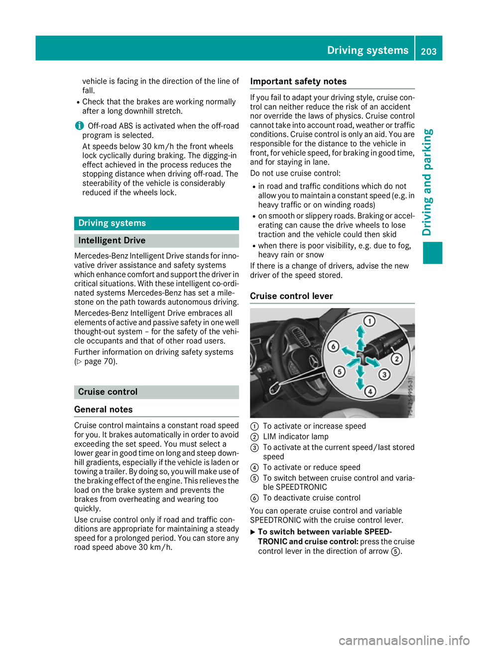
Cruise control lever :
To activate or increase speed
; LIM indicator lamp
= To activate at the current speed/last stored
speed
? To activate or reduce speed
A To switch between cruise control and varia-
ble SPEEDTRONIC
B To deactivate cruise control
You can operate cruise control and variable
SPEEDTRONIC with the cruise control lever.
X To switch between variable SPEED-
TRONIC and cruise control:
press the cruise
control lever in the direction of arrow A. Driving systems
203Driving and parking Z
Page 207 of 453
LIM indicator lamp
;on the cruise control lever
indicates which function you have selected:
R LIM indicator lamp ;
;off: cruise control is
selected
R LIM indicator lamp ;
; on: variable SPEED-
TRONIC is selected
When you activate cruise control, the stored
speed is shown in the multifunction display for
five seconds. In addition, the ésymbol
appears in the multifunction display.
Speedometer with segments: when cruise
control is activated, the segments from the
stored speed to the maximum permitted speed
light up.
Selecting cruise control X
Check whether LIM indicator lamp ;is off.
If it is off, cruise control is already selected.
If it is not, press the cruise control lever in the
direction of arrow A.
LIM indicator lamp ;in the cruise control
lever goes out. Cruise control is selected.
Activation conditions To activate cruise control, all of the following
activation conditions must be fulfilled:
R the electric parking brake must be released.
R you are driving faster than 30 km/h.
R ESP ®
must be switched on, but not interven-
ing.
R the transmission must be in position D.
R DSR must be deactivated.
R the Offroad Plus drive program must be deac-
tivated (vehicles with the Off-Road Engineer-
ing package).
R the cruise control function must be selected
(Y page 204).
Storing, maintaining and calling up a
speed Storing and maintaining the speed
X Accelerate the vehicle to the desired speed.
X Briefly press the cruise control lever up :or
down ?.
X Remove your foot from the accelerator pedal.
Cruise control is activated. The vehicle auto-
matically maintains the stored speed. i
Cruise control may be unable to maintain
the stored speed on uphill gradients. The
stored speed is resumed when the gradient
evens out. Cruise control maintains the
stored speed on downhill gradients by auto-
matically braking the vehicle.
Storing or calling up the speed G
WARNING
If you call up a stored speed and this is dif-
ferent from the current speed, the vehicle
accelerates or brakes. If you do not know
what the stored speed is, the vehicle may
accelerate or brake unexpectedly. There is a
risk of an accident.
Take the traffic conditions into account
before calling up the stored speed. If you do
not know what the stored speed is, store the
desired speed again.
X Briefly pull the cruise control lever towards
you =.
X Remove your foot from the accelerator pedal.
Cruise control is on and, when activated for
the first time, accepts the current speed or it
adjusts the vehicle's speed to the speed
stored.
Setting a speed Bear in mind that it may take a brief moment
until the vehicle has accelerated or braked to
the set speed.
X Press the cruise control lever up :for a
higher speed or down ?for a lower speed.
X Keep the cruise control lever pressed until the
desired speed is reached.
X Release the cruise control lever.
The new speed is stored.
X To adjust the set speed in 1 km/h incre-
ments:
briefly press the cruise control lever
up : or down ?to the pressure point.
The last stored speed increases or decreases
in 1 km/h increments.
X To adjust the set speed in 10 km/h incre-
ments: briefly press the cruise control lever
up : or down ?beyond the pressure point.
The last stored speed increases or decreases
in 10 km/h increments. 204
Driving systemsDriving and parking