Page 249 of 274

Do not overload the tires by exceeding the
specified load limit. The maximum permissi-
ble load can be found on the vehicle's Tire andLoading Information placard on the B-pillar on
the driver's side ( Ypage 238).
iThe actual values for tires are vehicle-
specific and may deviate from the values in
the illustration.
DOT, Tire Identification Number (TIN)
U.S. tire regulations prescribe that every
manufacturer of new tires or retreader has to imprint a TIN in or on the sidewall of each tire produced.
The TIN is a unique identification number. The
TIN enables tire manufacturers to inform pur-
chasers of recalls and other safety-relevant
matters. It makes it possible for the pur-
chaser to easily identify the affected tires.
The TIN is made up of manufacturer identifi-
cation code ;, tire size =, tire type code ?
and manufacturing date A.
DOT (Department of Transportation): tire
symbol :indicates that the tire complies
with the requirements of the U.S. Department of Transportation.
Manufacturer identification code: manu-
facturer identification code ;provides
details on the tire manufacturer. New tires
have a code with two symbols. Retreaded
tires have a code with four symbols.
For further information about retreaded tires,
see ( Ypage 230). Tire size:
identifier=describes the tire size.
Tire type code: tire type code?can be used
by the manufacturer as a code to describe
specific characteristics of the tire.
Date of manufacture: date of manufacture
A provides information about the age of a
tire. The first and second positions represent
the week of manufacture, starting with "01"
for the first calendar week. Positions three
and four represent the year of manufacture.
For example, a tire that is marked with
"3208", was manufactured in week 32 in
2008.
iTire data is vehicle-specific and may devi-
ate from the data in the example.
Tire characteristics
This information describes the type of tire
cord and the number of layers in sidewall :
and under tire tread ;.
iTire data is vehicle-specific and may devi-
ate from the data in the example.
Definition of terms for tires and load-
ing
Tire ply composition and material used
Describes the number of layers or the number
of rubber-coated belts in the tread and the
sidewall of the tire. These are made of steel,
nylon, polyester and other materials.
Tire labeling247
Wheels and tires
Z
Page 250 of 274
 and 100 kilopascals
(kPa) are the equivalent of 1 bar.
DOT (Department of Transportation)
DOT-marked tires fulfill the requireme")
Bar
Metric unit for tire pressure. 14.5038 poundsper square inch (psi) and 100 kilopascals
(kPa) are the equivalent of 1 bar.
DOT (Department of Transportation)
DOT-marked tires fulfill the requirements of
the U S Department of Transportation.
Normal occupant weight
The number of occupants for which the vehi-
cle is designed multiplied by 68 kilograms
(150 lbs).
Uniform Tire Quality Grading Standards
A uniform standard to grade the quality of
tires with regards to tread quality, tire traction
and temperature characteristics. The quality
grading assessment is made by the manufac- turer following specifications from the U.S.
government. The ratings are molded into the
sidewall of the tire.
Recommended tire pressures
The recommended tire pressure applies to
the tires mounted at the factory.
The Tire and Loading Information placard con- tains the recommended tire pressures for
cold tires on a fully loaded vehicle and for the
maximum permissible vehicle speed.
The tire pressure table contains the recom-
mended pressures for cold tires for various
operating conditions, i.e. differing load and
speed conditions.
Increased vehicle weight due to
optional equipment
The combined weight of all standard and
optional equipment available for the vehicle,
regardless of whether it is actually installed
on the vehicle or not.
Rim
This is the part of the wheel on which the tire
is mounted.
GAWR (Gross Axle Weight Rating)
The GAWR is the maximum gross axle weight rating. The actual load on an axle must never
exceed the gross axle weight rating. The
gross axle weight rating can be found on the
vehicle identification plate on the B-pillar on
the driver's side.
Speed rating
The speed rating is part of the tire identifica-
tion. It specifies the speed range for which the
tire is approved.
GTW (Gross Trailer Weight)
The GTW is the weight of a trailer including the weight of the load, luggage, accessories etc.
on the trailer.
GVW (Gross Vehicle Weight)
The gross vehicle weight includes the weight
of the vehicle including fuel, tools, the spare
wheel, accessories installed, occupants, lug-
gage and the drawbar noseweight, if applica-
ble. The gross vehicle weight must not exceed the gross vehicle weight rating GVWR as
specified on the vehicle identification plate on
the B-pillar on the driver's side.
GVWR (Gross Vehicle Weight Rating)
The GVWR is the maximum permissible gross
weight of a fully loaded vehicle (the weight of the vehicle including all accessories, occu-
pants, fuel, luggage and the drawbar nose-
weight, if applicable). The gross vehicle
weight rating is specified on the vehicle iden-
tification plate on the B-pillar on the driver's
side.
248Tire labeling
Wheels and tires
Page 251 of 274

Maximum loaded vehicle weight
The maximum weight is the sum of: Rthe curb weight of the vehicle
R the weight of the accessories
R the load limit
R the weight of the factory installed optional
equipment
Kilopascal (kPa)
Metric unit for tire pressure. 6.9 kPa corre-
sponds to 1 psi. Another unit for tire pressure
is bar. 100 kilopascals (kPa) are the equiva-
lent of 1 bar.
Load index
In addition to the load-bearing index, the load index may also be imprinted on the sidewall of
the tire. This specifies the load-bearing capa- city more precisely.
Curb weight
The weight of a vehicle with standard equip-
ment including the maximum capacity of fuel,oil and coolant. It also includes the air-condi- tioning system and optional equipment if
these are installed in the vehicle, but does notinclude passengers or luggage.
Maximum load rating
The maximum load rating is the maximum
permissible weight in kilograms or lbs for
which a tire is approved.
Maximum permissible tire pressure
Maximum permissible tire pressure for one tire.
Maximum load on one tire
Maximum load on one tire. This is calculated
by dividing the maximum axle load of one axleby two.
PSI (pounds per square inch)
A standard unit of measure for tire pressure.
Aspect ratio
Relationship between tire height and tire
width in percent.
Tire pressure
This is pressure inside the tire applying an
outward force to each square inch of the tire's surface. The tire pressure is specified in
pounds per square inch (psi), in kilopascals
(kPa) or in bar. The tire pressure should only
be corrected when the tires are cold.
Cold tire pressure
The tires are cold:
R if the vehicle has been parked without
direct sunlight on the tires for at least three
hours and
R if the vehicle has not been driven further
than 1 mile (1.6 km)
Tread
The part of the tire that comes into contact
with the road.
Bead
The tire bead ensures that the tire sits
securely on the wheel. There are several steel
wires in the bead to prevent the tire from
coming loose from the wheel rim.
Sidewall
The part of the tire between the tread and the
bead.
Weight of optional extras
The combined weight of those optional extras
that weigh more than the replaced standard
parts and more than 2.3 kg (5 lbs). These
optional extras, such as high-performance
Tire labeling249
Wheels and tires
Z
Page 252 of 274

This is a unique identifier")
brakes, level control, a roof rack or a high-
performance battery, are not included in the
curb weight and the weight of the accesso-ries.
TIN (Tire Identification Number)
This is a unique identifier which can be used
by a tire manufacturer to identify tires, for
example for a product recall, and thus identifythe purchasers. The TIN is made up of the
manufacturer's identity code, tire size, tire
type code and the manufacturing date.
Load bearing index
The load bearing index (also load index) is a
code that contains the maximum load bearing capacity of a tire.
Traction
Traction is the result of friction between the
tires and the road surface.
TWR (Tongue Weight Rating)
The TWR specifies the maximum permissible
weight that the ball coupling of the trailer tow hitch can support.
Treadwear indicators
Narrow bars (tread wear bars) that are dis-
tributed over the tire tread. If the tire tread islevel with the bars, the wear limit of áin
(1.6 mm) has been reached.
Occupant distribution
The distribution of occupants in a vehicle at
their designated seating positions.
Total load limit
Nominal load and luggage load plus 150 lb
(68 kilograms) multiplied by the number of
seats in the vehicle.
Changing a wheel
Flat tire
The "Breakdown assistance" section ( Y page 216) contains information and notes
on how to deal with a flat tire.
Rotating the wheels
GWARNING
Interchanging the front and rear wheels may
severely impair the driving characteristics if
the wheels or tires have different dimensions. The wheel brakes or suspension components
may also be damaged. There is a risk of acci-
dent.
Rotate front and rear wheels only if the wheels and tires are of the same dimensions.
!On vehicles equipped with a tire pressure
monitor, electronic components are loca-
ted in the wheel.
Tire-mounting tools should not be used
near the valve. This could damage the elec- tronic components.
Only have tires changed at a qualified spe-cialist workshop.
Rotating front and rear wheels of differing
dimensions can render the general operating
permit invalid.
Always pay attention to the instructions and
safety notices in the section on "Changing a
wheel and mounting a spare wheel"( Y page 251).
The wear patterns on the front and rear tires
differ, depending on the operating conditions.
Rotate the wheels before a clear wear pattern has formed on the tires. Front tires typically
wear more on the shoulders and the rear tires in the center.
If your vehicle's tire configuration allows, you can rotate the wheels according to the inter-
vals in the tire manufacturer's warranty book
in your vehicle documents. If no warranty
book is available, the tires should be rotated
250Changing a wheel
Wheels and tires
Page 253 of 274
, or earlier if tire wear
requires. Do not change the direction of
wheel rotation.
Clean the contact surfaces of the wheel and
the brake disc thorough")
every 3,000 to 6,000 miles
(5,000 to 10,000 km), or earlier if tire wear
requires. Do not change the direction of
wheel rotation.
Clean the contact surfaces of the wheel and
the brake disc thoroughly every time a wheel
is rotated. Check the tire pressure and reac-
tivate the tire pressure monitor ( Ypage 235)
if necessary.
Direction of rotation
Tires with a specified direction of rotation
have additional benefits, e.g. if there is a risk
of hydroplaning. You will only gain these ben-
efits if the correct direction of rotation isobserved.
An arrow on the sidewall of the tire indicates
its correct direction of rotation.
You may mount the spare wheel against the
direction of rotation. Adhere to the time
restriction on use as well as the speed limi-
tation specified on the spare wheel.
Storing wheels
Store tires that are not being used in a cool,
dry and preferably dark place. Protect the
tires from oil, grease, gasoline and diesel.
Mounting a wheel
Preparing the vehicle
GWARNING
When you remove the spare wheel from the
spare wheel bracket, the vehicle’s weight dis- tribution changes. If the vehicle is already
raised, the jack could tip over. There is a risk
of injury.
Remove the spare wheel from the spare wheel
bracket before lifting the vehicle.
X Prepare the vehicle as described (Y page 216). X
Remove the vehicle tool kit and the jack(Y page 214).
X Secure the vehicle to prevent it from rolling
away.
X Remove the spare wheel from the spare
wheel bracket ( Ypage 215).
iVehicles without a spare wheel or emer-
gency spare wheel are not equipped with a tire-change tool kit at the factory. For more
information on which tools are required to
perform a wheel change on your vehicle
e.g. lug wrench or jack, consult an author-
ized Mercedes-Benz Center.
Securing the vehicle to prevent it from
rolling away
X On level ground: place chocks or other
suitable items under the front and rear of
the wheel that is diagonally opposite the
wheel you wish to change.
X On downhill gradients: place chocks or
other suitable items in front of the wheels
of the front and rear axle.
Raising the vehicle
GWARNING
If you do not position the jack correctly at the appropriate jacking point of the vehicle, the
jack could tip over with the vehicle raised.
There is a risk of injury.
Only position the jack at the appropriate jack-
ing point of the vehicle. The base of the jack
must be positioned vertically, directly under
the jacking point of the vehicle.
!The jack is designed exclusively for jack-
ing up the vehicle at the jacking points.
Otherwise, your vehicle could be damaged.
The following must be observed when raising
the vehicle:
R To raise the vehicle, only use the vehicle-
specific jack that has been tested and
approved by Mercedes-Benz. If used incor-
Changing a wheel251
Wheels and tires
Z
Page 254 of 274

rectly, the jack could tip over with the vehi-cle raised.
R The jack is designed only to raise and hold
the vehicle for a short time while a wheel
is being changed. It is not suited for per-
forming maintenance work under the vehi-
cle.
R Avoid changing the wheel on uphill and
downhill slopes.
R Before raising the vehicle, secure it from
rolling away by applying the parking brake
and inserting wheel chocks. Never disen-
gage the parking brake while the vehicle is
raised.
R The jack must be placed on a firm, flat and
non-slip surface. On a loose surface, a
large, load-bearing underlay must be used.
On a slippery surface, a non-slip underlay
must be used, e.g. rubber mats.
R Do not use wooden blocks or similar
objects as a jack underlay. Otherwise, the
jack will not be able to achieve its load-
bearing capacity due to the restricted
height.
R Make sure that the distance between the
underside of the tires and the ground does
not exceed 1.2 in (3 cm).
R Never place your hands and feet under the
raised vehicle.
R Never lie under the raised vehicle.
R Never start the engine when the vehicle is
raised.
R Never open or close a door or the tailgate
when the vehicle is raised.
R Make sure that no persons are present in
the vehicle when the vehicle is raised.
XUsing lug wrench :, loosen the bolts on
the wheel you wish to change by about one full turn. Do not unscrew the wheel bolts
completely.
Pump lever ;
X
Assemble the pump lever for the jack. It can
be found with the vehicle tool kit ( Y page 214).
252Changing a wheel
Wheels and tires
Page 255 of 274

XTurn pressure release screw =clockwise
as far as it will go using notch ;on the
pump lever.
Pressure release screw =is closed.
iDo not turn pressure release screw =by
more than one to two revolutions. Other-
wise, hydraulic fluid could escape.
X Set jack :on solid ground.
X Position jack :on the axle carrier tube ;
of the front or rear axle. Jack :must
always stand vertically, even on slopes.
Make sure that jack :is correctly posi-
tioned under axle carrier tube ;. The front
or rear axle must sit securely in the recess of jack :.
X Raise the vehicle by pumping in the direc-
tion of the arrow until the tire is 1.2 in
(3 cm) off the ground at the most.
Removing a wheel
!Do not place wheel bolts in sand or on a
dirty surface. The bolt and wheel hub
threads could otherwise be damaged when you screw them in.
X Unscrew the wheel bolts.
X Remove the wheel.
Mounting a new wheel
GWARNING
Oiled or greased wheel bolts/wheel nuts and
damaged wheel bolt/wheel nut/wheel hub
threads can cause wheel bolts/wheel nuts to come loose. As a result, you could lose a
wheel while driving. There is a risk of an acci- dent.
Never oil or grease wheel bolts/wheel nuts. In the event of damage to the threads, contact a
qualified specialist workshop immediately.
Have the damaged wheel bolts/wheel nuts or hub threads replaced/renewed. Do not con-
tinue driving.
GWARNING
If you tighten the wheel bolts or wheel nuts
when the vehicle is raised, the jack could tip
over. There is a risk of injury.
Only tighten the wheel bolts or wheel nuts
when the vehicle is on the ground.
!To prevent damage to the paintwork, hold
the wheel securely against the wheel hub
while screwing in the first wheel bolt.
Always pay attention to the instructions and
safety notes in the "Changing a wheel" sec-
tion ( Ypage 250).
X Clean the wheel and wheel hub contactsurfaces.
X Place the new wheel on the wheel hub and
push it on.
X Tighten the wheel bolts until they are fin-
ger-tight.
Lowering the vehicle
GWARNING
The wheels could work loose if the wheel nuts
and bolts are not tightened to the specified
tightening torque. There is a risk of accident.
Have the tightening torque immediately
checked at a qualified specialist workshop
after a wheel is changed.
Changing a wheel253
Wheels and tires
Z
Page 256 of 274
 by
approximately one turn.
X Lower the vehicle until it is once again
standing firmly on the ground.
X Place the jack to")
XOpen the pressure release screw on the
jack using the pump lever ( Ypage 251) by
approximately one turn.
X Lower the vehicle until it is once again
standing firmly on the ground.
X Place the jack to one side.
X Tighten the wheel bolts evenly in a cross-
wise pattern in the sequence indicated ( :
to A ). The specified tightening torque is
96 lb-ft (130 Nm).
X Disassemble the pump lever.
X Push the jack piston back in and close the
drain plug.
X Use the bolts to secure the faulty wheel to
the spare wheel bracket ( Ypage 215).
X Stow the jack and the vehicle tools in the
vehicle again.
X Check the tire pressure of the newly instal-
led wheel and adjust it if necessary.
A table with the tire pressures for your vehi-
cle can be found on the B-pillar on the driv-
er's side.
Wheel and tire combinations
General notes
GWARNING
If wheels and tires of the wrong size are used, the wheel brakes or suspension components
may be damaged. There is a risk of an acci-dent.
Always replace wheels and tires with those
that fulfill the specifications of the originalpart.
When replacing wheels, make sure to use the correct:
R designation
R model
When replacing tires, make sure to use the
correct:
R designation
R manufacturer
R model
GWarning
A flat tire severely impairs the driving, steer-
ing and braking characteristics of the vehicle.
There is a risk of an accident.
do not drive with a flat tire. Immediately
replace the flat tire with your spare wheel, or
consult a qualified specialist workshop.
!For safety reasons, Mercedes-Benz rec-
ommends that you only use tires, wheels
and accessories which have been approved by Mercedes-Benz specifically for your
vehicle. These tires have been specially
adapted for use with the driving safety sys-
tems, such as ABS or ESP ®
.
Only use tires, wheels or accessories tes-
ted and approved by Mercedes-Benz. Cer-
tain characteristics, e.g. handling, vehicle
noise emissions or fuel consumption, may
otherwise be adversely affected. In addi-
tion, when driving with a load, tire dimen-
sion variations could cause the tires to
come into contact with the bodywork and
axle components. This could result in dam-
age to the tires or the vehicle.
Mercedes-Benz accepts no liability for
damage resulting from the use of tires,
wheels or accessories other than those tes- ted and approved.
Further information about wheels, tires and
approved combinations can be obtained
254Wheel and tire combinations
Wheels and tires
 1
1 2
2 3
3 4
4 5
5 6
6 7
7 8
8 9
9 10
10 11
11 12
12 13
13 14
14 15
15 16
16 17
17 18
18 19
19 20
20 21
21 22
22 23
23 24
24 25
25 26
26 27
27 28
28 29
29 30
30 31
31 32
32 33
33 34
34 35
35 36
36 37
37 38
38 39
39 40
40 41
41 42
42 43
43 44
44 45
45 46
46 47
47 48
48 49
49 50
50 51
51 52
52 53
53 54
54 55
55 56
56 57
57 58
58 59
59 60
60 61
61 62
62 63
63 64
64 65
65 66
66 67
67 68
68 69
69 70
70 71
71 72
72 73
73 74
74 75
75 76
76 77
77 78
78 79
79 80
80 81
81 82
82 83
83 84
84 85
85 86
86 87
87 88
88 89
89 90
90 91
91 92
92 93
93 94
94 95
95 96
96 97
97 98
98 99
99 100
100 101
101 102
102 103
103 104
104 105
105 106
106 107
107 108
108 109
109 110
110 111
111 112
112 113
113 114
114 115
115 116
116 117
117 118
118 119
119 120
120 121
121 122
122 123
123 124
124 125
125 126
126 127
127 128
128 129
129 130
130 131
131 132
132 133
133 134
134 135
135 136
136 137
137 138
138 139
139 140
140 141
141 142
142 143
143 144
144 145
145 146
146 147
147 148
148 149
149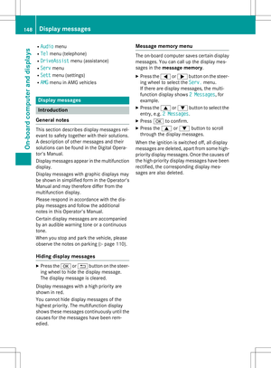 150
150 151
151 152
152 153
153 154
154 155
155 156
156 157
157 158
158 159
159 160
160 161
161 162
162 163
163 164
164 165
165 166
166 167
167 168
168 169
169 170
170 171
171 172
172 173
173 174
174 175
175 176
176 177
177 178
178 179
179 180
180 181
181 182
182 183
183 184
184 185
185 186
186 187
187 188
188 189
189 190
190 191
191 192
192 193
193 194
194 195
195 196
196 197
197 198
198 199
199 200
200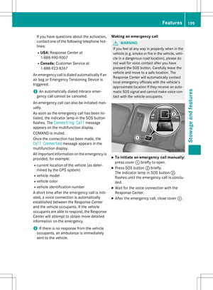 201
201 202
202 203
203 204
204 205
205 206
206 207
207 208
208 209
209 210
210 211
211 212
212 213
213 214
214 215
215 216
216 217
217 218
218 219
219 220
220 221
221 222
222 223
223 224
224 225
225 226
226 227
227 228
228 229
229 230
230 231
231 232
232 233
233 234
234 235
235 236
236 237
237 238
238 239
239 240
240 241
241 242
242 243
243 244
244 245
245 246
246 247
247 248
248 249
249 250
250 251
251 252
252 253
253 254
254 255
255 256
256 257
257 258
258 259
259 260
260 261
261 262
262 263
263 264
264 265
265 266
266 267
267 268
268 269
269 270
270 271
271 272
272 273
273