2015 MERCEDES-BENZ G-CLASS SUV wheel bolts
[x] Cancel search: wheel boltsPage 226 of 274

tion switch, the hazard warning lamp starts
flashing again.
X Turn the SmartKey to position 2in the igni-
tion lock ( Ypage 103).
X When the vehicle is stationary, depress the
brake pedal and keep it depressed.
X Shift the transfer case to neutral positionN (Y page 134).
X Shift the automatic transmission to posi-
tion N.
X Release the brake pedal.
X Release the parking brake ( Ypage 111).
iThe transmission can only change gear if
the battery has sufficient charge.
If you cannot move the selector lever to N,
the propeller shafts to the driven axles
must be removed.
Transporting the vehicle
!
You may only secure the vehicle by the
wheels, not by parts of the vehicle such as
axle or steering components. Otherwise,
the vehicle could be damaged.
Use the towing eyes to pull the vehicle if it
needs to be transported on a trailer or trans-
porter ( Ypage 223).
X Apply the parking brake.
X Turn the SmartKey to position 2in the igni-
tion lock ( Ypage 103).
X Shift the selector lever to N.
X Shift the transfer case to neutral
( Y page 134).
X Secure the towing cable to the towing eyes
( Y page 223).
X Make sure that the vehicle cannot roll
away.
X Release the parking brake.
X Load the vehicle onto the transporter. As soon as the vehicle has been loaded: X
Apply the parking brake.
X Shift the automatic transmission to posi-
tion P.
X Turn the SmartKey to position 0in the igni-
tion lock ( Ypage 103) and remove it.
X Secure the vehicle.
Recovering a vehicle that has become
stuck
!
When recovering a vehicle that has
become stuck, pull it as smoothly and
evenly as possible. Excessive tractive
power could damage the vehicles.
If the drive wheels have become stuck in
loose or muddy ground, pull the vehicle out
with extreme caution, especially so if the vehi-
cle is loaded.
Never attempt to recover a stuck vehicle with
a trailer attached.
Pull out the vehicle backwards, if possible
using the tracks it made when it became
stuck.
Towing in the event of malfunctions
General notes
!If you are removing the propeller shaft,
use M10 nuts as spacers on the M8 bolts
and secure them with M8 nuts.
New self-locking nuts must be used when
the propeller shafts are refitted.
X Observe the safety notes as you do so(Y page 222).
iConsult an authorized Mercedes-Benz
Center.
224Towing and tow-starting
Roadside Assistance
Page 254 of 274

rectly, the jack could tip over with the vehi-cle raised.
R The jack is designed only to raise and hold
the vehicle for a short time while a wheel
is being changed. It is not suited for per-
forming maintenance work under the vehi-
cle.
R Avoid changing the wheel on uphill and
downhill slopes.
R Before raising the vehicle, secure it from
rolling away by applying the parking brake
and inserting wheel chocks. Never disen-
gage the parking brake while the vehicle is
raised.
R The jack must be placed on a firm, flat and
non-slip surface. On a loose surface, a
large, load-bearing underlay must be used.
On a slippery surface, a non-slip underlay
must be used, e.g. rubber mats.
R Do not use wooden blocks or similar
objects as a jack underlay. Otherwise, the
jack will not be able to achieve its load-
bearing capacity due to the restricted
height.
R Make sure that the distance between the
underside of the tires and the ground does
not exceed 1.2 in (3 cm).
R Never place your hands and feet under the
raised vehicle.
R Never lie under the raised vehicle.
R Never start the engine when the vehicle is
raised.
R Never open or close a door or the tailgate
when the vehicle is raised.
R Make sure that no persons are present in
the vehicle when the vehicle is raised.
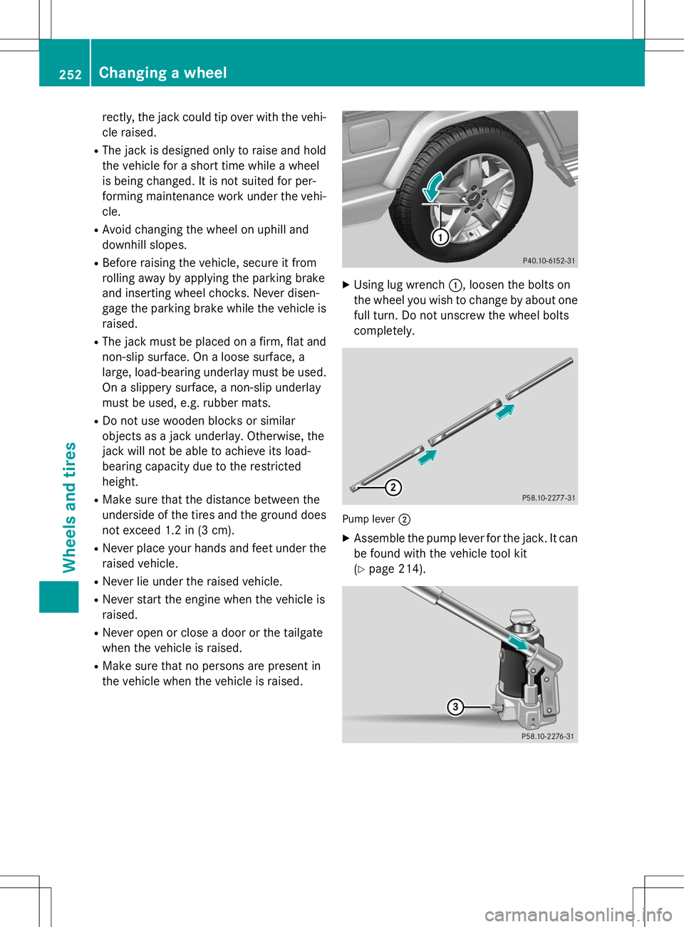
XUsing lug wrench :, loosen the bolts on
the wheel you wish to change by about one full turn. Do not unscrew the wheel bolts
completely.
Pump lever ;
X
Assemble the pump lever for the jack. It can
be found with the vehicle tool kit ( Y page 214).
252Changing a wheel
Wheels and tires
Page 255 of 274

XTurn pressure release screw =clockwise
as far as it will go using notch ;on the
pump lever.
Pressure release screw =is closed.
iDo not turn pressure release screw =by
more than one to two revolutions. Other-
wise, hydraulic fluid could escape.
X Set jack :on solid ground.
X Position jack :on the axle carrier tube ;
of the front or rear axle. Jack :must
always stand vertically, even on slopes.
Make sure that jack :is correctly posi-
tioned under axle carrier tube ;. The front
or rear axle must sit securely in the recess of jack :.
X Raise the vehicle by pumping in the direc-
tion of the arrow until the tire is 1.2 in
(3 cm) off the ground at the most.
Removing a wheel
!Do not place wheel bolts in sand or on a
dirty surface. The bolt and wheel hub
threads could otherwise be damaged when you screw them in.
X Unscrew the wheel bolts.
X Remove the wheel.
Mounting a new wheel
GWARNING
Oiled or greased wheel bolts/wheel nuts and
damaged wheel bolt/wheel nut/wheel hub
threads can cause wheel bolts/wheel nuts to come loose. As a result, you could lose a
wheel while driving. There is a risk of an acci- dent.
Never oil or grease wheel bolts/wheel nuts. In the event of damage to the threads, contact a
qualified specialist workshop immediately.
Have the damaged wheel bolts/wheel nuts or hub threads replaced/renewed. Do not con-
tinue driving.
GWARNING
If you tighten the wheel bolts or wheel nuts
when the vehicle is raised, the jack could tip
over. There is a risk of injury.
Only tighten the wheel bolts or wheel nuts
when the vehicle is on the ground.
!To prevent damage to the paintwork, hold
the wheel securely against the wheel hub
while screwing in the first wheel bolt.
Always pay attention to the instructions and
safety notes in the "Changing a wheel" sec-
tion ( Ypage 250).
X Clean the wheel and wheel hub contactsurfaces.
X Place the new wheel on the wheel hub and
push it on.
X Tighten the wheel bolts until they are fin-
ger-tight.
Lowering the vehicle
GWARNING
The wheels could work loose if the wheel nuts
and bolts are not tightened to the specified
tightening torque. There is a risk of accident.
Have the tightening torque immediately
checked at a qualified specialist workshop
after a wheel is changed.
Changing a wheel253
Wheels and tires
Z
Page 256 of 274

XOpen the pressure release screw on the
jack using the pump lever ( Ypage 251) by
approximately one turn.
X Lower the vehicle until it is once again
standing firmly on the ground.
X Place the jack to one side.
X Tighten the wheel bolts evenly in a cross-
wise pattern in the sequence indicated ( :
to A ). The specified tightening torque is
96 lb-ft (130 Nm).
X Disassemble the pump lever.
X Push the jack piston back in and close the
drain plug.
X Use the bolts to secure the faulty wheel to
the spare wheel bracket ( Ypage 215).
X Stow the jack and the vehicle tools in the
vehicle again.
X Check the tire pressure of the newly instal-
led wheel and adjust it if necessary.
A table with the tire pressures for your vehi-
cle can be found on the B-pillar on the driv-
er's side.
Wheel and tire combinations
General notes
GWARNING
If wheels and tires of the wrong size are used, the wheel brakes or suspension components
may be damaged. There is a risk of an acci-dent.
Always replace wheels and tires with those
that fulfill the specifications of the originalpart.
When replacing wheels, make sure to use the correct:
R designation
R model
When replacing tires, make sure to use the
correct:
R designation
R manufacturer
R model
GWarning
A flat tire severely impairs the driving, steer-
ing and braking characteristics of the vehicle.
There is a risk of an accident.
do not drive with a flat tire. Immediately
replace the flat tire with your spare wheel, or
consult a qualified specialist workshop.
!For safety reasons, Mercedes-Benz rec-
ommends that you only use tires, wheels
and accessories which have been approved by Mercedes-Benz specifically for your
vehicle. These tires have been specially
adapted for use with the driving safety sys-
tems, such as ABS or ESP ®
.
Only use tires, wheels or accessories tes-
ted and approved by Mercedes-Benz. Cer-
tain characteristics, e.g. handling, vehicle
noise emissions or fuel consumption, may
otherwise be adversely affected. In addi-
tion, when driving with a load, tire dimen-
sion variations could cause the tires to
come into contact with the bodywork and
axle components. This could result in dam-
age to the tires or the vehicle.
Mercedes-Benz accepts no liability for
damage resulting from the use of tires,
wheels or accessories other than those tes- ted and approved.
Further information about wheels, tires and
approved combinations can be obtained
254Wheel and tire combinations
Wheels and tires