Page 81 of 100

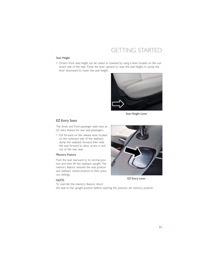
MAINTENANCE PROCEDURES
For information on the maintenance procedures for your vehicle, please refer to “Mainte-
nance Procedures” in “Maintaining Your Vehicle” in your Owner’s Manual or applicable
supplement on the DVD for further details.
MAINTENANCE SCHEDULE
Once A Month Or Before A Trip:
Check windshield washer fluid level
Check the tire inflation pressures and look for unusual wear or damage
Check the fluid levels of the coolant reservoirs and brake master cylinder
Check function of all interior and exterior lights
Required Maintenance Intervals.
Refer to the maintenance schedules on the following page for the required maintenance
intervals.
At Every Service Interval:
Rotate the tires.Rotate at the first sign of irregular wear.The front and rear wheels
are different sizes and cannot be used in place of each other, refer to “Tire Rotation
Recommendations” for further information.
Inspect brake pads, shoes, rotors, drums, and hoses.
Inspect battery cooling system protection and hoses.
Check and adjust hand brake.
MAINTAINING YOUR VEHICLE
79
Page 82 of 100
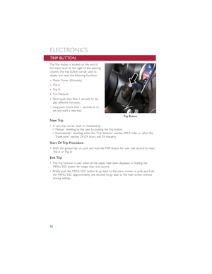
Maintenance ChartRefer to the Maintenance Schedules on the following pages for the required maintenance intervals
.
Mileage or time passed (whichever comes
first)
20,000
30,000
40,000
50,000
60,000
70,000
80,000
90,000
100,000
110,000
120,000
130,000
140,000
150,000
Or Years: 2 3 4 5 6 7 8 9 10 11 12 13 14 15
Or Kilometers:
32,000
48,000
64,000
80,000
96,000
112,000
128,000
144,000
160,000
176,000
192,000
208,000
224,000
240,000
Additional InspectionsInspect the CV joints
.
XX X X X
Inspect front suspension, tie rod ends andboot seals, and replace if necessary
.
XXX X X X X
Inspect the brake linings, parking brake func-tion
.
XXX X X X X
Additional MaintenanceReplace cabin air filter
.
XXX X X X X
Clean and lube sun roof tracks
.
XXX X X X X
Flush and replace the Power Electronics andBattery Thermal Loop Systems at 10 yearsor 150,000 miles (240,000 km) whichevercomes first
.
XX
MAINTAINING YOUR VEHICLE
80
Page 83 of 100
WARNING!
•You can be badly injured working on or around an electric motor vehicle
.Do only service work for which you have the knowledge
and the right equipment
.If you have any doubt about your ability to perform a service job, take your vehicle to a competent me-
chanic
.
•Failure to properly inspect and maintain your vehicle could result in a component malfunction and effect vehicle handling and perfor-mance
.This could cause an accident
.
MAINTAINING YOUR VEHICLE
81
Page 84 of 100
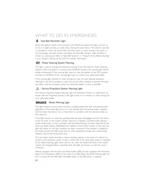
Maintenance Record
Odometer Date Signature, Authorized
Service Center
20,000 Miles(32,000 km) or2 Years30,000 Miles(48,000 km) or3 Years40,000 Miles(64,000 km) or4 Years50,000 Miles(80,000 km) or5 Years60,000 Miles(96,000 km) or6 Years70,000 Miles(112,000 km) or7 Years80,000 Miles(128,000 km) or8 Years
Odometer Date Signature, Authorized
Service Center
90,000 Miles(144,000 km) or9 Years100,000 Miles(160,000 km) or10 Years110,000 Miles(176,000 km) or11 Years120,000 Miles(192,000 km) or12 Years130,000 Miles(208,000 km) or13 Years140,000 Miles(224,000 km) or14 Years150,000 Miles(240,000 km) or15 Years
MAINTAINING YOUR VEHICLE
82
Page 85 of 100
 and is located on the
drivers side under the instrument panel.
CavityVehicle FuseNumberMini Fuse Description
1 F1")
FUSES
Interior Fuses
The interior fuse panel is part of the Body Control Module (BCM) and is located on the
driver's side under the instrument panel.
CavityVehicle FuseNumberMini Fuse Description
1 F12 7.5 Amp Brown Right Low Beam
2 F32 5 Amp TanFront and Rear Ceiling Lights Trunk and DoorCourtesy Lights
3 F53 5 Amp Tan Instrument Panel Node
4 F38 20 Amp Yellow Central Door Locking
5 F36 10 Amp RedDiagnostic Socket, Car Radio, Climate ControlSystem, Tire Pressure Monitor, TCU and CTM
6 F43 20 Amp Yellow Bi-Directional Washer
7 F48 20 Amp Yellow Passenger Power Window
8 F13 7.5 Amp Brown Left Low Beam
9 F50 7.5 Amp Brown Airbag
10 F51 5 Amp TanCar Radio Switch, Climate Control System,Stop Light, Exterior Mirrors, Sunroof Switch,GPS (option) and CTM
11 F37 5 Amp Tan Stop Light Switch, Instrument Panel Node
12 F49 5 Amp TanExterior Mirror, GPS, Electric Mirror, ParkingSensor, Sunroof Switch
13 F31 5 Amp Tan Ignition, Climate Control, RDU and EVCU
14 F47 20 Amp Yellow Driver Power Window
The fuse for the heated mirrors is located behind an access panel on the front of the
Instrument Panel.
NOTE:
This fuse is a single fuse attached directly to the wire harness.
Cavity Mini Fuse Description
F90 5 Amp Tan Heated Mirrors
MAINTAINING YOUR VEHICLE
83
Page 86 of 100

Power Distribution Center #1
The Power Distribution Center #1 is located on the right side of the underhood com-
partment.To access the fuses, remove locking screw and slide cover off.
The ID number of the electrical component corresponding to each fuse can be found on
the back of the cover.
Cavity Maxi Fuse Mini Fuse Description
F01 60 Amp Blue – Body Control Module (BCM)
F02 20 Amp Yellow – HiFi Amplifier
F03 20 Amp Yellow – Ignition Switch
F04 40 Amp Orange – Brake System Module Pump
F05 70 Amp Tan – Electric Power Steering (EPS)
F06 60 Amp Blue – Radiator Fan
F07 40 Amp Orange – Regen Brake Module
F08 40 Amp Orange – HVAC
F09 – 5 Amp TanAir Electric HeaterCharge Indicator
F10 – 10 Amp Red Horn
F11 – 10 Amp RedElectronic Vehicle Control Unit(EVCU)
F14 – 5 Amp Tan High Beam (Shutter)
F15 – 15 Amp Blue Cigar Lighter
F16 – 10 Amp RedHumidity SensorVPAMAC Compressor
F18 – 5 Amp TanElectronic Vehicle Control Unit(EVCU)
F19 – 10 Amp Red HVAC
F20 – 15 Amp Blue Heated Seats – If Equipped
F23 – 25 Amp Clear Anti-Lock Brake Valves
F24 – 7.5 Amp BrownEPSYAW Sensor
F30 – 15 Amp Blue Fog Lamps
F81 30 Amp Green – Electronic Shifter (ESM)
F82 30 Amp Green – Sunroof
F84 – 25 Amp Clear Regen Brake Module
F85 30 Amp Green – Rear Window Heater
F87 – 5 Amp Tan Electronic Shifter (ESM)
MAINTAINING YOUR VEHICLE
84
Page 87 of 100
 #2
The Power Distribution Center #2 is located next to the battery in the underhood com-
partment.To access the fuses, pull the release tabs and remove the cover.
Cavit")
Power Distribution Center (PDC) #2
The Power Distribution Center #2 is located next to the battery in the underhood com-
partment.To access the fuses, pull the release tabs and remove the cover.
Cavity Maxi Fuse Mini Fuse Description
FPT9 – 15 Amp Blue Battery Pack Control Module (BPCM)Power Inverter Module (PIM)
FPT13 – 10 Amp Red EAC (AC Compressor)On Board Charging Module (OBCM)
FPT16 – 5 Amp Tan Intelligent Battery Sensor (IBS)
FPT17 – 10 Amp Red EAC (AC Compressor)Radiator Fan
FPT20 – 10 Amp Red Electronic Vehicle Control Unit (EVCU)
Cavity Cartridge Fuse Description
FPT3 25 Amp White Battery Coolant Pump
FPT5 20 Amp Lt.Blue Inverter Coolant Pump
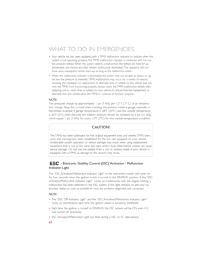
TIRE PRESSURES
•Check the inflation pressure of each tire, including the spare tire, at least monthly and
inflate to the recommended pressure for your vehicle.
•The tire pressures recommended for your vehicle are found on the “Tire and Loading
Information” label located on the driver’s side door opening.
NOTE:
Refer to the Owner's Manual on the DVD
for more information regarding tire warn-
ings and instructions.
Tire And Loading Information Label
MAINTAINING YOUR VEHICLE
85
Page 88 of 100

WARNING!
•Overloading of your tires is dangerous.Overloading can cause tire failure, affect
vehicle handling, and increase your stopping distance.Use tires of the recom-
mended load capacity for your vehicle.Never overload them.
•Improperly inflated tires are dangerous and can cause collisions.Under-inflation is
the leading cause of tire failure and may result in severe cracking, component sepa-
ration, or “blow out”.Over-inflation reduces a tire’s ability to cushion shock.Ob-
jects on the road and chuck holes can cause damage that results in tire failure.
Unequal tire pressures can cause steering problems.You could lose control of your
vehicle.Over-inflated or under-inflated tires can affect vehicle handling and can fail
suddenly, resulting in loss of vehicle control.
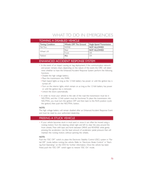
TIRE ROTATION RECOMMENDATIONS
NOTE:
The front and rear wheels are different sizes and cannot be used in place of each other.
Rotate the wheels “side-to-side” as shown in the diagram.
The tires on the front and rear of your
vehicle operate at different loads and per-
form different steering, driving, and braking
functions.For these reasons, they wear at
unequal rates.
These effects can be reduced by timely
rotation of tires.The benefits of rotation
are especially worthwhile with aggressive
tread designs such as those on all season
type tires.Rotation will increase tread life, help to maintain mud, snow and wet traction
levels, and contribute to a smooth, quiet ride.
Refer to the “Maintenance Schedule” for the proper maintenance intervals.The reasons
for any rapid or unusual wear should be corrected prior to rotation being performed.
MAINTAINING YOUR VEHICLE
86


20,000
30,000
40,000
50,000
60,000
70")

 or2 Years30,000 Miles(48,000 km) or3 Years40,000 Miles(64,000 km) or4 Years50,000 Miles(80,000 km) or5 Yea")