Page 17 of 100

•If the self test is successful the AC LED, the Fault Indicator LED and the four Charge
Level LED's will turn solid green.
•The EVSE LED's will be used to indicate the vehicle's connection status if no faults are
found during the self test.
AC LEDFault Indicator
LEDCharge Level Indicator LED's
•• ••••
•After the EVSE is connected to the vehicle's charge inlet the EVSE will continue to
illuminate all LED's green.
•Once the vehicle begins charging the EVSE Charge level LED's will illuminate in order
from left to right, then shut off.This pattern will repeat as long as the EVSE remains
connected to AC power and the battery is charging.
•The LED's are illuminated and turn off at the rate of one change per second.
AC LEDFault Indicator
LEDCharge Level Indicator LED's Time
•• •ooo1.0 sec
•• ••oo2.0 sec
•• •••o3.0 sec
•• ••••4.0 sec
NOTE:
Refer to the Level 1 User Manual for any additional information on its use or operation.
CAUTION!
Do not bend or damage the Level 1 EVSE terminals as this could cause the EVSE to
become inoperative and/or illuminate the fault LED.
GETTING STARTED
15
Page 18 of 100

CHARGING THE HIGH VOLTAGE BATTERY
1.Put the vehicle in PARK.
2.Turn the ignition to the OFF position.
3.Remove the Level 1 EVSE from its storage bin by lifting the rear cargo cover.
4.Uncoil the entire length of the EVSE
(charge cord).
5.Plug the EVSE into a standard 120V AC
outlet that is properly grounded.It is
recommended that the EVSE is con-
nected to an AC outlet on a circuit
which is not electrically loaded by other
devices.Extension cords may not be
used.
NOTE:
All of the EVSE LED’s illuminate green.
6.Open the charge receptacle door.
NOTE:
The charge receptacle door is locked
whenever the vehicle is locked.Unlock the doors to unlock the charge receptacle door
for charging.
7.Plug the EVSE into the charge receptacle.Push the EVSE in firmly until it is completely
engaged (if not completely engaged the vehicle may not charge).
NOTE:
•The vehicle will initiate the charging
cycle automatically when all the condi-
tions are satisfied.
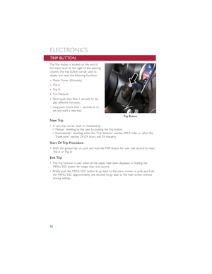
Electric Vehicle Supply Equipment (EVSE)
Charge Receptacle
GETTING STARTED
16
Page 19 of 100

•The vehicle battery gauge will show the pattern for charging.
•Do not use an extension cord with
the EVSE.
•To remove the EVSE push the button
on the connector and pull firmly to
remove it from the vehicle’s charge
receptacle.
8.Close the charge receptacle door.
NOTE:
•In the event of an error in the charging
process the AC power to the vehicle will
stop and a red indicator will illuminate
on the EVSE.
•Keep the door for the charge receptacle
closed when not in use.
Instrument Panel State Of Charge Indicator
•In addition to the instrument cluster the vehicle is also equipped with a State Of
Charge indicator.The indicator is made up of five lights that are mounted to the cen-
ter of the instrument panel.
•The State Of Charge indicator repre-
sents the current state of charge for the
high voltage battery.The indicator lights
quickly identify the battery state of
charge while the vehicle is being
charged.Each light represents an incre-
mental 20% level of charge.Solid and
blinking lights indicate charge status simi-
lar to a mobile device.
NOTE:
In the event of an error in the charging
process the outer two lights will blink.
Number Of Indicator Lights Illuminated Percent Of Battery Charge
1 Light 0 – 20%
2 Lights 21 – 40%
3 Lights 41 – 60%
4 Lights 61 – 80%
5 Lights 81 – 100%
Battery Gauge
State Of Charge Indicator
GETTING STARTED
17
Page 20 of 100

STARTING YOUR 500e
•Before starting your vehicle, adjust your seat, adjust both inside and outside mirrors,
and fasten your seat belts.
WARNING!
•Never leave children alone in a vehicle, or with access to an unlocked vehicle.
•Allowing children to be in a vehicle unattended is dangerous for a number of rea-
sons.A child or others could be seriously or fatally injured.Children should be
warned not to touch the parking brake, brake pedal or the shift buttons.
•Do not leave the key fob in or near the vehicle (or in a location accessible to chil-
dren).A child could operate power windows, other controls, or move the vehicle.
NOTE:
Make sure the EVSE is not plugged into the vehicle.
•Turn the key to the START position while your vehicle is in PARK.When the ignition
key is turned to the START and then the RUN position, the “READY” indicator in the
Electronic Vehicle Information Center (EVIC) will illuminate to indicate the 500e's Elec-
tric Drive System has started.
•When the “READY” indicator is illuminated, your 500e is ready to be driven.
•If the “READY” indicator fails to illumi-
nate after you have followed the normal
starting procedure, contact your autho-
rized dealer.
NOTE:
You must push the brake pedal before
shifting out of PARK.
Ready Light
GETTING STARTED
18
Page 21 of 100
 transmitter once to
lock all the doors and the liftgate.
•Push the UNLOCK button on the")
KEY FOB
Locking And Unlocking The Doors
And Liftgate
•Push the LOCK button on the Remote
Keyless Entry (RKE) transmitter once to
lock all the doors and the liftgate.
•Push the UNLOCK button on the Re-
mote Keyless Entry (RKE) transmitter
once to unlock the driver’s door only
and twice within five seconds to unlock
all the doors and liftgate.
All doors can be programmed to unlock on
the first push of the UNLOCK button.
Refer to “Programmable Features” in this
guide.
Opening The Liftgate
•To open the liftgate, push the LIFTGATE
release handle located on the underside
of the license plate bar and pull the lift-
gate open with one fluid motion.
•Push the LIFGATE button located on the
key fob.
WARNING!
Never leave children alone in a vehicle, or with access to an unlocked vehicle.Allowing
children to be in a vehicle unattended is dangerous for a number of reasons.A child or
others could be severely injured or killed.Children should be warned not to touch the
parking brake, brake pedal, or the transmission gear selector.Do not leave the Key Fob
in the vehicle, or in a location accessible to children.A child could operate power win-
dows, other controls, or move the vehicle.
Key Fob
1 — Unlock Doors/Open Power Top — IfEquipped2 — Key Release3 — Lock Doors4 — Liftgate
GETTING STARTED
19
Page 22 of 100

VEHICLE SECURITY ALARM
The Vehicle Security Alarm monitors the vehicle doors for unauthorized entry and the
Keyless Enter-N-Go™ START/STOP button for unauthorized operation.While the Vehicle
Security Alarm is armed, interior switches for door locks and decklid release are disabled.
If something triggers the alarm, the Vehicle Security Alarm will provide the following au-
dible and visible signals: the horn will pulse, the park lamps and/or turn signals will flash,
and the Vehicle Security Light in the instrument cluster will flash.
To Arm:
Push the Key Fob LOCK button.
To Disarm The System:
Push the Key Fob UNLOCK button or cycle the ignition to the ON/RUN position.
The Vehicle Security Alarm is designed to protect your vehicle.However, you can create
conditions where the Vehicle Security Alarm will give you a false alarm.If one of the pre-
viously described arming sequences has occurred, the Vehicle Security Alarm will arm re-
gardless of whether you are in the vehicle or not.If you remain in the vehicle and open
a door, the alarm will sound.If this occurs, disarm the Vehicle Security Alarm.
If the Vehicle Security Alarm is armed and the battery becomes disconnected, the Vehicle
Security Alarm will remain armed when the battery is reconnected.The exterior lights
will flash, and the horn will sound.If this occurs, disarm the Vehicle Security Alarm.
POWER DOOR LOCKS
The vehicles power door locks are activated by moving the inside door handles.
Push or pull the driver’s door handle to lock or unlock the doors and liftgate when the
doors are closed.
SEAT BELT SYSTEMS
Lap/Shoulder Belts
•All seating positions in your vehicle are equipped with lap/shoulder belts.
•Be sure everyone in your vehicle is in a seat and using a seat belt properly.
•Position the lap belt so that it is snug and lies low across your hips, below your abdo-
men.To remove slack in the lap belt portion, pull up on the shoulder belt.To loosen
the lap belt if it is too tight, tilt the latch plate and pull on the lap belt.A snug seat belt
reduces the risk of sliding under the seat belt in a collision.
•Position the shoulder belt across the shoulder and chest with minimal, if any slack so
that it is comfortable and not resting on your neck.The retractor will withdraw any
slack in the shoulder belt.
GETTING STARTED
20
Page 23 of 100

Seat Belt Pretensioner
•The front seat belt system is equipped with pretensioning devices that are designed to
remove slack from the seat belt in the event of a collision.
•A deployed pretensioner or a deployed air bag must be replaced immediately.
WARNING!
•In a collision, you and your passengers can suffer much greater injuries if you are
not properly buckled up.You can strike the interior of your vehicle or other pas-
sengers, or you can be thrown out of the vehicle.Always be sure you and others
in your vehicle are buckled up properly.
•A shoulder belt placed behind you will not protect you from injury during a colli-
sion.You are more likely to hit your head in a collision if you do not wear your
shoulder belt.The lap and shoulder belt are meant to be used together.
•A seat belt that is too loose will not protect you properly.In a sudden stop, you
could move too far forward, increasing the possibility of injury.Wear your seat belt
snugly.
•A frayed or torn seat belt could rip apart in a collision and leave you with no pro-
tection.Inspect the seat belt system periodically, checking for cuts, frays, or loose
parts.Damaged parts must be replaced immediately.Do not disassemble or
modify the system.Seat belt assemblies must be replaced after a collision.
SUPPLEMENTAL RESTRAINT SYSTEM (SRS) — AIR BAGS
Air Bag System Components
Your vehicle may be equipped with the following air bag system components:
•Occupant Restraint Controller (ORC)
•Air Bag Warning Light
•Steering Wheel and Column
•Instrument Panel
•Knee Impact Bolsters
•Advanced Front Air Bags
•Supplemental Side Air Bags
•Supplemental Knee Air Bags
•Front and Side Impact Sensors
•Seat Belt Pretenioners
•Seat Belt Buckle Switch
•Seat Track Position Sensors
GETTING STARTED
21
Page 24 of 100

Advanced Front Air Bags
•This vehicle has Advanced Front Air Bags for both the driver and front passenger as a
supplement to the seat belt restraint systems.The Advanced Front Air Bags will not
deploy in every type of collision.
•Advanced Front Air Bags are designed to provide additional protection by supplement-
ing the seat belts.Advanced Front Air Bags are not expected to reduce the risk of
injury in rear, side, or rollover collisions.
•The Advanced Front Air Bags will not deploy in all frontal collisions, including some that
may produce substantial vehicle damage — for example, some pole collisions, truck
underrides, and angle offset collisions.
•On the other hand, depending on the type and location of impact, Advanced Front Air
Bags may deploy in crashes with little vehicle front-end damage but that produce a
severe initial deceleration.
•Because air bag sensors measure vehicle deceleration over time, vehicle speed and
damage by themselves are not good indicators of whether or not an air bag should
have deployed.
•Seat belts are necessary for your protection in all collisions, and also are needed to
help keep you in position, away from an inflating air bag.
•The air bags must be ready to inflate for your protection in a collision.The Occupant
Restraint Controller (ORC) monitors the internal circuits and interconnecting wiring
associated with air bag system electrical components.
•The ORC turns on the Air Bag Warning Light in the instrument panel for approxi-
mately four to eight seconds for a self-check when the ignition switch is first turned to
the ON/RUN position.After the self-check, the Air Bag Warning Light will turn off.
If the ORC detects a malfunction in any part of the system, it turns on the Air Bag
Warning Light, either momentarily or continuously.A single chime will sound to alert
you if the light comes on again after initial startup.
•The ORC monitors the readiness of the electronic parts of the air bag system when-
ever the ignition switch is in the START or ON/RUN position.If the ignition switch is
in the OFF position or in the ACC position, the air bag system is not on and the air
bags will not inflate.
•If the Air Bag Warning Light in the instrument panel is not on during the four to eight
seconds when the ignition switch is first turned to the ON/RUN position, stays on, or
turns on while driving, have the vehicle serviced by an authorized service center imme-
diately.
NOTE:
If the speedometer, tachometer, or any engine related gauges are not working, the Occu-
pant Restraint Controller (ORC) may also be disabled.In this condition the air bags may
not be ready to inflate for your protection.Have an authorized dealer service the air bag
system immediately.
GETTING STARTED
22