Page 25 of 268

M N
ci LL co
rl I.O
"' N
"' rl
Driver information
system
Introduction
The Driver information display inside the instru
ment cluster provides you, the driver, with im
portant information.
Fig. 7 Instrument cluster: ce nter display
Fig . 8 Wipe r lever: controls fo r the men u display
Cent er dis play
With the ignition on, the display in the Driver In
formation System shows the following informa
tion :
- CD* inserted or Radio * station set
- Outs ide temperature* : At temperatures below
41 °f (+S
0
(), a snowf lake symbol appears in
front of the temperature display¢&. .
- Wa rning if one of the doors, front lid o r engine
compartment lid is not closed.
Additional function s
You can open the following functions in the Driv
er Information System display by pressing the
I RESET I button ¢ fig. 8 one or more times:
Digital speedometer*
T ire pressure monitoring*
¢page226
Dr iver inform atio n sy stem
Trip computer Q page24
Efficiency program* ¢page26
Service interval display Qpage27
Speed warning ¢page 79
Gearshift selector positions Au -i=>page83
tomatic transmission
Adaptive cr uise control*
¢ page 90
Auto Chec k Control
Some functions and vehicle components are
scanned for their operating status when yo u
switch the ignition on and whi le you are driving.
Malfunctions or required service procedures are
signaled audibly and indicated by red and yellow
illuminated symbols and reminders in the dis
play.
A WARNING
--- Never rely exclusively on the outside tem pe ratu re d isplay to dete rm ine if a road sur
face is icy or not. Keep in mind that road sur
faces, espe cially bridges and overpasses,
could be ice covered and slippery even at an
outside temperature above 41 °f (+S °C).
- Always remember, even if the "snowflake"
symbo l (ice warning) does not appear in the
display, black ice cou ld be on the road .
-Always red uce your speed and d rive with
specia l care in cold weather conditions when
the chance of encountering icy road surfaces
increases.
(j) Tips
If the vehicle is stationary, or if yo u are driv
ing at a very low speed, the temperature
shown in the disp lay might be slightly higher
than the actual outside temperature . This is
caused by the heat being radiated from the
engine.
23
Page 26 of 268

Driver information system
Trip computer
Introduction
The trip computer gives you information on cur
rent and average fuel mileage , average speed ,
fuel range and driving time .
Fig. 9 Trip computer d isplay: Ave rage fuel m ileage
~ 9 a: CX) m
The fo llow ing information is contin uously evalu
ated by the trip computer and can be d isplayed
sequent ia lly in the instrument cluster display:
Fuel range
The estima ted c ruising range i n miles (km) ap
pea rs in the disp lay . This te lls you how fa r your
ve hicle w ill be able to trave l on t he current ta nk
of fuel and with the same driv ing style. The d is
p lay changes in increments of 5 miles (10 km) .
The cruising range is calcu lated based on t he f ue l
consumption for the last 18 m iles (30 km). If yo u
drive conse rvative ly, the cruising range will in
crease.
Average fuel mileage
The average fuel e co nomy in MPG (l/ 100 k m)
since yo u last cleared the memory appears in this
d is pl ay. You can use this display to ad just your
driving technique to achieve a desired mileage.
Current fuel mileage
The inst antaneo us f ue l cons umption in miles per
ga llon (l/100 km) is shown in this display. Yo u
can use t his disp lay to adjust your driving techni
que to achieve a des ired mileage .
F ue l cons umption is rec alcul ated at intervals of
33 y ards (30 me ters). Th is disp lay swit ches to
ga llons/hou r (li ters/hour) when the vehicle is not
mov ing.
24
Average speed
The aver age spee d in mph (km/ h) sin ce you last
rese t the memory appears in the display .
Elapsed time
The length of time that yo u have been d riving
s ince you last reset the memory appears in this
display .
Distance
The distance that has been covered since the last
time the memory was cleared appears i n the dis
play .
0) Tips
-Fuel consumptions (average and current),
range and speed a re displayed in me tric
units on Canad ian mode ls .
- All stored val ues will be lost if the vehicle
bat tery is disconnected .
Memories
The trip computer is equipped with two fully au
tomatic memories as well as an efficiency pro
gram* .
Fig. 10 Tri p comput er di sp la y: me mory leve l 1
You can switch between the trip computer 1 and
2 and the efficiency program* by p ressing t he
I RESET I button @<=> page 25, fig. 11 .
You can tell wh ic h memory leve l is currently ac
tive by the number o r the sig n in the display
Q fig. 10. The data from the single-t rip memory
(memo ry leve l 1) is being d isplayed if a
D ap
pears in the display. If a
fJ is shown, t hen the da-
ta from the total-t rip memory is being d isp layed .,,_
Page 27 of 268
 1.11
N 1.11 ,....,
(memory level 2). The fuel pump nozz le iii
indicates the efficiency program*¢ page 26.
Single-t rip memory (Trip computer 1 )
The single")
M N
ci u.. co ,...., \!) 1.1'1
N 1.1'1 ,....,
(memory level 2). The fuel pump nozz le iii
indicates the efficiency program*¢ page 26.
Single-t rip memory (Trip computer 1 )
The single -t rip memo ry s to res the trip informa
tion from the t ime the ig nit ion is tu rned on unt il
it is turned
off. If the t rip is con tinued within 2
hour s
from the time the ignition was turned off,
the new data wi ll be included in the calculation of
the current trip information .
If the trip is inter
rupted for
more than 2 hours the memory is re
set automat ica lly.
Total -trip memo ry (Trip computer 2 )
Unlike the single-trip memory , the tota l-trip
memory is not reset automatically. This permits
you to evaluate your driving data for the entire
period between manual resets.
Efficiency program*
The eff ic iency p rog ram can help you to use less
fuel ¢
page 26.
Operation
The trip computer is controlled by two switches
on the windshield wiper lever .
Fig . 11 W inds hield w ipe r leve r: co ntro ls fo r th e trip co m
p u ter
Operating
"'T o disp lay the t rip compu ter memory leve ls ,
press t he
I RESE T I but ton @¢ fig. 11 repeated
l y until the des ired memo ry level is shown in
t h e display .
"' To disp lay t rip information within a memory
l evel, press the top or bottom part of the func
t ion select io n switch @.
Dri ver information s ystem
The trip computer will not ope rate un less the ig
nition is on. When you turn o n the ignition, the
f unct ion that was in use when yo u last turned the
ignition
off wi ll be displayed.
In add ition to info rmation about the trip comput
er (trip computer 1, 2 and the efficiency pro
gram *), information about othe r systems can al
so be shown in the display. To switch the display betwee n the diffe rent information, tap the
I RESET ! button@ briefly .
Resetting values to zero
"' Select a value in the desired trip compute r or in
the effic iency program *.
"' Press and hold the
I RESE T I button @for at
least one second . All values in the selected trip
computer or in the eff ic iency program* a re re
set to zero .
If the data in tr ip computer 1 are deleted, then
t h e va lues in the eff iciency program* will also be
r eset.
With some vehicle equ ipment levels, the va lues
for the single tr ip or total trip memory can also
be reset i n the Infotai nment system
¢ page 25.
(D Tips
All stored va lues w ill be lost if the veh icle bat
tery is d isconnected .
Basic Settings for the trip computer
Applies to vehicles: with trip computer
The radio or MM!* operating unit is used for set
ting the trip computer 's basic settings.
"' Select: Function button I CAR!> Instrument
cluster > On -board computer 1 or On-board
computer 2 .
The values in the sing le-tr ip or the total-t rip
memory can all be reset to zero at the same t ime
u nder
Reset in the menu.
In addition, yo u can determi ne what info rmation
from t he trip computer sho uld be shown in the
instrument cluster display. If one of the pieces of
driver information is turned
Off , that driver .,.
25
Page 28 of 268

Driver information system
information will not be shown in the display. The
information will continue to be calculated by the
tr ip computer and can be turned back
On at any
time.
(D Tips
- This function is not available on all vehicles.
- The driving information in the efficiency
program is also reset to zero with the sin
gle-trip memory.
Efficiency program
Description
App lies to vehicles: with trip computer with efficiency pro
gram
Fig. 12 Display: efficie nc y program
.. Press the I RESET I button @¢ page 2 5, fig. 11
repeatedly until the efficiency program appears
in the disp lay.
The efficiency program can help you to use less
fue l.
It evaluates driving information in reference
to fuel consumption and shows other equipment
influencing consumption as well as shift recom
mendations. Fuel economy messages
¢
page 26 provide tips for efficient driving.
The eff ic iency program uses distance and con
sumption data from trip computer
l. If the data
are de leted in the efficiency program, those val
ues are also reset in trip computer
l.
26
Other equipment
Applies to vehicles: with trip computer with efficiency pro
gram
Fig. 13 Display: other equipment
.. In the efficiency program, press the function
selection switch ¢
page 2 5, fig. 11 ® repeat
edly until the other equipment appears in the
disp lay .
Other equipment that is currently affecting fuel
consumption is listed in the efficiency program.
The display shows up to three other items of
equipment @. The equipment using the most
fuel is listed first. If more than three items us ing
fuel are switched on, the equipment that is cur
rently using the most fuel is displayed.
A scale @also shows the current total consump
t ion of all other equ ipment .
Fuel economy messages
Applies to vehicles: with trip computer with efficiency pro
gram
Fig. 14 Display: fuel economy message
"'
"' ->l CD m
Fuel economy messages are displayed when fuel
consumption is increased by certa in conditions. If
you follow these fuel economy messages, you can
reduce your vehicle's consumption of fuel. The ..,.
Page 29 of 268
 1.11
N 1.11 ,....,
messages appear automatically and are only dis
p layed in the efficiency program . The fuel econo
my messages turn
off automatically after")
M N
ci u.. co ,...., \!) 1.1'1
N 1.1'1 ,....,
messages appear automatically and are only dis
p layed in the efficiency program . The fuel econo
my messages turn
off automatically after acer
tain period of time.
.. To turn a fuel economy message
off immed iate
l y after it appears, press the I RESET
I b utton
¢ page 25, fig. 11 @ , or
.. Press the function selection switch¢
page 25,
fig. 11
@ .
(D Tips
-Once you have t urned a fuel economy mes
sage
off, i t will only appear aga in after you
turn the ignit ion on again.
- The fuel economy messages are not dis
played in every instance, but rather in inter
vals over a per iod of t ime .
Service interval display
The service interval display reminds you when
your next service is due .
Fig. 1 5 Dis p lay: Service interval d isp lay
~ 0 ci:
"' a,
The sc hed ule for the next oil c hange or inspec
tion is calculated a utomatically and displayed ac
cordingly. The display works in two stages :
Service reminder
30 days before the nex t servi ce is due, a serv ice
reminde r appea rs in the disp lay when you tu rn on
the ignition
¢ fig. 15.
Afte r about 5 seconds the display sw itches back
t o no rma l. The dis tan ce and t ime rem aining are
updated eac h time the ignition is turned on unti l
the date due for service is reached .
Driver information s ystem
Service due
When the d ue date for se rvice is reached, t he
message
Service due! appears in the inst rument
cluster immediate ly afte r yo u turn on the igni
tion . Additiona lly, a warning tone sounds. Afte r
about 5 seconds the display switches back to nor
mal.
Calling up the service schedules
If or when an oi l change or inspection is due, can
be shown in t he radio or
M MI* dis play by select
ing the service interval display in the ca r men u.
Se lect I CAR I funct ion button >
Service interval
display
or ICARI function button > Car systems *
control button > Servicing & checks .
Resett ing the service interval display
Your a uthorized Audi dea ler will reset the corre
sponding service schedule after performing the appropriate service on your vehicle. You also have
the possibility to reset the oil change schedule af
ter having performed an oi l change according to
Audi specifica tions . Select I CAR ! funct ion button
> Service interval display > Res et oil change in
terval
o r! CARlfunction button> Car systems*
control b utton > Servicing & check s > Reset oil
change inter val.
(D Note
- Only re se t the oil change display when yo u
h ave comple ted an o il change.
- If you disconnect the batte ry termina ls, no
c al cul ations can be made for the se rv ice in
t erval disp lay during t his time and n o serv
ice reminder w ill appea r. R emembe r that
observing the p ro p er service interva ls is vi
tally impo rtant to exten ding the life of yo ur
vehicle, part icular ly the eng ine, and main
taining its va lue. Even if the mileage dr iven
is low, the maxim um per iod of one year
from one service to t he nex t must not be ex
ceeded.
(D Tips
The information in the Service Reminder re
mains stored even when th e vehicle battery is
disco nnecte d.
27
Page 30 of 268

Malfunction Indicator Lamp (MIL)
The Malfunction Indicator Lamp (MIL) ¢• in the
instrument cluster is part of the On-Boa")
Driver information system
On Board Diagnostic
System (OBD)
Malfunction Indicator Lamp (MIL)
The Malfunction Indicator Lamp (MIL) ¢• in the
instrument cluster is part of the On-Board Diag
nostic (OBD II) system.
The warning/indicator light i lluminates when the
ignition is switched on and goes out after the en
gine starts and the idle has stabilized. This indi
cates that the MIL is working properly.
If the light does not go out after the engine is
started, or illuminates while you are driving, a malfunction may exist in the engine system. If
the light illuminates, the catalytic converter
could be damaged.
Continue driving
with reduced power (avoiding
sustained high speeds and/or rapid acce lerations)
and have the condition corrected. Contact your
authorized Audi dealer.
I f the light illuminates, the electronic speed lim
iter may also be malfunctioning. For more infor
mation
c::> page 28, Electronic speed limiter.
An improperly closed fuel filler cap may also
cause the MIL light to illuminate
c::> page 192.
On-Board Diagnostics
Fig. 16 Loca tion of Data Link Connec tor (DLC)
On-Board Diagnostics monito rs the components
of your emission control system. Each monitored
component in your engine system has been as
signed a code. In case of a malfunction, the com
ponent will be identified and the fault stored as a
code in the control module memory .
28
The MIL light may also illuminate if there is a
l eak in the on-board fuel vapor recovery system.
If the light illuminates after a refueling, stop the
vehicle and make sure the fuel filler cap is prop
erly closed
c::> page 192.
In order to make an accurate diagnosis, the stor
ed data can only be displayed using spec ia l diag
nostic equipment (generic scan tool for 080).
In order to connect the specia l diagnostic equip
ment, push the plug into the Data Link Connector
(DLC). The DLC is located to the r ight of the hood
release
c::> fig. 16.
Your authorized Audi dealer or qualified work
shop can interpret the code and perform the nec
essary repair.
A WARNING
Do not use the diagnostic connector for per
sonal use. Incorrect usage can cause malfunc
tions, which can increase the risk of a colli
sion!
Electronic speed limiter
Your vehicle may be factory equ ipped with tires
that are rated for a maximum speed of 130 mph
(210 km/h) . This is may be less than the maxi
mum speed of your vehicle. To reduce the risk of
sudden tire failure and loss of control if the vehi
cle is operated at excessive speeds, your vehicle
has an e lectronic speed limiter. The electronic
speed limiter prevents your vehicle from going
faster than the tire speed rating. For more infor
mation
c::> page 209.
-
If the engine contro l unit receives faulty vehicle
roadspeed signals, the Malfunction Indicator
Light (MIL)
II will illuminate. If this occurs, con
tact the nearest author ized Audi dealer for assis
tance.
A WARNING
Always observe the posted speed lim its and
adjust your speed to suit prevailing road, traf
fic and weather conditions. Never drive your
vehicle faster than the maximum speed rating
of the tires installed.
-
Page 31 of 268
 1.11
N 1.11 ,....,
Opening and closing
Central locking
General description
The power locking system locks or unlocks all
doors and the rear lid simultane")
M N
ci u.. co ,...., \!) 1.1'1
N 1.1'1 ,....,
Opening and closing
Central locking
General description
The power locking system locks or unlocks all
doors and the rear lid simultaneously.
You can lock and unlock the vehicle centrally. You
have the following choices:
- Remote master key
c:::> page 32,
-Door handles with convenience key*
c:::> page 32,
-Lock cylinder at the dr iver's door c:::> page 34,
or
- Power locking switch inside
c:::> page 33.
Au tomatic locking
The automat ic locking feature locks all the veh i
cle doors and the rear l id when you drive faster
than 9 mph ( 15 km/h).
The car is unlocked again once the ignition key is
removed . In add ition, the vehicle can be unlocked
if the opening function in the power locking sys
tem sw itch or at one of the door levers is actuat
ed. The Auto Lock function can be turned on and
off in the rad io or MMI*
c:::> page 34.
Additionally, in the event of a crash with a irbag
deployment the doors are automatically un locked to allow access to the vehicle .
Selective unlo cking
When you lock the vehicle, the power locking sys
tem w ill lock the doors and the rear lid. When un
lock ing, you can set in the radio or MMI* whether
only the drive r's door o r the ent ire vehicle should
be un locked
c:::> page 34.
Anti- theft alarm w arning sy stem
If the anti-theft alarm warning system detects a
break-in into the vehicle, acoustic and v isual
warn ing s ignals are tr iggered .
The anti-theft warning system is activated auto
mat ically when you lock the vehicle. It is deact i
vated when unlocking using the remote key, w ith
the mechanical key, and when you switch on the
i gnit ion.
Op ening and cl osing
The alarm also turns off when the a larm cycle has
expired.
Turn signals
When you unlock the veh icle, the turn s ignals
flash twice, when you lock it once. If they do not
flash , one of the doors, the luggage compart
ment lid or the hood is not locked or the ignition
is still switched on.
Unint entionally l ocking your self out
In the follow ing cases there safeguards to pre
vent you locking your remote master key in the
vehicle:
- The vehicle does not lock w ith the power lock
ing sw itch
c:::> page 33 if the driver's door is
open.
- On veh icles with co nvenience key*, if the most
recently used master key is in the luggage com
par tment, the rear lid is automatically unlocked
again after it is closed .
Do not lock your veh icle w ith the remote master
key or co nvenience key* unt il all doors and the
rear lid are closed. In this way you avoid locking
yourself out accidentally .
A WARNING ,-c=-
-When you leave the vehicle, always remove
the ignition key and take it with you. This
will prevent passengers (children, for exam
ple) from accidentally being locked in the
veh icle should they accidentally press the
power locking sw itch in the front doors .
- Do not leave children inside the vehicle un
supervised . In an emergency it would be im
possible to open the doors from the outs ide
without the key.
(D Tips
- In the event of a crash with airbag deploy
ment all locked doors w ill be automatically
unlocked to give access to the veh icle occu
pants from the outside.
- If the power locking system should mal
function, you can lock the driver's door us ing the mecha nical key
c:::> page 34.
29
Page 32 of 268

Opening and closing
-If the power locking system should fail, you
can still open the fuel tank flap in an emer
gency ~
page 194.
-You are well advised not to keep valuables
inside an unattended vehicle, visible or not.
Even a properly locked vehicle cannot pro
vide the security of a safe.
- If the LED in the upper edge of the driver's
door panel comes on for about 30 seconds
after the vehicle is locked, there is a mal
function in the power locking or the anti
theft warning system. Have the malfunction
corrected by an authorized Audi dealership
or qualified repair facility.
Key set
Fig . 17 Key set
m 0 ±
~
@ Remote control key with mechanical key
You can centrally lock and unlock your vehicle and
start the engine with the master key with remote
control. A mechanical key is integrated in the
master key
~page 31 .
@ Emergency key
The emergency key is not intended for constant
use . It should only be used in an emergency, for
example, in place of the ignition key
~ page 7 4 . Keep it in a safe place and do not
carry it on your key ring.
Key replacement
If you lose a key, contact your authorized Audi
dealer immediately to have the
lost key disabled.
Be sure to bring all your keys with you .
30
Number of keys
You can check the number of assigned keys to
your vehicle
¢ page 11. This allows you to make
sure you have received all of the keys when you purchase a used vehicle.
Data in the master key
During driving, service and maintenance-relevant
data is continuously stored on your master key .
Your Audi service adviser can read out this data
and tell you about the work your vehicle needs.
This applies also to vehicles with convenience
key*.
Personal comfort settings
If two people use one vehicle, it is recommended
that each person always uses "their own" master key. When the ignition is turned off or when the
vehicle is locked, personal convenience settings
for the following systems are stored and as
signed to the remote master key.
- Climate control
- Power locking system
- Seat memory*
- Parking system*
- Adaptive cruise control* - Side assist*
- Drive select*
The stored settings are automatically recalled
when you unlock the vehicle, when you open the
doors or when you turn on the ignition.
A WARNING
-Do not leave your vehicle unattended with
the key in the ignition lock. Entry by unau
thorized persons could endanger you or re
sult in theft or damage the vehicle.
- Do not leave children unattended in the ve
hicle, especially with access to vehicle keys.
Unguarded access to the keys provides chil
dren the opportunity to start the engine
and/or activate vehicle systems such as the
power windows etc. Unsupervised operation
of any vehicle system by children can result
in serious injury.
.
 1
1 2
2 3
3 4
4 5
5 6
6 7
7 8
8 9
9 10
10 11
11 12
12 13
13 14
14 15
15 16
16 17
17 18
18 19
19 20
20 21
21 22
22 23
23 24
24 25
25 26
26 27
27 28
28 29
29 30
30 31
31 32
32 33
33 34
34 35
35 36
36 37
37 38
38 39
39 40
40 41
41 42
42 43
43 44
44 45
45 46
46 47
47 48
48 49
49 50
50 51
51 52
52 53
53 54
54 55
55 56
56 57
57 58
58 59
59 60
60 61
61 62
62 63
63 64
64 65
65 66
66 67
67 68
68 69
69 70
70 71
71 72
72 73
73 74
74 75
75 76
76 77
77 78
78 79
79 80
80 81
81 82
82 83
83 84
84 85
85 86
86 87
87 88
88 89
89 90
90 91
91 92
92 93
93 94
94 95
95 96
96 97
97 98
98 99
99 100
100 101
101 102
102 103
103 104
104 105
105 106
106 107
107 108
108 109
109 110
110 111
111 112
112 113
113 114
114 115
115 116
116 117
117 118
118 119
119 120
120 121
121 122
122 123
123 124
124 125
125 126
126 127
127 128
128 129
129 130
130 131
131 132
132 133
133 134
134 135
135 136
136 137
137 138
138 139
139 140
140 141
141 142
142 143
143 144
144 145
145 146
146 147
147 148
148 149
149 150
150 151
151 152
152 153
153 154
154 155
155 156
156 157
157 158
158 159
159 160
160 161
161 162
162 163
163 164
164 165
165 166
166 167
167 168
168 169
169 170
170 171
171 172
172 173
173 174
174 175
175 176
176 177
177 178
178 179
179 180
180 181
181 182
182 183
183 184
184 185
185 186
186 187
187 188
188 189
189 190
190 191
191 192
192 193
193 194
194 195
195 196
196 197
197 198
198 199
199 200
200 201
201 202
202 203
203 204
204 205
205 206
206 207
207 208
208 209
209 210
210 211
211 212
212 213
213 214
214 215
215 216
216 217
217 218
218 219
219 220
220 221
221 222
222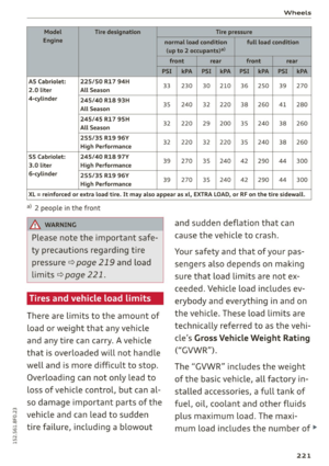 223
223 224
224 225
225 226
226 227
227 228
228 229
229 230
230 231
231 232
232 233
233 234
234 235
235 236
236 237
237 238
238 239
239 240
240 241
241 242
242 243
243 244
244 245
245 246
246 247
247 248
248 249
249 250
250 251
251 252
252 253
253 254
254 255
255 256
256 257
257 258
258 259
259 260
260 261
261 262
262 263
263 264
264 265
265 266
266 267
267