Page 337 of 360
ELECTRICAL COMPONENTS
8-47
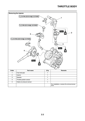
EAS1SL1348CHECKING THE FUEL INJECTOR
1. Remove:
• Fuel injector
Refer to “THROTTLE BODY” on page 7-5.
2. Check:
• Fuel injector resistance
Out of specification Replace.
▼▼▼▼▼▼▼▼▼▼▼▼▼▼▼▼▼▼▼▼▼▼▼▼▼▼▼▼▼▼▼▼
a. Disconnect the fuel injector coupler from the
fuel injector.
b. Connect the pocket tester ( 10) to the
fuel injector coupler.
c. Measure the fuel injector resistance.
▲▲▲▲▲▲▲▲▲▲▲▲▲▲▲▲▲▲▲▲▲▲▲▲▲▲▲▲▲▲▲▲
Continuity
Positive tester probe
Sky blue “1”
Negative tester probe
Sensor terminal “a”
Continuity
Positive tester probe
Black/Yellow “2”
Negative tester probe
Sensor terminal “b”
Continuity
Positive tester probe
Pink “3”
Negative tester probe
Sensor terminal “b”
Fuel injector resistance
12.0
Pocket tester
90890-03112
Analog pocket tester
YU-03112-C
• Positive tester probe
Injector terminal “1”
• Negative tester probe
Injector terminal “2”
b ca
B/YP
Sb
2
13
12
Page 338 of 360
ELECTRICAL COMPONENTS
8-48
Page 339 of 360

9
TROUBLE SHOOTING
TROUBLE SHOOTING..................................................................................... 9-1
GENERAL INFORMATION ........................................................................ 9-1
STARTING FAILURES ............................................................................... 9-1
INCORRECT ENGINE IDLING SPEED ..................................................... 9-1
POOR MEDIUM-AND-HIGH-SPEED PERFORMANCE ............................ 9-2
FAULTY GEAR SHIFTING ......................................................................... 9-2
SHIFT PEDAL DOES NOT MOVE ............................................................. 9-2
JUMPS OUT OF GEAR.............................................................................. 9-2
FAULTY CLUTCH ...................................................................................... 9-2
OVERHEATING ......................................................................................... 9-2
OVERCOOLING ......................................................................................... 9-3
POOR BRAKING PERFORMANCE ........................................................... 9-3
FAULTY FRONT FORK LEGS ................................................................... 9-3
UNSTABLE HANDLING ............................................................................. 9-3
LIST OF SELF-DIAGNOSTIC AND FAIL-SAFE ACTIONS............................. 9-4
Page 340 of 360

TROUBLE SHOOTING
9-1
EAS1SL1349
TROUBLE SHOOTING
EAS1SL1350GENERAL INFORMATION
TIP
The following guide for troubleshooting does
not cover all the possible causes of trouble. It
should be helpful, however, as a guide to basic
troubleshooting. Refer to the relative procedure
in this manual for checks, adjustments, and re
-
placement of parts.
EAS1SL1351STARTING FAILURES
Engine
1. Cylinder and cylinder head
• Loose spark plug
• Loose cylinder head or cylinder
• Damaged cylinder head gasket
• Damaged cylinder gasket
• Worn or damaged cylinder
• Incorrect valve clearance
• Improperly sealed valve
• Incorrect valve-to-valve-seat contact
• Incorrect valve timing
• Faulty valve spring
• Seized valve
2. Piston and piston ring(s)
• Improperly installed piston ring
• Damaged, worn or fatigued piston ring
• Seized piston ring
• Seized or damaged piston
3. Air filter
• Improperly installed air filter
• Clogged air filter element
4. Crankcase and crankshaft
• Improperly assembled crankcase
• Seized crankshaft
Fuel system
1. Fuel tank
• Empty fuel tank
• Clogged fuel tank breather hose
• Deteriorated or contaminated fuel
• Clogged or damaged fuel hose
2. Fuel pump
• Faulty fuel pump
3. Throttle body
• Deteriorated or contaminated fuel
• Sucked-in air
Electrical system
1. Spark plug
• Incorrect spark plug gap
• Incorrect spark plug heat range
• Fouled spark plug
• Worn or damaged electrode
• Worn or damaged insulator
2. Ignition coil
• Cracked or broken ignition coil body
• Broken or shorted primary or secondary
coils
3. Ignition system
• Faulty ECU
• Faulty crankshaft position sensor
• Broken generator rotor woodruff key
4. Switches and wiring
• Faulty ECU
• Faulty engine stop switch
• Broken or shorted wiring
• Faulty neutral switch
• Improperly grounded circuit
• Loose connections
EAS1SL1352INCORRECT ENGINE IDLING SPEED
Engine
1. Cylinder and cylinder head
• Incorrect valve clearance
• Damaged valve train components
2. Air filter
• Clogged air filter element
Fuel system
1. Throttle body
• Damaged or loose throttle body joint
• Improperly synchronized throttle bodies
• Improper throttle cable free play
• Flooded throttle body
Electrical system
1. Spark plug
• Incorrect spark plug gap
• Incorrect spark plug heat range
• Fouled spark plug
• Worn or damaged electrode
• Worn or damaged insulator
• Faulty spark plug cap
2. Ignition coil
• Broken or shorted primary or secondary
coils
• Cracked or broken ignition coil
Page 341 of 360

TROUBLE SHOOTING
9-2
3. Ignition system
• Faulty ECU
• Faulty crankshaft position sensor
• Broken generator rotor woodruff key
EAS1SL1353POOR MEDIUM-AND-HIGH-SPEED PER-
FORMANCE
Refer to “STARTING FAILURES” on page 9-1.
Engine
1. Air filter
• Clogged air filter element
Fuel system
1. Fuel pump
• Faulty fuel pump
2. Throttle body
• Defective throttle body
3. ECU
• Faulty ECU
EAS1SL1354FAULTY GEAR SHIFTING
Shifting is difficult
Refer to “CLUTCH” on page 5-37.
EAS1SL1355SHIFT PEDAL DOES NOT MOVE
Shift shaft
• Bent shift shaft
Shift drum and shift forks
• Foreign object in a shift drum groove
• Seized shift fork
• Bent shift fork guide bar
Transmission
• Seized transmission gear
• Foreign object between transmission gears
• Improperly assembled transmission
EAS1SL1356JUMPS OUT OF GEAR
Shift shaft
• Incorrect shift pedal position
• Improperly returned stopper lever
Shift forks
• Worn shift fork
Shift drum
• Incorrect axial play
• Worn shift drum groove
Transmission
• Worn gear dog
EAS1SL1357FAULTY CLUTCH
Clutch slips
1. Clutch
• Improperly assembled clutch
• Loose or fatigued clutch spring
• Worn friction plate
• Worn clutch plate
2. Engine oil
• Incorrect oil level
• Incorrect oil viscosity (low)
• Deteriorated oil
Clutch drags
1. Clutch
• Unevenly tensioned clutch springs
• Warped pressure plate
• Bent clutch plate
• Swollen friction plate
• Bent clutch push rod
• Damaged clutch boss
• Burnt primary driven gear bushing
2. Engine oil
• Incorrect oil level
• Incorrect oil viscosity (high)
• Deteriorated oil
EAS1SL1358OVERHEATING
Engine
1. Cylinder head and piston
• Heavy carbon buildup
• Clogged coolant passages
2. Engine oil
• Incorrect oil level
• Incorrect oil viscosity
• Inferior oil quality
Cooling system
1. Coolant
• Low coolant level
2. Radiator
• Damaged or leaking radiator
• Faulty radiator cap
• Bent or damaged radiator fin
3. Water pump
• Damaged or faulty water pump
• Damaged hose
• Improperly connected hose
• Damaged pipe
• Improperly connected pipe
Page 342 of 360

TROUBLE SHOOTING
9-3
Fuel system
1. Throttle body
• Damaged or loose throttle body joint
2. Air filter
• Clogged air filter element
Chassis
1. Brake(s)
• Dragging brake
Electrical system
1. Spark plug
• Incorrect spark plug gap
• Incorrect spark plug heat range
2. Ignition system
• Faulty ECU
• Faulty coolant temperature sensor
EAS1SL1359OVERCOOLING
Cooling system
• Faulty coolant temperature sensor
EAS1SL1360POOR BRAKING PERFORMANCE
• Worn brake pad
• Worn brake disc
• Air in hydraulic brake system
• Leaking brake fluid
• Defective master cylinder kit
• Faulty brake caliper kit
• Faulty brake caliper seal
• Loose union bolt
• Damaged brake hose
• Oil or grease on the brake disc
• Oil or grease on the brake pad
• Incorrect brake fluid level
EAS1SL1361FAULTY FRONT FORK LEGS
Leaking oil
• Bent, damaged, or rusty inner tube
• Cracked or damaged outer tube
• Improperly installed oil seal
• Damaged oil seal lip
• Incorrect oil level (high)
• Loose damper rod assembly bolt
• Damaged damper rod assembly bolt copper
washer
• Cracked or damaged cap bolt O-ring
Malfunction
• Bent or damaged inner tube
• Bent or damaged outer tube
• Broken fork spring
• Bent or damaged damper rod
• Incorrect oil viscosity
• Incorrect oil level
EAS1SL1362UNSTABLE HANDLING
1. Handlebar
• Bent or improperly installed handlebar
2. Steering head components
• Improperly installed upper bracket
• Improperly installed lower bracket
(improperly tightened ring nut)
• Bent steering stem
• Damaged ball bearing or bearing race
3. Front fork leg (s)
• Uneven oil levels (both front fork legs)
• Unevenly tensioned fork spring (both front
fork legs)
• Broken fork spring
• Bent or damaged inner tube
• Bent or damaged outer tube
4. Swingarm
• Worn bearing or bushing
• Bent or damaged swingarm
5. Rear shock absorber assembly (-ies)
• Faulty rear shock absorber spring
• Leaking oil or gas
6. Tire (s)
• Uneven tire pressures (front and rear)
• Incorrect tire pressure
• Uneven tire wear
7. Wheel (s)
• Incorrect wheel balance
• Broken or loose spoke
• Damaged wheel bearing
• Bent or loose wheel axle
• Excessive wheel runout
8. Frame
• Bent frame
• Damaged steering head pipe
• Improperly installed bearing race
Page 343 of 360

LIST OF SELF-DIAGNOSTIC AND FAIL-SAFE ACTIONS
9-4
EAS1SL1363
LIST OF SELF-DIAGNOSTIC AND FAIL-SAFE ACTIONS
LIST OF DIAGNOSTIC CODES
COMMUNICATION ERROR WITH YAMAHA DIAGNOSTIC TOOL
Fault
codeITEMPage
12Crankshaft position sensor: no normal signals are received from the
crankshaft position sensor.8-14
13Intake air pressure sensor: open or short circuit detected.8-15
14Intake air pressure sensor: hose system malfunction (clogged or de-
tached hose)8-16
15Throttle position sensor: open or short circuit detected.8-17
16Throttle position sensor: stuck throttle position sensor is detected.8-19
21Coolant temperature sensor: open or short circuit detected.8-20
22Intake air temperature sensor: open or short circuit detected.8-21
30The vehicle has overturned.8-22
33Ignition coil: open or short circuit detected in the primary lead of the
ignition coil.8-23
39Injector: open or short circuit detected.8-25
41ECU: built-in lean angle sensor malfunction8-25
44EEPROM fault code No.: an error is detected while reading or writing
on EEPROM.8-26
46Vehicle system power supply: normal voltage is not supplied to the
ECU.8-27
50ECU: faulty ECU memory8-28
Fault
codeITEMPage
Waiting
for con
-
nection
No communication signal is received from the ECU.
8-28
Er-2Signals from the ECU cannot be received within the specified period
of time.8-29
Er-3Data from the ECU cannot be received correctly.8-30
Er-4Registered data cannot be received from the Yamaha diagnostic tool.8-31
Page 344 of 360

LIST OF SELF-DIAGNOSTIC AND FAIL-SAFE ACTIONS
9-5
SENSOR OPERATION TABLEDiag-
nostic code No. ITEM Display Procedure
01 Throttle angle • Fully closed position
• Fully opened position Displays the throttle angle.
• 11-14
• 109-116
• Check with throttle fully
closed.
• Check with throttle fully opened.
03 Pressure of suction pipe Displays the intake air pres- sure.The atmospheric pressure
is displayed on the Yamaha
diagnostic tool.
05 Intake air temperature Displays the intake air tem- perature.Compare the actually mea-
sured intake air tempera-
ture with the Yamaha
diagnostic tool display val-
ue.
06 Coolant temperature Displays the coolant temper- ature.Compare the actually mea-
sured coolant temperature
with the Yamaha diagnostic
tool display value.
08 Lean angle sensor • Upright
•Overturn Displays the output voltage.
• 1.0 (V)
• 4.0 (V) Remove the ECU, and in-
cline it 45° or more.
09 Monitor voltage Displays the voltage of the external battery connected to
the Yamaha diagnostic tool.
• Approximately 12.0 (V)—
21 Neutral switch • Gear in neutral
• Gear not in neutral •ON
•OFF Operate the shift pedal.
25 Gear position sensor • Gear in 1st or 2nd
• Gear not in 1st or 2nd •ON
•OFF Operate the shift pedal.
60 EEPROM fault code No. display
• No fault
• CO adjustment valve
• Power Tuner injection cor-rection setting 0–8, or
Power Tuner ignition tim-
ing correction setting 0–8 •00
•01
•07
—
61 Malfunction history ( ) code No. display
*1
• There is no history.
• There is some history. •00
• Other: Displays the fault
code of ( ). —