Page 161 of 360
HANDLEBAR
4-35
6. Install:
• Right grip “1”
• Collar “2”
Apply adhesive to the tube guide “3.”
TIP
• Before applying the adhesive, wipe off grease
or oil on the tube guide surface “a” with a lac
-
quer thinner.
• Install the grip to the tube guide so that the
grip match mark “b” and tube guide slot “c”
form the angle as shown.
7. Install:
• Collar “1”
• Rubber cover “2”
• Throttle grip “3”
TIP
Apply the lithium soap base grease on the
throttle grip sliding surface.
8. Install:
• Throttle cables “1”
TIP
Slightly coat the end of throttle cable and inside
of throttle grip with lithium-soap-based
grease.Then, mount the throttle grip onto the
handlebar.
9. Install:
• Throttle cable housings “1”
• Screw (throttle cable housings) “2”
EWA1DX5001
WARNING
After tightening the throttle cable housing
screws, check that the throttle grip “3”
moves smoothly. If it does not, retighten the
screws for adjustment.
1b
c
3
Screw (throttle cable housings)
3.8 Nm (0.38 m·kgf, 2.8 ft·lbf)T R..
Page 162 of 360
HANDLEBAR
4-36
10.Install:
• Rubber cover “1”
• Cover (throttle cable housings) “2”
11.Install:
• Front brake master cylinder assembly “1”
• Front brake master cylinder holder “2”
• Bolt (brake master cylinder holder) “3”
TIP
• Install the brake master cylinder holder with
the “UP” mark facing up.
• Install in order for the top of the front brake
master cylinder assembly to be level.
• First, tighten the upper bolt, then the lower
bolt.
12.Install:
• Clutch cable “1”
TIP
Before installation, apply the lithium-soap-
based grease to the clutch cable end.
13.Adjust:
• Clutch lever free play
Refer to “ADJUSTING THE CLUTCH LE-
VER FREE PLAY” on page 3-10.
14.Adjust:
• Throttle grip free play
Refer to “ADJUSTING THE THROTTLE
GRIP FREE PLAY” on page 3-11.
Front brake master cylinder hold-
er bolt
9 Nm (0.9 m·kgf, 6.5 ft·lbf)
T R..
Clutch lever free play
7.0-12.0 mm (0.28-0.47 in)
Throttle grip free play
3.0-5.0 mm (0.12-0.20 in)
1LS
Page 163 of 360
FRONT FORK
4-37
EAS1SL1165
FRONT FORK
Removing the front fork legs
OrderPart nameQ’tyRemarks
Use a suitable stand to raise the front wheel
off the ground.
Front wheelRefer to “FRONT WHEEL” on page 4-3.
Front brake caliperRefer to “FRONT BRAKE” on page 4-11.
Number plateRefer to “GENERAL CHASSIS” on page 4-1.
1Protector1
2Upper bracket pinch bolts2Loosen.
3Damper assembly1Loosen.
4Lower bracket pinch bolts2Loosen.
5Front fork leg1
For installation, reverse the removal proce-dure.
3
2
4
5
1
T.R.21 Nm (2.1 mlbf) kgf, 15 ft
T.R.9 Nm (0.9 mlbf) kgf, 6.5 ft
T.R.5 Nm (0.5 mlbf) kgf, 3.6 ft
Page 164 of 360
FRONT FORK
4-38
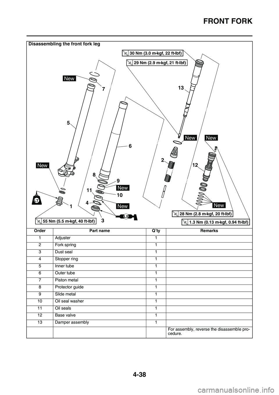
Disassembling the front fork leg
OrderPart nameQ’tyRemarks
1Adjuster1
2Fork spring1
3Dust seal1
4Stopper ring1
5Inner tube1
6Outer tube1
7Piston metal1
8Protector guide1
9Slide metal1
10Oil seal washer1
11Oil seals1
12Base valve1
13Damper assembly1
For assembly, reverse the disassemble pro-cedure.
LS
13
2 6
9 8
10 11
4
3 1 57
12
New
NewNew
New
New
New
New
LT
29 Nm (2.9 mkgf, 21 ftIbf)T.R.
55 Nm (5.5 mkgf, 40 ftIbf)T.R.1.3 Nm (0.13 mkgf, 0.94 ftIbf)T.R.
28 Nm (2.8 mkgf, 20 ftIbf)T.
R
.
30 Nm (3.0 mkgf, 22 ftIbf)T.R
.
Page 165 of 360

FRONT FORK
4-39
EAS1SL1166REMOVING THE FRONT FORK LEGS
1. Use a suitable stand to raise the front wheel
off the ground.
EWA13120
WARNING
Securely support the vehicle so that there is
no danger of it falling over.
TIP
Record the adjusting screw setting position be-
fore loosening the adjuster and the base valve.
2. Loosen:
• Upper bracket pinch bolts
• Damper assembly
• Lower bracket pinch boltsEWA13120
WARNING
Before loosening the upper and lower
bracket pinch bolts, support the front fork
leg.
TIP
Before removing the front fork leg from the ve-
hicle, loosen the damper assembly “1” with the
cap bolt ring wrench “2.”
3. Remove:
• Front fork leg (s)
EAS1SL1167DISASSEMBLING THE FRONT FORK LEGS
1. Drain:
• Fork oil
2. Remove:
• Adjuster “1”
(from the inner tube)
TIP
• While compressing the inner tube “2”, set the
cap bolt ring wrench “4” between the inner
tube and locknut “3”.
• Hold the locknut and remove the adjuster.
ECA14180
NOTICE
Do not remove the locknut as the damper
rod may go into the damper assembly and
not be taken out.
3. Remove:
• Dust seal “1”
• Oil seal clip “2”
(with a flat-head screwdriver)ECA14180
NOTICE
Do not scratch the inner tube.
4. Remove:
• Inner tube “1”
▼▼▼▼▼▼▼▼▼▼▼▼▼▼▼▼▼▼▼▼▼▼▼▼▼▼▼▼▼▼▼▼
a. Push in slowly “a” the inner tube just before
it bottoms out and then pull it back quickly
“b”.
b. Repeat this step until the inner tube can be
pulled out from the outer tube.
Cap bolt ring wrench
90890-01501
YM-01501
12
Cap bolt ring wrench
90890-01501
YM-01501
1
234
1
2
Page 166 of 360

FRONT FORK
4-40
▲▲▲▲▲▲▲▲▲▲▲▲▲▲▲▲▲▲▲▲▲▲▲▲▲▲▲▲▲▲▲▲
5. Remove:
• Base valve “1”
(from the damper assembly)
TIP
Hold the damper assembly with the cap bolt
ring wrench “2” and use the cap bolt wrench “3”
to remove the base valve.
EAS1SL1168CHECKING THE FRONT FORK LEGS
1. Check:
• Inner tube surface “a”
Scratches Repair or replace.
Use #1000 grit wet sandpaper.
Damaged oil lock piece Replace.
• Inner tube bends
Out of specification Replace.
Use the dial gauge “1.”
TIP
The bending value is shown by one half of the
dial gauge reading.
EWA13650
WARNING
Do not attempt to straighten a bent inner
tube as this may dangerously weaken it.
2. Check:
• Outer tube
Scratches/wear/damage Replace.
3. Measure:
• Fork spring free length “a”
Out of specification Replace.
4. Check:
• Damper assembly “1”
Bend/damage Replace.
• O-ring “2”
Wear/damage Replace.ECA1DX1010
NOTICE
• The front fork leg has a built-in damper ad-
justing rod and a very sophisticated inter-
nal construction, which are particularly
sensitive to foreign material.
• When disassembling and assembling the
front fork leg, do not allow any foreign ma
-
terial to enter the front fork.
Cap bolt wrench
90890-01500
YM-01500
Cap bolt ring wrench
90890-01501
YM-01501
Inner tube bending limit
0.2 mm (0.01 in)
1 23
Fork spring free length
497.0 mm (19.57 in)
Limit
492.0 mm (19.37 in)
Page 167 of 360

FRONT FORK
4-41
5. Check:
• Base valve “1”
Wear/damage Replace.
Contamination Clean.
• O-rings “2”
Wear/damage Replace.
• Base valve bushing “3”
Wear/damage Replace.
• Spring “4”
Damage/fatigue Replace the base valve.
• Air bleed screw “5”
Wear/damage Replace.
6. Check:
• Contacting surface “a”
Wear/damage Replace.
7. Check:
• Adjuster “1”
• O-rings “2”
Wear/damage Replace.
EAS1SL1169ASSEMBLING THE FRONT FORK LEGSEWA13660
WARNING
• Make sure the oil levels in both front fork
legs are equal.
• Uneven oil levels can result in poor han-
dling and a loss of stability.
TIP
• When assembling the front fork leg, be sure to
replace the following parts:
• Inner tube bushing
• Outer tube bushing
• Oil seals
• Copper washers
• Before assembling the front fork leg, make
sure that all of the components are clean.
1. Stretch the damper assembly fully.
2. Fill:
• Damper assembly
ECA14210
NOTICE
• Be sure to use the recommended oil. Other
oils may have an adverse effect on front
fork performance.
• When disassembling and assembling the
front fork leg, take care not to allow any
foreign material to enter the front fork.
3. After filling, pump the damper assembly “1”
slowly up and down (about 200 mm (7.9 in)
stroke) several times to bleed the damper
assembly of air.
TIP
Avoid excessive full stroke. A stroke of 200 mm
(7.9 in) or more will cause air to enter. In this
case, repeat the steps 1 to 3.
21
New
New
New
2
21 543
a
New
Recommended oil
Suspension oil S1
Standard oil amount
204 cm3 (6.90 US oz, 7.20
Imp.oz)
New
1
2
Page 168 of 360

FRONT FORK
4-42
4. Measure:
• Oil level (left and right) “a”
Out of specification Regulate.
5. Tighten:
• Locknut “1”
TIP
Fully finger tighten the locknut onto the damper
assembly.
6. Loosen:
• Compression damping force adjuster “1”
TIP
• Before loosening the damping force adjuster,
record the setting position.
• Unless the damping force adjuster is fully
loosened, correct damping characteristic can
-
not be obtained after installation.
7. Install:
• Base valve “1”
(to the damper assembly “2”)
TIP
First bring the damper rod pressure to a maxi-
mum. Then install the base valve while releas-
ing the damper rod pressure.
8. Check:
• Damper assembly
Not fully stretched Repeat the steps 1 to
7.
9. Tighten:
• Base valve “1”
TIP
Hold the damper assembly with the cap bolt
ring wrench “2” and use the cap bolt wrench “3”
to tighten the base valve.
Standard oil level
145-148 mm (5.71-5.83 in)
From top of fully stretched
damper assembly.
1
a
Base valve
28 Nm (2.8 m·kgf, 20 ft·lbf)
1
1
2
T R..