2014 NISSAN TEANA check engine
[x] Cancel search: check enginePage 3219 of 4801
CHASSIS AND BODY MAINTENANCEMA-35
< PERIODIC MAINTENANCE >
C
D E
F
G H
I
J
K L
M B
MA
N
O A
CAUTION:
Do not reuse O-ring.
14. Lift down the vehicle.
15. Stop the engine.
CVT FLUID : RE0F10EINFOID:0000000009464570
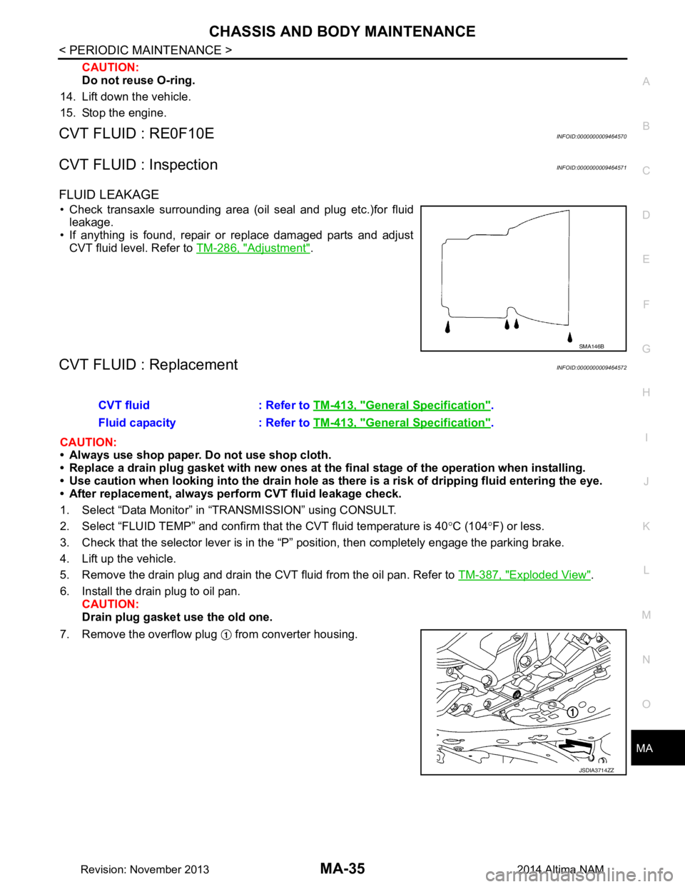
CVT FLUID : InspectionINFOID:0000000009464571
FLUID LEAKAGE
• Check transaxle surrounding area (oil seal and plug etc.)for fluid leakage.
• If anything is found, repair or replace damaged parts and adjust
CVT fluid level. Refer to TM-286, "Adjustment"
.
CVT FLUID : ReplacementINFOID:0000000009464572
CAUTION:
• Always use shop paper. Do not use shop cloth.
• Replace a drain plug gasket with new ones at the fi nal stage of the operation when installing.
• Use caution when looking into the drain hole as there is a risk of dripping fluid entering the eye.
• After replacement, always pe rform CVT fluid leakage check.
1. Select “Data Monitor” in “TRANSMISSION” using CONSULT.
2. Select “FLUID TEMP” and confirm t hat the CVT fluid temperature is 40°C (104 °F) or less.
3. Check that the selector lever is in the “P ” position, then completely engage the parking brake.
4. Lift up the vehicle.
5. Remove the drain plug and drain the CVT fluid from the oil pan. Refer to TM-387, "Exploded View"
.
6. Install the drain plug to oil pan. CAUTION:
Drain plug gasket use the old one.
7. Remove the overflow plug from converter housing.
SMA146B
CVT fluid : Refer to TM-413, "General Specification".
Fluid capacity : Refer to TM-413, "General Specification"
.
JSDIA3714ZZ
Revision: November 20132014 Altima NAM
Page 3220 of 4801
MA-36
< PERIODIC MAINTENANCE >
CHASSIS AND BODY MAINTENANCE
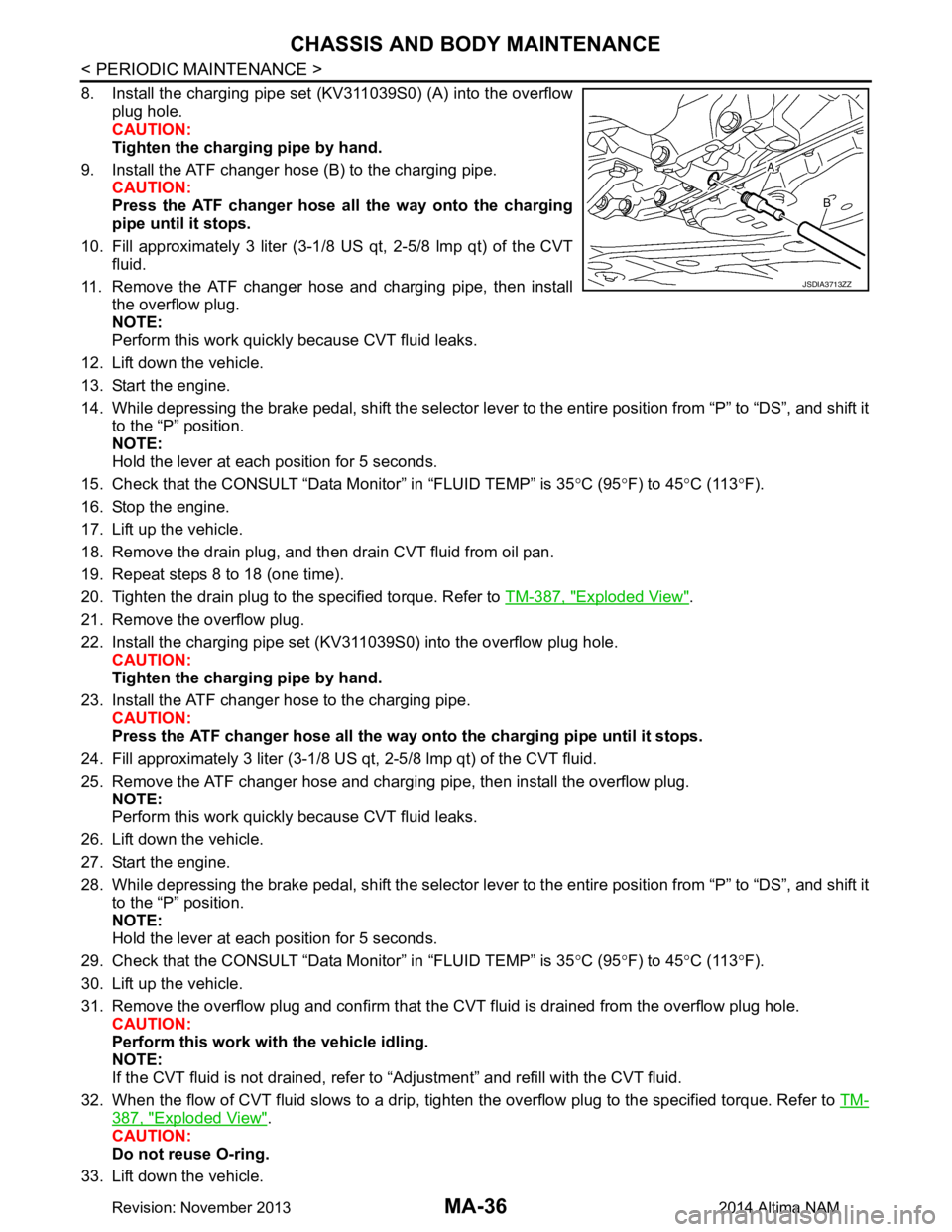
8. Install the charging pipe set (KV311039S0) (A) into the overflowplug hole.
CAUTION:
Tighten the charging pipe by hand.
9. Install the ATF changer hose (B) to the charging pipe. CAUTION:
Press the ATF changer hose all the way onto the charging
pipe until it stops.
10. Fill approximately 3 liter (3-1/8 US qt, 2-5/8 lmp qt) of the CVT
fluid.
11. Remove the ATF changer hose and charging pipe, then install the overflow plug.
NOTE:
Perform this work quickly because CVT fluid leaks.
12. Lift down the vehicle.
13. Start the engine.
14. While depressing the brake pedal, shift the selector lever to the entire position from “P” to “DS”, and shift it to the “P” position.
NOTE:
Hold the lever at each position for 5 seconds.
15. Check that the CONSULT “Data Monitor” in “FLUID TEMP” is 35 °C (95 °F) to 45 °C (113 °F).
16. Stop the engine.
17. Lift up the vehicle.
18. Remove the drain plug, and then drain CVT fluid from oil pan.
19. Repeat steps 8 to 18 (one time).
20. Tighten the drain plug to the specified torque. Refer to TM-387, "Exploded View"
.
21. Remove the overflow plug.
22. Install the charging pipe set (KV311039S0) into the overflow plug hole. CAUTION:
Tighten the charging pipe by hand.
23. Install the ATF changer hose to the charging pipe. CAUTION:
Press the ATF changer hose all the way onto the charging pipe until it stops.
24. Fill approximately 3 liter (3-1/8 US qt, 2-5/8 lmp qt) of the CVT fluid.
25. Remove the ATF changer hose and charging pipe, then install the overflow plug. NOTE:
Perform this work quickly because CVT fluid leaks.
26. Lift down the vehicle.
27. Start the engine.
28. While depressing the brake pedal, shift the selector lever to the entire position from “P” to “DS”, and shift it to the “P” position.
NOTE:
Hold the lever at each position for 5 seconds.
29. Check that the CONSULT “Data Monitor” in “FLUID TEMP” is 35 °C (95 °F) to 45 °C (113 °F).
30. Lift up the vehicle.
31. Remove the overflow plug and confirm that the CV T fluid is drained from the overflow plug hole.
CAUTION:
Perform this work with the vehicle idling.
NOTE:
If the CVT fluid is not drained, refer to “Adjustment” and refill with the CVT fluid.
32. When the flow of CVT fluid slows to a drip, tighten the overflow plug to the specified torque. Refer to TM-
387, "Exploded View".
CAUTION:
Do not reuse O-ring.
33. Lift down the vehicle.
JSDIA3713ZZ
Revision: November 20132014 Altima NAM
Page 3221 of 4801
CHASSIS AND BODY MAINTENANCEMA-37
< PERIODIC MAINTENANCE >
C
D E
F
G H
I
J
K L
M B
MA
N
O A
34. Select “Data Monitor” in “TRANSMISSION” using CONSULT.
35. Select “CONFORM CVTF DETERIORTN”.
36. Select “Erase”.
37. Stop the engine.
CVT FLUID : AdjustmentINFOID:0000000009464573
CAUTION:
• During adjustment of the CVT fluid level, check CO NSULT so that the oil temperature may be main-
tained from 35 to 45 °C (95 to 113 °F).
• During adjustment of the CVT fluid level, check that the engine speed is maintaining 500 rpm.
• Use caution when looking into the drain hole as there is a risk of dripping fluid entering the eye.
1. Check that the selector lever is in the “P ” position, then completely engage the parking brake.
2. Start the engine.
3. Adjust the CVT fluid temperature to be approximately 40 °C (104 °F).
NOTE:
The CVT fluid is largely affected by temperature. Therefore be sure to use CONSULT and check the
“FLUID TEMP” under “TRA NSMISSION” in “Data Monitor” while adjusting.
4. While depressing the brake pedal, shift the selector leve r to the entire position from “P” to “DS”, and shift it
to the “P” position.
NOTE:
Hold the lever at each position for 5 seconds.
5. Lift up the vehicle.
6. Check that there is no CVT fluid leakage.
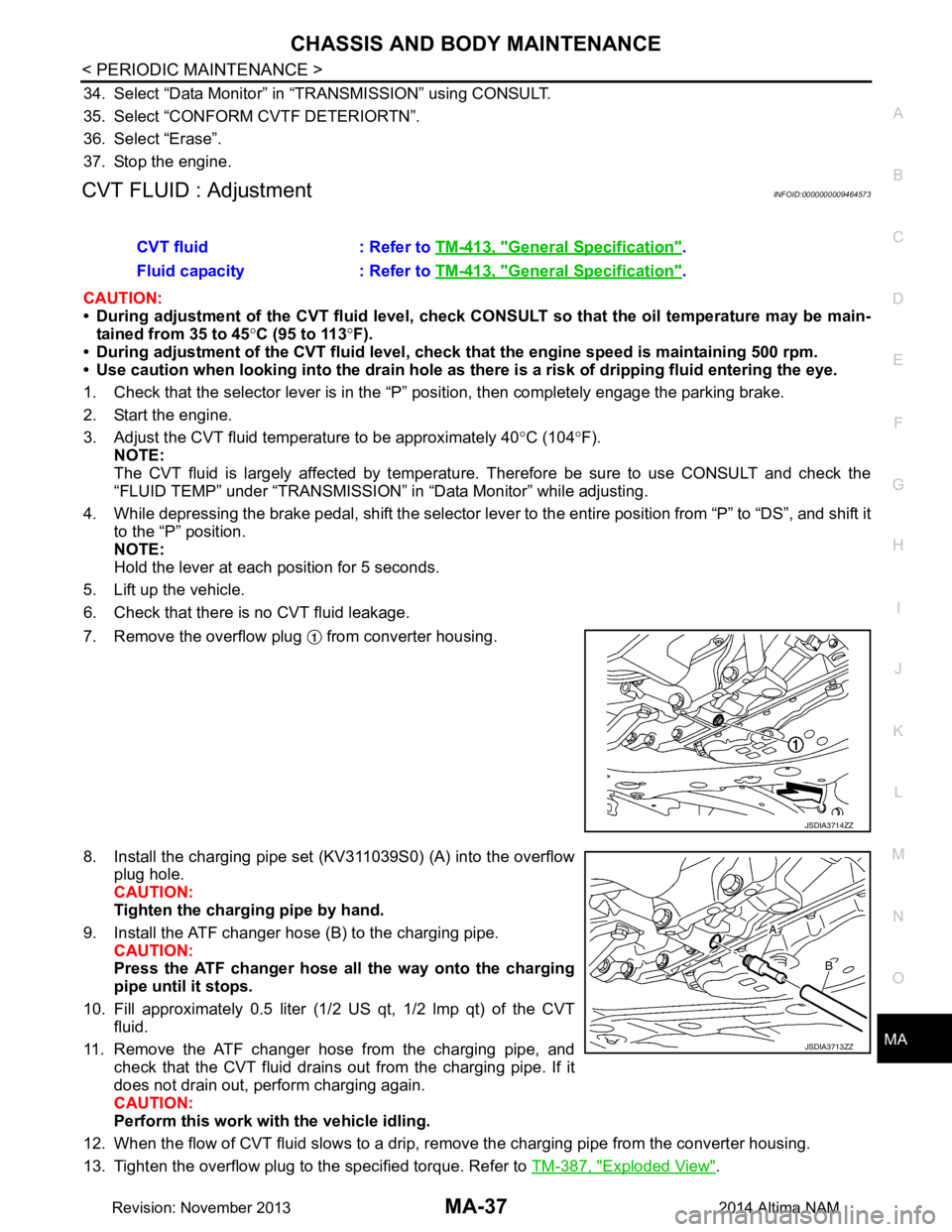
7. Remove the overflow plug from converter housing.
8. Install the charging pipe set (KV311039S0) (A) into the overflow plug hole.
CAUTION:
Tighten the charging pipe by hand.
9. Install the ATF changer hose (B) to the charging pipe. CAUTION:
Press the ATF changer hose all the way onto the charging
pipe until it stops.
10. Fill approximately 0.5 liter (1/2 US qt, 1/2 lmp qt) of the CVT
fluid.
11. Remove the ATF changer hose from the charging pipe, and check that the CVT fluid drains out from the charging pipe. If it
does not drain out, perform charging again.
CAUTION:
Perform this work with the vehicle idling.
12. When the flow of CVT fluid slows to a drip, re move the charging pipe from the converter housing.
13. Tighten the overflow plug to the specified torque. Refer to TM-387, "Exploded View"
.
CVT fluid : Refer to
TM-413, "General Specification"
.
Fluid capacity : Refer to TM-413, "General Specification"
.
JSDIA3714ZZ
JSDIA3713ZZ
Revision: November 20132014 Altima NAM
Page 3222 of 4801
MA-38
< PERIODIC MAINTENANCE >
CHASSIS AND BODY MAINTENANCE
CAUTION:
Do not reuse O-ring.
14. Lift down the vehicle.
15. Stop the engine.
WHEELS
WHEELS : InspectionINFOID:0000000009464574
ALUMINUM WHEEL
1. Check tires for wear and improper inflation.
2. Check wheels for deformation, cracks and other dam age. If deformed, remove wheel and check wheel
runout.
3. Remove tire from aluminum wheel and mount wheel on a tire balance machine.
CAUTION:
DO NOT use center hole cone -type clamping machines to
hold the wheel assembly during tire removal/installation or
balancing. Damage to the wheel finish, cladding or chrome
may occur. Use only rim-type or universal lug-type clamp-
ing machines to hold the wheel assembly.
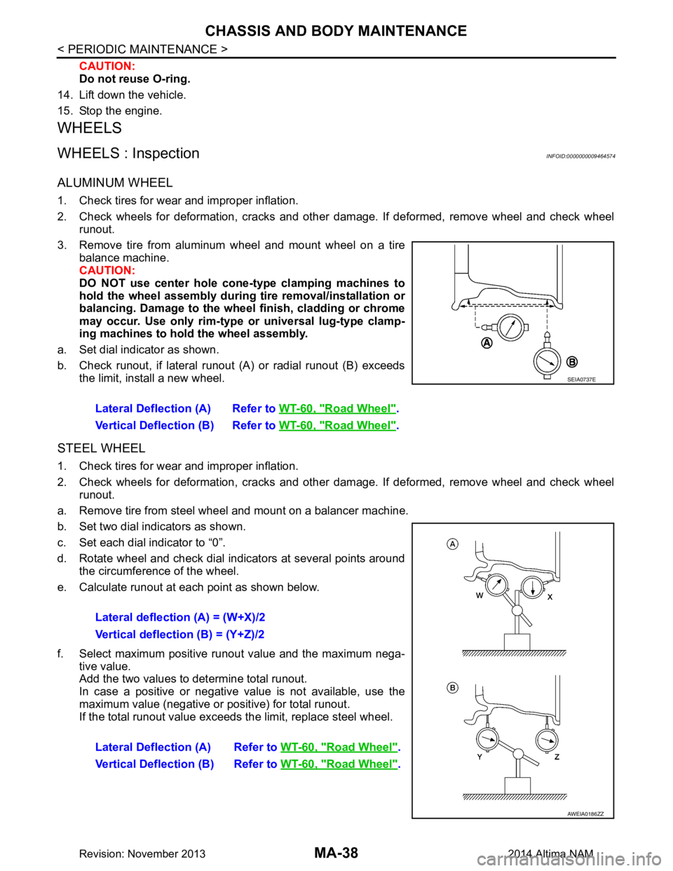
a. Set dial indicator as shown.
b. Check runout, if lateral runout (A) or radial runout (B) exceeds the limit, install a new wheel.
STEEL WHEEL
1. Check tires for wear and improper inflation.
2. Check wheels for deformation, cracks and other dam age. If deformed, remove wheel and check wheel
runout.
a. Remove tire from steel wheel and mount on a balancer machine.
b. Set two dial indicators as shown.
c. Set each dial indicator to “0”.
d. Rotate wheel and check dial indicators at several points around the circumference of the wheel.
e. Calculate runout at each point as shown below.
f. Select maximum positive runout value and the maximum nega- tive value.
Add the two values to determine total runout.
In case a positive or negative value is not available, use the
maximum value (negative or positive) for total runout.
If the total runout value exceeds the limit, replace steel wheel. Lateral Deflection (A) Refer to
WT-60, "Road Wheel"
.
Vertical Deflection (B) Refer to WT-60, "Road Wheel"
.
SEIA0737E
Lateral deflection (A) = (W+X)/2
Vertical deflection (B) = (Y+Z)/2
Lateral Deflection (A) Refer to WT-60, "Road Wheel"
.
Vertical Deflection (B) Refer to WT-60, "Road Wheel"
.
AWEIA0186ZZ
Revision: November 20132014 Altima NAM
Page 3225 of 4801
CHASSIS AND BODY MAINTENANCEMA-41
< PERIODIC MAINTENANCE >
C
D E
F
G H
I
J
K L
M B
MA
N
O A
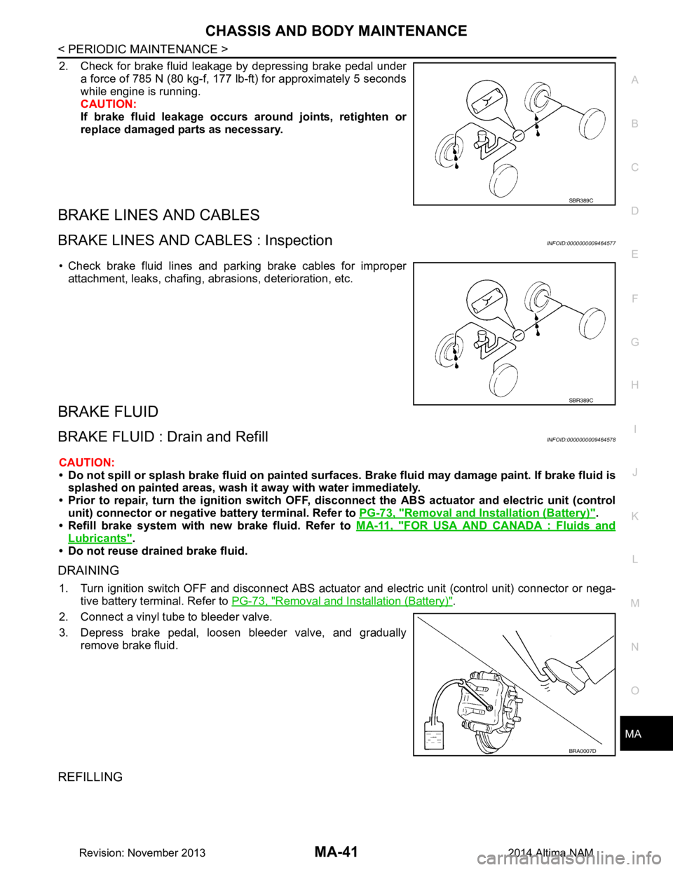
2. Check for brake fluid leakage by depressing brake pedal under
a force of 785 N (80 kg-f, 177 lb-ft) for approximately 5 seconds
while engine is running.
CAUTION:
If brake fluid leakage occurs around joints, retighten or
replace damaged parts as necessary.
BRAKE LINES AND CABLES
BRAKE LINES AND CABLES : InspectionINFOID:0000000009464577
• Check brake fluid lines and parking brake cables for improper attachment, leaks, chafing, abrasions, deterioration, etc.
BRAKE FLUID
BRAKE FLUID : Drain and RefillINFOID:0000000009464578
CAUTION:
• Do not spill or splash brake fluid on painted surf aces. Brake fluid may damage paint. If brake fluid is
splashed on painted areas, wash it away with water immediately.
• Prior to repair, turn the ignition switch OFF, disconnect the ABS actuator and electric unit (control
unit) connector or negative battery terminal. Refer to PG-73, "Removal and Installation (Battery)"
.
• Refill brake system with new brake fluid. Refer to MA-11, "FOR USA AND CANADA : Fluids and
Lubricants".
• Do not reuse drained brake fluid.
DRAINING
1. Turn ignition switch OFF and disconnect ABS actuat or and electric unit (control unit) connector or nega-
tive battery terminal. Refer to PG-73, "Removal and Installation (Battery)"
.
2. Connect a vinyl tube to bleeder valve.
3. Depress brake pedal, loosen bleeder valve, and gradually remove brake fluid.
REFILLING
SBR389C
SBR389C
BRA0007D
Revision: November 20132014 Altima NAM
Page 3228 of 4801
MA-44
< PERIODIC MAINTENANCE >
CHASSIS AND BODY MAINTENANCE
POWER STEERING FLUID AND LINES : Inspection
INFOID:0000000009464588
FLUID LEVEL
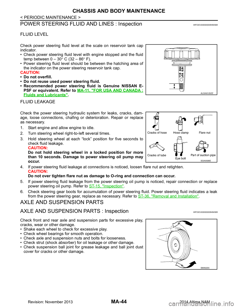
Check power steering fluid level at the scale on reservoir tank cap
indicator.
• Check power steering fluid level with engine stopped and the fluid temp between 0 – 30 ° C (32 – 86 ° F).
• Power steering fluid level should be between the hatching area of the indicator on the power steering reservoir tank cap.
CAUTION:
• Do not overfill.
• Do not reuse used power steering fluid.
• Recommended power steering fluid is Genuine NISSAN E-
PSF or equivalent. Refer to MA-11, "FOR USA AND CANADA :
Fluids and Lubricants".
FLUID LEAKAGE
Check the power steering hydraulic system for leaks, cracks, dam-
age, loose connections, chafing or det erioration. Repair or replace
as necessary.
1. Start engine and allow engine to idle.
2. Turn steering wheel right-to-left several times.
3. Hold steering wheel at each “lock” position for five seconds to check fluid leakage.
CAUTION:
Do not hold steering wheel in a locked position for more
than 10 seconds. Damage to power steering oil pump may
occur.
4. If power steering fluid leakage at connections is noticed, loosen flare nut and retighten.
CAUTION:
Do not over tighten flare nut as damage to O-ring and connection can occur.
5. If power steering fluid leakage from the power steer ing oil pump is noticed, repair connection or replace
power steering oil pump. Refer to ST-15, "Inspection"
.
6. Check steering gear boots for accumulation of power steering fluid. Power steering fluid indicates a leak from the power steering gear, replace as necessary. Refer to ST-36, "Removal and Installation"
.
AXLE AND SUSPENSION PARTS
AXLE AND SUSPENSION PARTS : InspectionINFOID:0000000009464589
Check front and rear axle and suspension parts for excessive play,
cracks, wear or other damage.
• Shake each wheel to check for excessive play.
• Check wheel bearings for smooth operation.
• Check axle and suspension nuts and bolts for looseness.
• Check strut (shock absorber) for oil leakage or other damage.
• Check suspension ball joint for grease leakage and ball joint dust cover for cracks or other damage.
ALGIA0125ZZ
SGIA0506E
SMA525A
Revision: November 20132014 Altima NAM
Page 3232 of 4801
MIR-2
< PRECAUTION >
PRECAUTIONS
PRECAUTION
PRECAUTIONS
Precaution for Supplemental Restraint System (SRS) "AIR BAG" and "SEAT BELT
PRE-TENSIONER"
INFOID:0000000009951574
The Supplemental Restraint System such as “A IR BAG” and “SEAT BELT PRE-TENSIONER”, used along
with a front seat belt, helps to reduce the risk or severi ty of injury to the driver and front passenger for certain
types of collision. Information necessary to service the system safely is included in the SR and SB section of
this Service Manual.
WARNING:
• To avoid rendering the SRS inopera tive, which could increase the risk of personal injury or death in
the event of a collision which would result in air bag inflation, all maintenance must be performed by
an authorized NISS AN/INFINITI dealer.
• Improper maintenance, including in correct removal and installation of the SRS, can lead to personal
injury caused by unintent ional activation of the system. For re moval of Spiral Cable and Air Bag
Module, see the SR section.
• Do not use electrical test equipmen t on any circuit related to the SRS unless instructed to in this
Service Manual. SRS wiring harn esses can be identified by yellow and/or orange harnesses or har-
ness connectors.
PRECAUTIONS WHEN USING POWER TOOLS (AIR OR ELECTRIC) AND HAMMERS
WARNING:
• When working near the Airbag Diagnosis Sensor Unit or other Airbag System sensors with the Igni-
tion ON or engine running, DO NOT use air or electri c power tools or strike near the sensor(s) with a
hammer. Heavy vibration could activate the sensor( s) and deploy the air bag(s), possibly causing
serious injury.
• When using air or electric power tools or hammers , always switch the Ignition OFF, disconnect the
battery and wait at least three minutes before performing any service.
Precaution for WorkINFOID:0000000009463520
• When removing or disassembling each component, be careful not to damage or deform it. If a component may be subject to interference, be sure to protect it with a shop cloth.
• When removing (disengaging) components with a screwdriver or similar tool, be sure to wrap the component with a shop cloth or vinyl tape to protect it.
• Protect the removed parts with a s hop cloth and prevent them from being dropped.
• Replace a deformed or damaged clip.
• If a part is specified as a non-reusable part, always replace it with a new one.
• Be sure to tighten bolts and nuts securely to the specified torque.
• After installation is complete, be sure to check that each part works properly.
• Follow the steps below to clean components:
- Water soluble dirt:
• Dip a soft cloth into lukewarm water, wring the water out of the cloth and wipe the dirty area.
• Then rub with a soft, dry cloth.
- Oily dirt:
• Dip a soft cloth into lukewarm water with mild detergent (concentration: within 2 to 3%) and wipe the dirty area.
• Then dip a cloth into fresh water, wring the water out of the cloth and wipe the detergent off.
• Then rub with a soft, dry cloth.
- Do not use organic solvent such as thinner, benzene, alcohol or gasoline.
- For genuine leather seats, use a genuine leather seat cleaner.
Revision: November 20132014 Altima NAMRevision: November 20132014 Altima NAM
Page 3244 of 4801
MIR-14
< SYMPTOM DIAGNOSIS >
SQUEAK AND RATTLE TROUBLE DIAGNOSES
If possible, drive the vehicle with the customer until the noise is duplicated. Note any additional information on
the Diagnostic Worksheet regarding the conditions or lo cation of the noise. This information can be used to
duplicate the same conditions when you confirm the repair.
If the noise can be duplicated easily during the test drive, to help identify the source of the noise, try to dupli-
cate the noise with the vehicle stopped by doing one or all of the following:
1) Close a door.
2) Tap or push/pull around the area where the noise appears to be coming from.
3) Rev the engine.
4) Use a floor jack to recreate vehicle “twist”.
5) At idle, apply engine load (electrical load, half-clutch on M/T model, drive position on CVT and A/T models).
6) Raise the vehicle on a hoist and hit a tire with a rubber hammer.
• Drive the vehicle and attempt to duplicate the conditions the customer states exist when the noise occurs.
• If it is difficult to duplicate the noise, drive the v ehicle slowly on an undulating or rough road to stress the
vehicle body.
CHECK RELATED SERVICE BULLETINS
After verifying the customer concern or symptom, chec k ASIST for Technical Service Bulletins (TSBs) related
to that concern or symptom.
If a TSB relates to the symptom, follo w the procedure to repair the noise.
LOCATE THE NOISE AND IDENTIFY THE ROOT CAUSE
1. Narrow down the noise to a general area. To help pi npoint the source of the noise, use a listening tool
(Chassis Ear: J-39570, Engine Ear: J-39565 and mechanic's stethoscope).
2. Narrow down the noise to a more specific area and identify the cause of the noise by:
• removing the components in the area that you suspect the noise is coming from. Do not use too much force when removing clips and fasteners, otherwise clips and fasteners can be
broken or lost during the repair, resulting in the creation of new noise.
• tapping or pushing/pulling the component that you suspect is causing the noise.
Do not tap or push/pull the component with excessive force, otherwise the noise will be eliminated only
temporarily.
• feeling for a vibration with your hand by touching the component(s) that you suspect is (are) causing the
noise.
• placing a piece of paper between components that you suspect are causing the noise.
• looking for loose components and contact marks. Refer to MIR-14, "Generic Squeak and Rattle Troubleshooting"
.
REPAIR THE CAUSE
• If the cause is a loose component, tighten the component securely.
• If the cause is insufficient clearance between components:
- separate components by repositioning or loos ening and retightening the component, if possible.
- insulate components with a suitable insulator such as urethane pads, foam blocks, felt cloth tape or urethane
tape. A NISSAN Squeak and Rattle Kit (J-50397) is av ailable through your authorized NISSAN Parts Depart-
ment.
CAUTION:
Do not use excessive force as many components are constructed of plastic and may be damaged.
NOTE:
• Always check with the Parts Department for the latest parts information.
• The materials contained in the NISSAN Squeak and Rattle Kit (J-50397) are listed on the inside cover of the
kit; and can each be ordered separately as needed.
• The following materials not found in the kit can also be used to repair squeaks and rattles.
- SILICONE GREASE: Use instead of UHMW tape that will be visible or does not fit. The silicone grease will
only last a few months.
- SILICONE SPRAY: Use when grease cannot be applied.
- DUCT TAPE: Use to eliminate movement.
CONFIRM THE REPAIR
Confirm that the cause of a noise is repaired by test driving the vehicle. Operate the vehicle under the same
conditions as when the noise originally occurred. Refer to the notes on the Diagnostic Worksheet.
Generic Squeak and Rattle TroubleshootingINFOID:0000000009895303
Refer to Table of Contents for specific component removal and installation information.
Revision: November 20132014 Altima NAMRevision: November 20132014 Altima NAM