2014 NISSAN TEANA check engine
[x] Cancel search: check enginePage 3257 of 4801

MWI-2
Wiring Diagram .......................................................30
METER ...............................................................32
Wiring Diagram .................................................... ...32
BASIC INSPECTION ...................................51
DIAGNOSIS AND REPAIR WORKFLOW ...... ...51
Work flow ............................................................. ...51
DTC/CIRCUIT DIAGNOSIS ...................... ...53
U1000 CAN COMM CIRCUIT ......................... ...53
DTC Logic ............................................................ ...53
Diagnosis Procedure .............................................53
U1010 CONTROL UNIT (CAN) .........................54
Description ........................................................... ...54
DTC Logic ...............................................................54
Diagnosis Procedure ..............................................54
B2205 VEHICLE SPEED ...................................55
Description ........................................................... ...55
DTC Logic ...............................................................55
Diagnosis Procedure .............................................55
B2267 ENGINE SPEED .....................................56
Description ........................................................... ...56
DTC Logic ...............................................................56
Diagnosis Procedure ..............................................56
B2268 WATER TEMP ........................................57
Description ........................................................... ...57
DTC Logic ...............................................................57
Diagnosis Procedure ..............................................57
POWER SUPPLY AND GROUND CIRCUIT .....58
COMBINATION METER ........................................ ...58
COMBINATION METER : Diagnosis Procedure ....58
BCM (BODY CONTROL MODULE) ...................... ...58
BCM (BODY CONTROL MODULE) : Diagnosis
Procedure ............................................................ ...
58
IPDM E/R (INTELLIGENT POWER DISTRIBU-
TION MODULE ENGINE ROOM) .......................... ...
59
IPDM E/R (INTELLIGENT POWER DISTRIBU-
TION MODULE ENGINE ROOM) : Diagnosis Pro-
cedure .................................................................. ...
59
FUEL LEVEL SENSOR SIGNAL CIRCUIT .......61
Description ........................................................... ...61
Component Function Check ...................................61
Diagnosis Procedure .............................................61
Component Inspection ............................................62
PARKING BRAKE SWITCH SIGNAL CIR-
CUIT ................................................................ ...
63
Description ........................................................... ...63
Component Function Check ...................................63
Diagnosis Procedure ..............................................63
Component Inspection ......................................... ...63
WASHER FLUID LEVEL SWITCH CIRCUIT ....64
Description ........................................................... ...64
Diagnosis Procedure ...............................................64
Component Inspection ............................................64
AMBIENT SENSOR SIGNAL CIRCUIT ............66
Description ........................................................... ...66
Component Function Check ...................................66
Diagnosis Procedure ...............................................66
Component Inspection ............................................67
METER CONTROL SWITCH SIGNAL CIR-
CUIT ................................................................ ...
68
Diagnosis Procedure ............................................ ...68
Component Inspection ............................................69
STEERING SWITCH ..........................................70
Description ........................................................... ...70
Diagnosis Procedure ...............................................70
Component Inspection ............................................70
SYMPTOM DIAGNOSIS ............................72
THE FUEL GAUGE INDICATOR DOES NOT
OPERATE ....................................................... ...
72
Description ........................................................... ...72
Diagnosis Procedure ...............................................72
THE METER CONTROL SWITCH IS INOPER-
ATIVE .............................................................. ...
73
Description ........................................................... ...73
Diagnosis Procedure ...............................................73
THE OIL PRESSURE WARNING CONTIN-
UES DISPLAYING, OR DOES NOT DISPLAY ...
74
Description ........................................................... ...74
Diagnosis Procedure ...............................................74
THE PARKING BRAKE RELEASE WARNING
CONTINUES DISPLAYING, OR DOES NOT
DISPLAY ......................................................... ...
75
Description ........................................................... ...75
Diagnosis Procedure ...............................................75
THE LOW WASHER FLUID WARNING CON-
TINUES DISPLAYING, or DOES NOT DIS-
PLAY ............................................................... ...
76
Description ........................................................... ...76
Diagnosis Procedure ...............................................76
THE DOOR OPEN WARNING CONTINUES
DISPLAYING, OR DOES NOT DISPLAY ...... ...
77
Description ........................................................... ...77
Diagnosis Procedure ...............................................77
THE TRUNK OPEN WARNING CONTINUES
DISPLAYING, OR DOES NOT DISPLAY ...... ...
78
Description ........................................................... ...78
Diagnosis Procedure ...............................................78
Revision: November 20132014 Altima NAMRevision: November 20132014 Altima NAM
Page 3271 of 4801

MWI-16
< SYSTEM DESCRIPTION >
SYSTEM
The LOOSE FUEL CAP message will display in the information display when the fuel-filler cap is not tightened
correctly. The message will turn off as soon as the EC M detects the fuel-filler cap is properly tightened. The
ECM provides a loose fuel cap signal to the combination meter via CAN communication.
LOW TIRE PRESSURE WARNING
This warning appears when the BCM detects low inflati on pressure or a system malfunction. The BCM sends
a signal to the combination meter via CAN communication to illuminate the low tire pressure warning lamp. In
addition, a warning message will be displayed in the vehicle information display.
DOOR OPEN WARNING
This warning appears when the ignition switch is ON and the door is open. The BCM receives a door switch
signal from the door open door switch. The BCM sends t he door switch signal to the combination meter via
CAN communication lines.
TRUNK OPEN WARNING
This warning appears when the ignition switch is ON and the trunk is opened. The BCM receives a trunk lamp
switch signal from the trunk lamp switch. The BCM s ends the trunk lamp switch signal to the combination
meter via CAN communication.
LOW FUEL WARNING
This warning appears when the fuel level in the fuel tank is less than approximately 4 US gal (15 L, 3.3 Imp
gal). A variable resistor signal is supplied to the combi nation meter from the fuel level sensor unit to determine
the amount of fuel in the fuel tank.
LOW WINDSHIELD WASHER FLUID WARNING
When the windshield washer fluid level is low, the was her fluid level switch provides a ground signal to the
combination meter and the warning is displayed. Once fluid is added, the switch opens and the warning is no
longer displayed.
RELEASE PARKING BRAKE WARNING
When the parking brake is applied, the parking brake switch provides a ground signal to the combination
meter. When the vehicle speed is greater than 4 MPH (7 km/h), the message is displayed and the warning
chime sounds.
SHIFT POSITION INDICATOR
Displays the position of the shift selector based on signals received from TCM via CAN communication.
LOW OIL PRESSURE WARNING
The low oil pressure warning appears in the information display when the combination meter receives a low
engine oil pressure signal from the ECM via CAN communication.
WARNING CHECK INDICATION
The combination meter can cause an interrupt on the information display to indicate a warning, based on sig-
nals received from each unit and switch.
Refer to Owner’s Manual for additional information display items.
COMPASS
COMPASS : DescriptionINFOID:0000000009461691
DESCRIPTION
With the ignition switch in the ON position, and the mode (N) switch
ON, the compass display will indicate the direction the vehicle is
heading.
Vehicle direction is displayed as follows:
• N: north
• E: east
• S: south
•W: west
LKIA0447E
Revision: November 20132014 Altima NAMRevision: November 20132014 Altima NAM
Page 3276 of 4801

MWI
DIAGNOSIS SYSTEM (METER)MWI-21
< SYSTEM DESCRIPTION >
C
D E
F
G H
I
J
K L
M B
A
O PSPECIAL FUNCTION
Special menu
W/L ON HISTORY
• “W/L ON HISTORY” indicates the “TIME” when the warning/ indicator lamp is turned on.
• The “TIME” above is:
- 0: The condition that the warning/indicator lamp has been turned on 1 or more times after starting the engine
and waiting for 30 seconds.
- 1 - 39: The number of times the engi ne was restarted after the 0 condition.
- NO W/L ON HISTORY: No warning/indicator lamp history is stored.
NOTE:
• W/L ON HISTORY is not stored for approximately 30 seconds after the engine starts.
• Brake warning lamp does not store any history when the parking brake is applied or the brake fluid level gets
low.
LDW IND
[ON/OFF] Displays [ON/OFF] condition of LDW warning indicator message in the informa-
tion display.
TPMS MALF
[ON/OFF] Displays [ON/OFF] condition of TPMS warning indicator.
Display item [Unit]
MAIN
SIGNALS Description
Display item Description
W/L ON HISTORY Lighting history of warning lamp and indicator lamp can be checked.
Revision: November 20132014 Altima NAMRevision: November 20132014 Altima NAM
Page 3310 of 4801
MWI
B2205 VEHICLE SPEEDMWI-55
< DTC/CIRCUIT DIAGNOSIS >
C
D E
F
G H
I
J
K L
M B
A
O P
B2205 VEHICLE SPEED
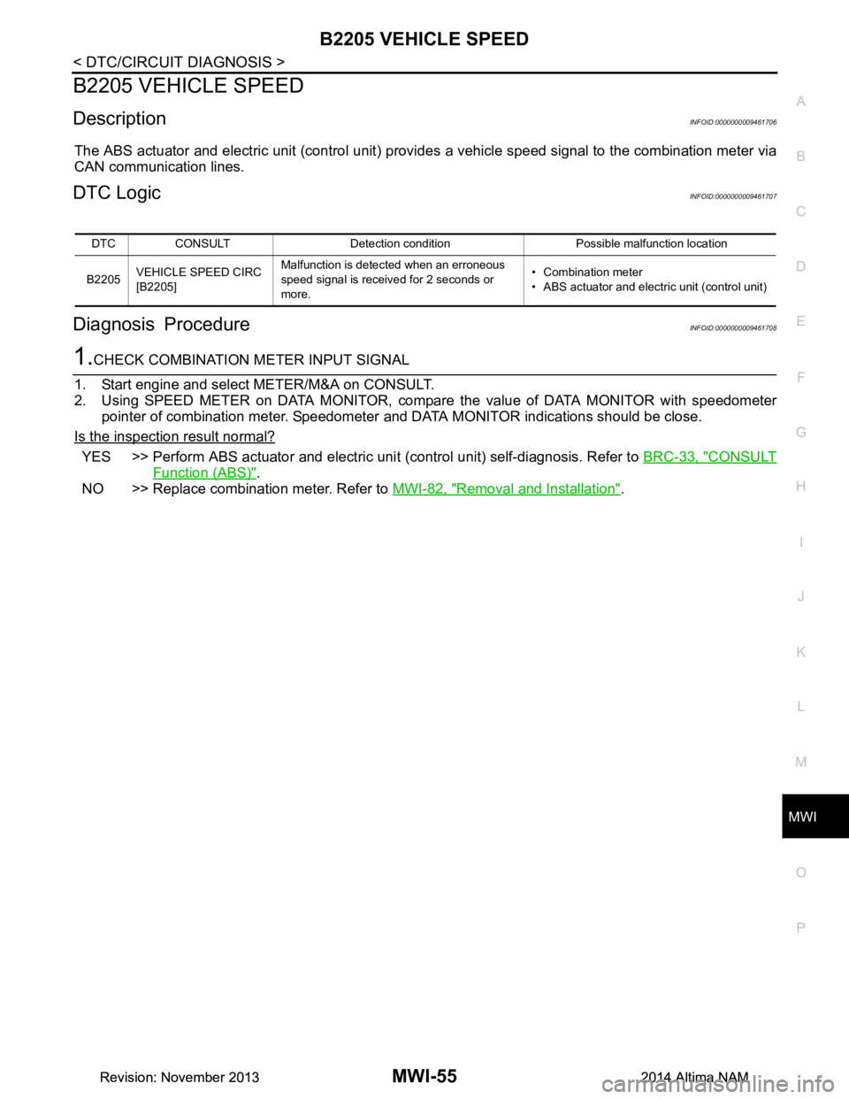
DescriptionINFOID:0000000009461706
The ABS actuator and electric unit (control unit) provi des a vehicle speed signal to the combination meter via
CAN communication lines.
DTC LogicINFOID:0000000009461707
Diagnosis ProcedureINFOID:0000000009461708
1.CHECK COMBINATION METER INPUT SIGNAL
1. Start engine and select METER/M&A on CONSULT.
2. Using SPEED METER on DATA MONITOR, compar e the value of DATA MONITOR with speedometer
pointer of combination meter. Speedometer and DATA MONITOR indications should be close.
Is the inspection result normal?
YES >> Perform ABS actuator and electric uni t (control unit) self-diagnosis. Refer to BRC-33, "CONSULT
Function (ABS)".
NO >> Replace combination meter. Refer to MWI-82, "Removal and Installation"
.
DTC CONSULT Detection condition Possible malfunction location
B2205 VEHICLE SPEED CIRC
[B2205] Malfunction is detected when an erroneous
speed signal is received for 2 seconds or
more. • Combination meter
• ABS actuator and electric unit (control unit)
Revision: November 20132014 Altima NAMRevision: November 20132014 Altima NAM
Page 3314 of 4801
MWI
POWER SUPPLY AND GROUND CIRCUITMWI-59
< DTC/CIRCUIT DIAGNOSIS >
C
D E
F
G H
I
J
K L
M B
A
O P
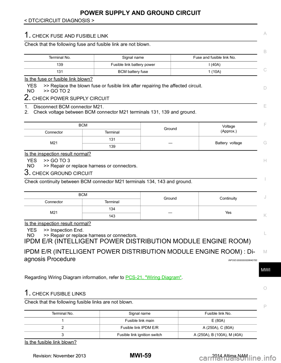
1. CHECK FUSE AND FUSIBLE LINK
Check that the following fuse and fusible link are not blown.
Is the fuse or fusible link blown?
YES >> Replace the blown fuse or fusible link after repairing the affected circuit.
NO >> GO TO 2
2. CHECK POWER SUPPLY CIRCUIT
1. Disconnect BCM connector M21.
2. Check voltage between BCM connector M21 terminals 131, 139 and ground.
Is the inspection result normal?
YES >> GO TO 3
NO >> Repair or replace harness or connectors.
3. CHECK GROUND CIRCUIT
Check continuity between BCM connector M21 terminals 134, 143 and ground.
Is the inspection result normal?
YES >> Inspection End.
NO >> Repair or replace harness or connectors.
IPDM E/R (INTELLIGENT POWER DIST RIBUTION MODULE ENGINE ROOM)
IPDM E/R (INTELLIGENT POWER DISTRIBUTION MODULE ENGINE ROOM) : Di-
agnosis Procedure
INFOID:0000000009940785
Regarding Wiring Diagram information, refer to PCS-21, "Wiring Diagram".
1. CHECK FUSIBLE LINKS
Check that the following fusible links are not blown.
Is the fusible link blown?
Terminal No. Signal name Fuse and fusible link No.
139 Fusible link battery power I (40A)
131 BCM battery fuse 1 (10A)
BCM GroundVo l ta g e
(Approx.)
Connector Terminal
M21 131
—Batteryvoltage
139
BCM Ground Continuity
Connector Terminal
M21 134
—Yes
143
Terminal No. Signal name Fusible link No.
1 Fusible link main E (80A)
2 Fusible link IPDM E/R A (250A), C (80A)
3 Fusible link ignition switch A (250A), B (100A), M (40A)
Revision: November 20132014 Altima NAMRevision: November 20132014 Altima NAM
Page 3318 of 4801
MWI
PARKING BRAKE SWITCH SIGNAL CIRCUITMWI-63
< DTC/CIRCUIT DIAGNOSIS >
C
D E
F
G H
I
J
K L
M B
A
O P
PARKING BRAKE SWITCH SIGNAL CIRCUIT
DescriptionINFOID:0000000009461722
Transmits the parking brake switch signal to the combination meter.
Component Function CheckINFOID:0000000009461723
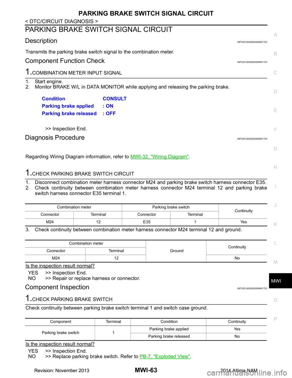
1.COMBINATION METER INPUT SIGNAL
1. Start engine.
2. Monitor BRAKE W/L in DATA MONITOR while applying and releasing the parking brake.
>> Inspection End.
Diagnosis ProcedureINFOID:0000000009461724
Regarding Wiring Diagram information, refer to MWI-32, "Wiring Diagram".
1.CHECK PARKING BRAKE SWITCH CIRCUIT
1. Disconnect combination meter harness connector M 24 and parking brake switch harness connector E35.
2. Check continuity between combination meter harness connector M24 terminal 12 and parking brake
switch harness connector E35 terminal 1.
3. Check continuity between combination meter harness connector M24 terminal 12 and ground.
Is the inspection result normal?
YES >> Inspection End.
NO >> Repair or replace harness or connector.
Component InspectionINFOID:0000000009461725
1.CHECK PARKING BRAKE SWITCH
Check continuity between parking brake s witch terminal 1 and switch case ground.
Is the inspection result normal?
YES >> Inspection End.
NO >> Replace parking brake switch. Refer to PB-7, "Exploded View"
.
Condition CONSULT
Parking brake applied : ON
Parking brake released : OFF
Combination meter Parking brake switch Continuity
Connector Terminal Connector Terminal
M24 12 E35 1 Yes
Combination meter GroundContinuity
Connector Terminal
M24 12 No
Component Terminal Condition Continuity
Parking brake switch 1 Parking brake applied Yes
Parking brake released No
Revision: November 20132014 Altima NAMRevision: November 20132014 Altima NAM
Page 3329 of 4801
MWI-74
< SYMPTOM DIAGNOSIS >
THE OIL PRESSURE WARNING CONTINUES DISPLAYING, OR DOES NOT DIS-
PLAY
THE OIL PRESSURE WARNING CONT INUES DISPLAYING, OR DOES
NOT DISPLAY
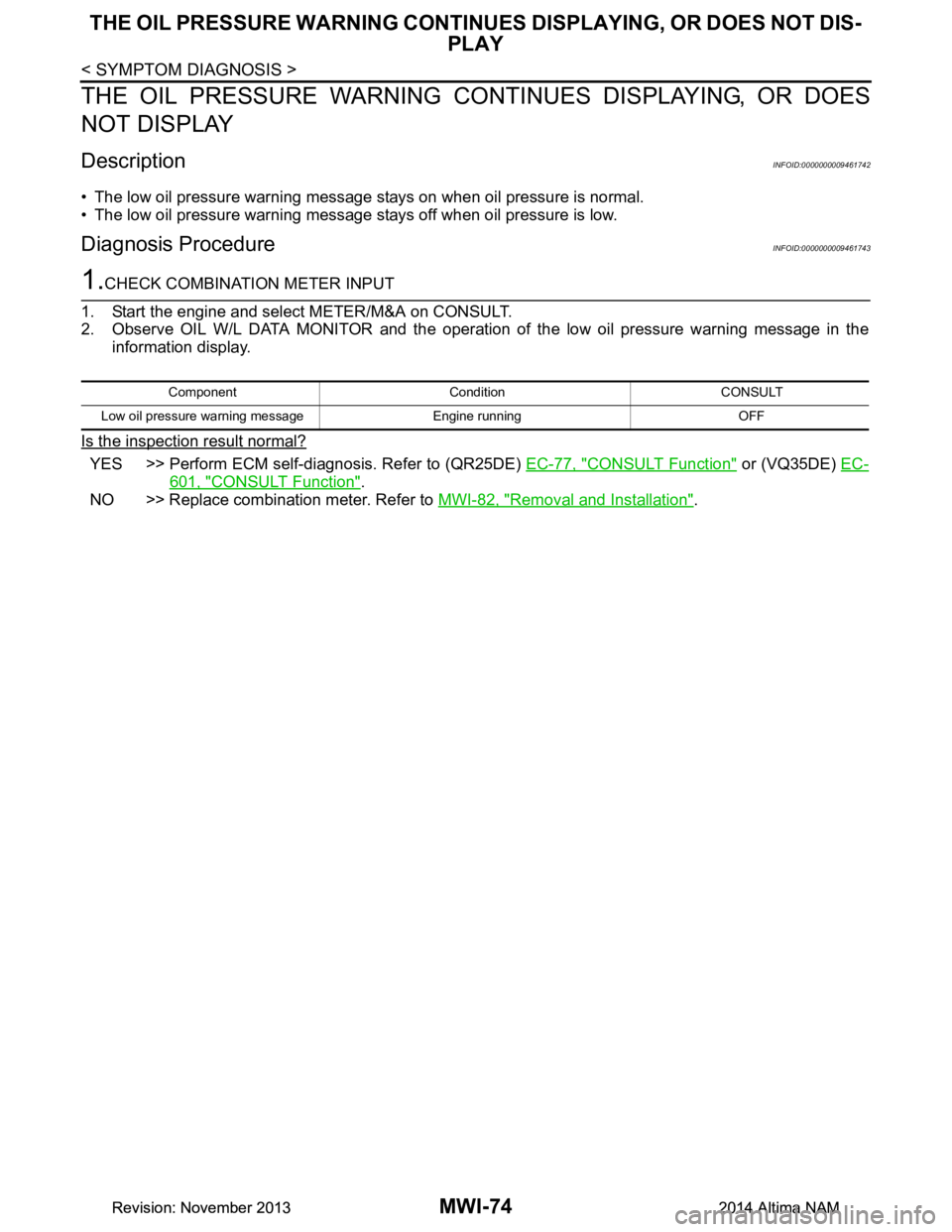
DescriptionINFOID:0000000009461742
• The low oil pressure warning message stays on when oil pressure is normal.
• The low oil pressure warning message stays off when oil pressure is low.
Diagnosis ProcedureINFOID:0000000009461743
1.CHECK COMBINATION METER INPUT
1. Start the engine and select METER/M&A on CONSULT.
2. Observe OIL W/L DATA MONITOR and the operation of the low oil pressure warning message in the
information display.
Is the inspection result normal?
YES >> Perform ECM self-diagnosis. Refer to (QR25DE) EC-77, "CONSULT Function" or (VQ35DE) EC-
601, "CONSULT Function".
NO >> Replace combination meter. Refer to MWI-82, "Removal and Installation"
.
Component Condi tion CONSULT
Low oil pressure warning message Engine running OFF
Revision: November 20132014 Altima NAMRevision: November 20132014 Altima NAM
Page 3330 of 4801
MWI
THE PARKING BRAKE RELEASE WARNING CONTINUES DISPLAYING, OR
DOES NOT DISPLAY
MWI-75
< SYMPTOM DIAGNOSIS >
C
D E
F
G H
I
J
K L
M B
A
O P
THE PARKING BRAKE RELEASE WA RNING CONTINUES DISPLAYING,
OR DOES NOT DISPLAY
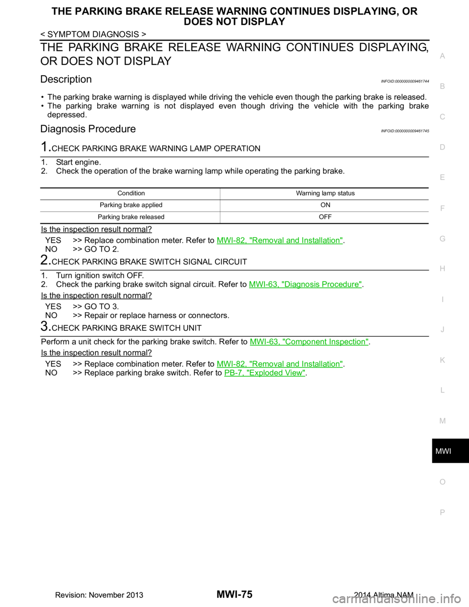
DescriptionINFOID:0000000009461744
• The parking brake warning is displayed while driving the vehicle even though the parking brake is released.
• The parking brake warning is not displayed even though driving the vehicle with the parking brake
depressed.
Diagnosis ProcedureINFOID:0000000009461745
1.CHECK PARKING BRAKE WARNING LAMP OPERATION
1. Start engine.
2. Check the operation of the brake warni ng lamp while operating the parking brake.
Is the inspection result normal?
YES >> Replace combination meter. Refer to MWI-82, "Removal and Installation".
NO >> GO TO 2.
2.CHECK PARKING BRAKE SWITCH SIGNAL CIRCUIT
1. Turn ignition switch OFF.
2. Check the parking brake switch signal circuit. Refer to MWI-63, "Diagnosis Procedure"
.
Is the inspection result normal?
YES >> GO TO 3.
NO >> Repair or replace harness or connectors.
3.CHECK PARKING BRAKE SWITCH UNIT
Perform a unit check for the parking brake switch. Refer to MWI-63, "Component Inspection"
.
Is the inspection result normal?
YES >> Replace combination meter. Refer to MWI-82, "Removal and Installation".
NO >> Replace parking brake switch. Refer to PB-7, "Exploded View"
.
Condition Warning lamp status
Parking brake applied ON
Parking brake released OFF
Revision: November 20132014 Altima NAMRevision: November 20132014 Altima NAM