Page 223 of 4801

C1115 ABS SENSOR [ABNORMAL SIGNAL]BRC-77
< DTC/CIRCUIT DIAGNOSIS > [VDC/TCS/ABS]
C
D E
G H
I
J
K L
M A
B
BRC
N
O P
YES >> GO TO 4.
NO >> Adjust tire pressure, or replace tire(s).
4.CHECK WIRING HARNESS FOR SHORT CIRCUIT
Check continuity between wheel sensor c onnector terminals and ground of wheel with DTC.
Is the inspection result normal?
YES >> GO TO 5.
NO >> Repair the circuit.
5.CHECK WIRING HARNESS FOR OPEN CIRCUIT
Check continuity between ABS actuat or and electric unit (control unit) connector E54 and wheel sensor con-
nector of wheel with DTC.
Is the inspection result normal?
YES >> Replace the ABS actuator and elec tric unit (control unit). Refer to BRC-128, "Removal and Instal-
lation".
NO >> Repair the circuit.
Wheel Sensor Ground Continuity
Wheel Connector Terminal
Front LH E19 1
—No
2
Front RH E41 1
2
Rear LH C2 1
2
Rear RH C3 1
2
Wheel sensor ABS actuator and electric
unit (control unit) W heel sensor Continuity
Connector Terminal Connector Terminal
Ye s
Front LH
E548
E19 2
19 1
Front RH 4
E41 2
16 1
Rear LH 18
C2 2
31 1
Rear RH 29
C3 2
17 1
Revision: November 20132014 Altima NAMRevision: November 20132014 Altima NAM
Page 224 of 4801

BRC-78
< DTC/CIRCUIT DIAGNOSIS >[VDC/TCS/ABS]
C1116 STOP LAMP SWITCH
C1116 STOP LAMP SWITCH
DTC LogicINFOID:0000000009463784
DTC DETECTION LOGIC
DTC CONFIRMATION PROCEDURE
1.CHECK SELF-DIAGNOSIS RESULTS
Check the self-diagnosis results.
Is above displayed on the self-diagnosis display?
YES >> Proceed to diagnosis procedure. Refer to BRC-78, "Diagnosis Procedure".
NO >> Inspection End.
Diagnosis ProcedureINFOID:0000000009463785
Regarding Wiring Diagram information, refer to BRC-47, "Wiring Diagram".
1.CONNECTOR INSPECTION
1. Disconnect stop lamp relay connector and ABS act uator and electric unit (control unit) connector.
2. Check terminals for deformation, disconnection, looseness or damage.
Is the inspection result normal?
YES >> GO TO 2.
NO >> Repair or replace as necessary.
2.CHECK STOP LAMP SWITCH CIRCUIT
1. Connect stop lamp relay connector.
2. Check voltage between ABS actuator and electric unit (control unit) connector E54 terminal 30 and
ground.
Is the inspection result normal?
YES >> Replace ABS actuator and electr ic unit (control unit). Refer to BRC-128, "Removal and Installa-
tion".
NO >> GO TO 3.
3.CHECK STOP LAMP RELAY CIRCUIT FOR OPEN
1. Disconnect stop lamp relay connector.
2. Check continuity between ABS actuator and electric unit (control unit) connector E54 terminal 30 and stop
lamp relay connector E57 terminal 3.
DTC Display item Malfunction detected condition Possible cause
C1116 STOP LAMP SW When stop lamp switch circuit is open. • Harness or connector
• Stop lamp switch
• ABS actuator and electric unit (control unit)
Self-diagnosis results
STOP LAMP SW
ABS actuator and electric unit (control unit) Ground ConditionVo l ta g e
(Approx.)
Connector Terminal
E54 30 — Brake pedal depressed Battery voltage
Brake pedal released 0V
Revision: November 20132014 Altima NAMRevision: November 20132014 Altima NAM
Page 227 of 4801
C1120, C1122, C1124, C1126 ABS IN VALVE SYSTEM
BRC-81
< DTC/CIRCUIT DIAGNOSIS > [VDC/TCS/ABS]
C
D E
G H
I
J
K L
M A
B
BRC
N
O P
Is the inspection result normal?
YES >> Replace ABS actuator and electric unit (control unit). Refer to BRC-128, "Removal and Installa-
tion".
NO >> Repair or replace malfunctioning components.
ABS actuator and electric unit (control unit) —Continuity
Connector Terminal
E54 13
Ground Yes
38
Revision: November 20132014 Altima NAMRevision: November 20132014 Altima NAM
Page 229 of 4801
C1121, C1123, C1125, C1127 ABS OUT VALVE SYSTEM
BRC-83
< DTC/CIRCUIT DIAGNOSIS > [VDC/TCS/ABS]
C
D E
G H
I
J
K L
M A
B
BRC
N
O P
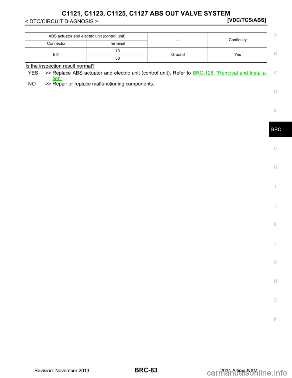
Is the inspection result normal?
YES >> Replace ABS actuator and electric unit (control unit). Refer to BRC-128, "Removal and Installa-
tion".
NO >> Repair or replace malfunctioning components.
ABS actuator and electric unit (control unit) —Continuity
Connector Terminal
E54 13
Ground Yes
38
Revision: November 20132014 Altima NAMRevision: November 20132014 Altima NAM
Page 230 of 4801

BRC-84
< DTC/CIRCUIT DIAGNOSIS >[VDC/TCS/ABS]
C1130 ENGINE SIGNAL
C1130 ENGINE SIGNAL
DTC LogicINFOID:0000000009463790
DTC DETECTION LOGIC
DTC CONFIRMATION PROCEDURE
1.CHECK SELF DIAGNOSTIC RESULT
With CONSULT.
1. Turn ignition switch ON.
2. Perform self diagnostic result.
Is DTC C1130 detected?
YES >> Proceed to diagnosis procedure. Refer to BRC-84, "Diagnosis Procedure".
NO >> Inspection End.
Diagnosis ProcedureINFOID:0000000009463791
1.CHECK SELF DIAGNOSTIC RESULT FOR ENGINE SYSTEM
With CONSULT.
Perform self diagnostic result. Refer to EC-77, "CONSULT Function"
(QR25DE) or EC-601, "CONSULT Func-
tion" (VQ35DE).
Are any ECM DTCs detected?
YES >> Refer to EC-105, "DTC Index" (QR25DE) or EC-630, "DTC Index" (VQ35DE).
NO >> GO TO 2.
2.CHECK SELF DIAGNOSTIC RESU LT FOR ABS ACTUATOR AND ELECTRIC UNIT (CONTROL UNIT)
With CONSULT.
1. Perform self diagnostic result and erase DTCs.
2. Turn ignition switch OFF.
3. Start engine and drive vehicle for a short period of time.
4. Check that malfunction indicator lamp (MIL) turns OFF.
5. Stop vehicle and perform self diagnostic result.
Is DTC C1130 detected?
YES >> Replace ABS actuator and electr ic unit (control unit). Refer to BRC-128, "Removal and Installa-
tion".
NO >> Check pin terminals and connection of connectors for abnormal conditions. Repair or replace mal- functioning components.
DTC Display Item Malfunction detected condition Possible causes
C1130 ENGINE SIGNAL 1 When a malfunction is detected in ECM system. •ECM
• ABS actuator and electric unit
(control unit)
• CAN communication line
Revision: November 20132014 Altima NAMRevision: November 20132014 Altima NAM
Page 232 of 4801
BRC-86
< DTC/CIRCUIT DIAGNOSIS >[VDC/TCS/ABS]
C1140 ACTUATOR RELAY SYSTEM
Is the inspection result normal?
YES >> Replace ABS actuator and electr
ic unit (control unit). Refer to BRC-128, "Removal and Installa-
tion".
NO >> Repair or replace malfunctioning components.
Revision: November 20132014 Altima NAMRevision: November 20132014 Altima NAM
Page 233 of 4801
C1142 PRESS SENSORBRC-87
< DTC/CIRCUIT DIAGNOSIS > [VDC/TCS/ABS]
C
D E
G H
I
J
K L
M A
B
BRC
N
O P
C1142 PRESS SENSOR
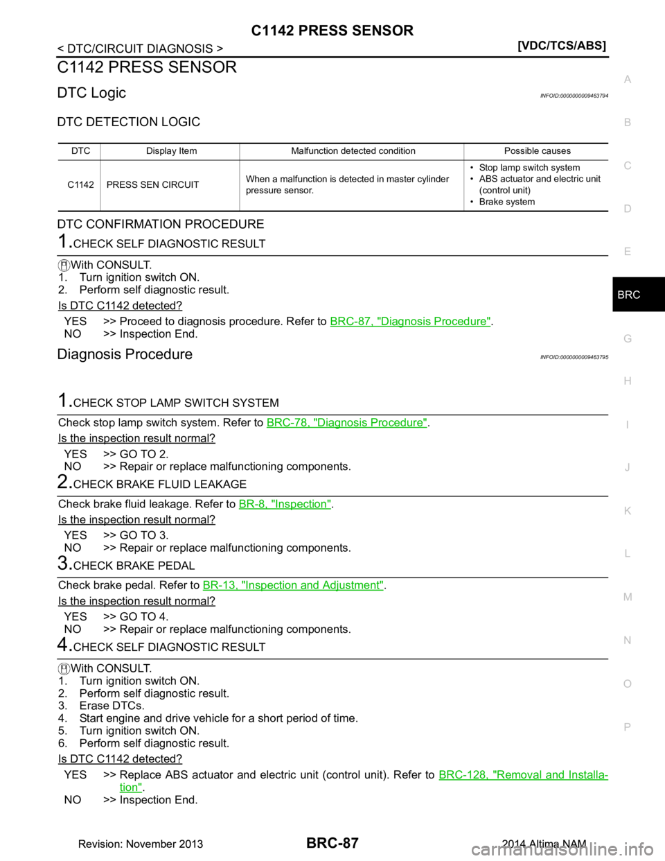
DTC LogicINFOID:0000000009463794
DTC DETECTION LOGIC
DTC CONFIRMATION PROCEDURE
1.CHECK SELF DIAGNOSTIC RESULT
With CONSULT.
1. Turn ignition switch ON.
2. Perform self diagnostic result.
Is DTC C1142 detected?
YES >> Proceed to diagnosis procedure. Refer to BRC-87, "Diagnosis Procedure".
NO >> Inspection End.
Diagnosis ProcedureINFOID:0000000009463795
1.CHECK STOP LAMP SWITCH SYSTEM
Check stop lamp switch system. Refer to BRC-78, "Diagnosis Procedure"
.
Is the inspection result normal?
YES >> GO TO 2.
NO >> Repair or replace malfunctioning components.
2.CHECK BRAKE FLUID LEAKAGE
Check brake fluid leakage. Refer to BR-8, "Inspection"
.
Is the inspection result normal?
YES >> GO TO 3.
NO >> Repair or replace malfunctioning components.
3.CHECK BRAKE PEDAL
Check brake pedal. Refer to BR-13, "Inspection and Adjustment"
.
Is the inspection result normal?
YES >> GO TO 4.
NO >> Repair or replace malfunctioning components.
4.CHECK SELF DIAGNOSTIC RESULT
With CONSULT.
1. Turn ignition switch ON.
2. Perform self diagnostic result.
3. Erase DTCs.
4. Start engine and drive vehicle for a short period of time.
5. Turn ignition switch ON.
6. Perform self diagnostic result.
Is DTC C1142 detected?
YES >> Replace ABS actuator and electric unit (control unit). Refer to BRC-128, "Removal and Installa-
tion".
NO >> Inspection End.
DTC Display Item Malfunction detected condition Possible causes
C1142 PRESS SEN CIRCUIT When a malfunction is detected in master cylinder
pressure sensor. • Stop lamp switch system
• ABS actuator and electric unit
(control unit)
• Brake system
Revision: November 20132014 Altima NAMRevision: November 20132014 Altima NAM
Page 235 of 4801

C1143 STEERING ANGLE SENSORBRC-89
< DTC/CIRCUIT DIAGNOSIS > [VDC/TCS/ABS]
C
D E
G H
I
J
K L
M A
B
BRC
N
O P
NO >> GO TO 4.
4.CHECK STEERING ANGLE SENSOR POWER SUPPLY CIRCUIT
1. Turn ignition switch OFF.
2. Disconnect IPDM E/R connector E63.
3. Check continuity between steering angle sensor c onnector M53 terminal 4 and IPDM E/R connector E63
terminal 19.
4. Check continuity between steering angle sensor connector M53 terminal 4 and ground.
Is the inspection result normal?
YES >> Perform trouble diagnosis for ignition power supply. Refer to PG-19, "Wiring Diagram — Ignition
Power Supply —".
NO >> Repair or replace malfunctioning components.
5.CHECK STEERING ANGLE SENSOR GROUND CIRCUIT
1. Turn ignition switch OFF.
2. Check continuity between steering angle sensor connector M53 terminal 1 and ground.
Is the inspection result normal?
YES >> GO TO 6.
NO >> Repair or replace malfunctioning components.
6.CHECK CAN COMMUNICATION LINE
Check “STRG BRANCH LINE CIRCUIT”. Refer to LAN-74, "Diagnosis Procedure"
(type 1) or LAN-90, "Diag-
nosis Procedure" (type 2).
Is the inspection result normal?
YES >> Replace ABS actuator and electric unit (control unit). Refer to BRC-128, "Removal and Installa-
tion".
NO >> Repair or replace malfunctioning components.
Steering angle sensor IPDM E/R Continuity
Connector Terminal Connector Terminal
M53 4 E63 19 Yes
Steering angle sensor —Continuity
Connector Terminal
M53 4 Ground No
Steering angle sensor —Continuity
Connector Terminal
M53 1 Ground Yes
Revision: November 20132014 Altima NAMRevision: November 20132014 Altima NAM