Page 2643 of 4801
COOLER PIPE AND HOSEHA-37
< REMOVAL AND INSTALLATION >
C
D E
F
G H
J
K L
M A
B
HA
N
O P
7. Remove the upper torque rod bolts (A).
8. Remove the upper torque rod (1).
9. Remove the bolt (A) that retains the high-pressure pipe to the expansion valve.
CAUTION:
Cap or wrap the joint of the pipe with a suitable material
such as vinyl tap to avo id the entry of air.
10. Remove the bolt (A) that retains the high-pressure pipe to the condenser pipe.
INSTALLATION
Installation is in the reverse order of removal.
CAUTION:
• Do not reuse O-rings.
• Apply A/C oil to new O-rings.
• After charging refrigerant, check for leaks. Refer to HA-21, "Leak Test"
.
ALIIA0620ZZ
ALIIA0629ZZ
ALIIA0630ZZ
Revision: November 20132014 Altima NAM
Page 2644 of 4801

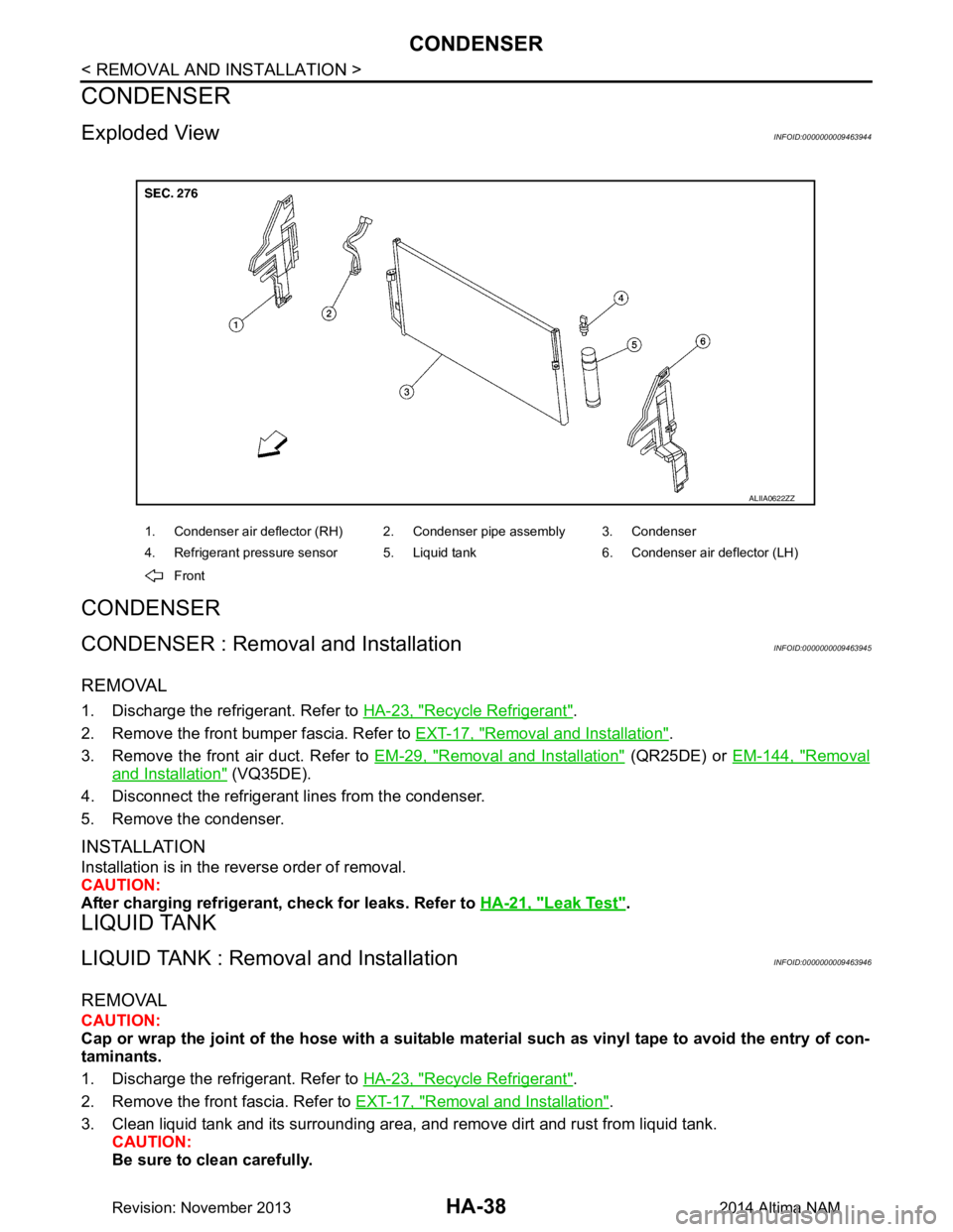
HA-38
< REMOVAL AND INSTALLATION >
CONDENSER
CONDENSER
Exploded ViewINFOID:0000000009463944
CONDENSER
CONDENSER : Removal and InstallationINFOID:0000000009463945
REMOVAL
1. Discharge the refrigerant. Refer to HA-23, "Recycle Refrigerant".
2. Remove the front bumper fascia. Refer to EXT-17, "Removal and Installation"
.
3. Remove the front air duct. Refer to EM-29, "Removal and Installation"
(QR25DE) or EM-144, "Removal
and Installation" (VQ35DE).
4. Disconnect the refrigerant lines from the condenser.
5. Remove the condenser.
INSTALLATION
Installation is in the reverse order of removal.
CAUTION:
After charging refrigerant, check for leaks. Refer to HA-21, "Leak Test"
.
LIQUID TANK
LIQUID TANK : Removal and InstallationINFOID:0000000009463946
REMOVAL
CAUTION:
Cap or wrap the joint of the hose with a suitable ma terial such as vinyl tape to avoid the entry of con-
taminants.
1. Discharge the refrigerant. Refer to HA-23, "Recycle Refrigerant"
.
2. Remove the front fascia. Refer to EXT-17, "Removal and Installation"
.
3. Clean liquid tank and its surrounding area, and remove dirt and rust from liquid tank. CAUTION:
Be sure to clean carefully.
1. Condenser air deflector (RH) 2. Condenser pipe assembly 3. Condenser
4. Refrigerant pressure sensor 5. Liquid tank 6. Condenser air deflector (LH)
Front
ALIIA0622ZZ
Revision: November 20132014 Altima NAM
Page 2645 of 4801

CONDENSERHA-39
< REMOVAL AND INSTALLATION >
C
D E
F
G H
J
K L
M A
B
HA
N
O P
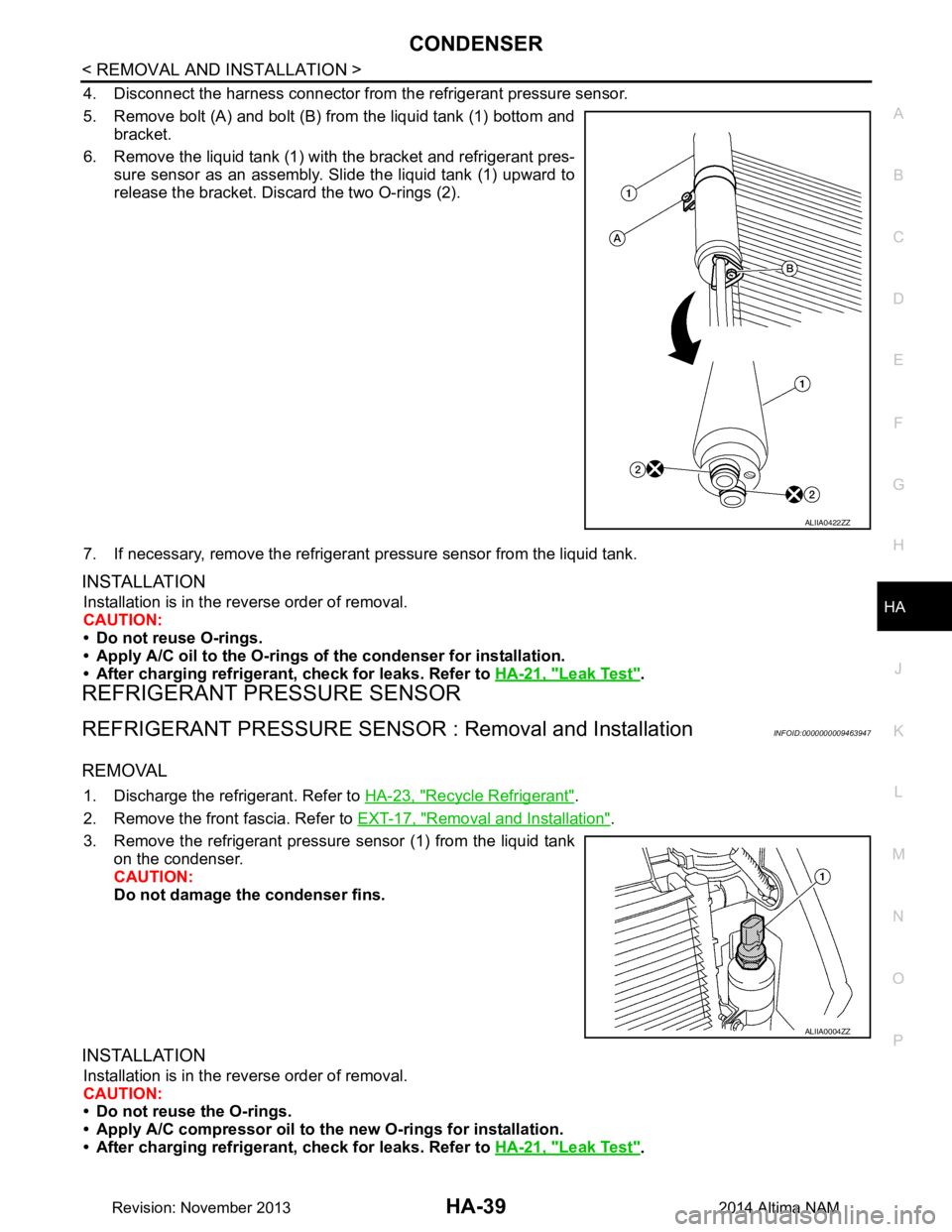
4. Disconnect the harness connector from the refrigerant pressure sensor.
5. Remove bolt (A) and bolt (B) from the liquid tank (1) bottom and bracket.
6. Remove the liquid tank (1) with the bracket and refrigerant pres-
sure sensor as an assembly. Slide the liquid tank (1) upward to
release the bracket. Discard the two O-rings (2).
7. If necessary, remove the refrigerant pressure sensor from the liquid tank.
INSTALLATION
Installation is in the reverse order of removal.
CAUTION:
• Do not reuse O-rings.
• Apply A/C oil to the O-rings of the condenser for installation.
• After charging refrigerant, check for leaks. Refer to HA-21, "Leak Test"
.
REFRIGERANT PRESSURE SENSOR
REFRIGERANT PRESSURE SENSOR : Removal and InstallationINFOID:0000000009463947
REMOVAL
1. Discharge the refrigerant. Refer to HA-23, "Recycle Refrigerant".
2. Remove the front fascia. Refer to EXT-17, "Removal and Installation"
.
3. Remove the refrigerant pressure sensor (1) from the liquid tank on the condenser.
CAUTION:
Do not damage the condenser fins.
INSTALLATION
Installation is in the reverse order of removal.
CAUTION:
• Do not reuse the O-rings.
• Apply A/C compressor oil to th e new O-rings for installation.
• After charging refrigerant, check for leaks. Refer to HA-21, "Leak Test"
.
ALIIA0422ZZ
ALIIA0004ZZ
Revision: November 20132014 Altima NAM
Page 2647 of 4801

HEATING AND COOLING UNIT ASSEMBLYHA-41
< REMOVAL AND INSTALLATION >
C
D E
F
G H
J
K L
M A
B
HA
N
O P
HEATING AND COOLING UNIT ASSEMB LY : Removal and InstallationINFOID:0000000009463949
REMOVAL
1. Discharge the refrigerant. Refer to HA-23, "Recycle Refrigerant".
2. Drain the cooling system. Refer to CO-12, "Changing Engine Coolant"
.
3. Remove the instrument panel assembly. Refer to IP-15, "Removal and Installation"
.
4. Remove the steering column. Refer to ST-33, "Removal and Installation"
.
5. Remove the strut tower brace. Refer to FSU-19, "Exploded View"
.
6. Disconnect the low-pressure pipe from the expansion valve. CAUTION:
Cap or wrap the joint of the pipe with suitable ma terial such as vinyl tape to avoid the entry of air.
7. Disconnect the high-pressure pi pe from the expansion valve.
8. Disconnect the heater hoses from the heater core pipes.
9. Remove the steering member cover (A) and bolt (B). NOTE:
The steering member cover (A) and bolt (B) can be found near
the cowl area in the engine compartment.
10. Remove the remaining steering member bolts.
11. Disconnect the harness connectors from the heati ng and cooling unit assembly and steering member.
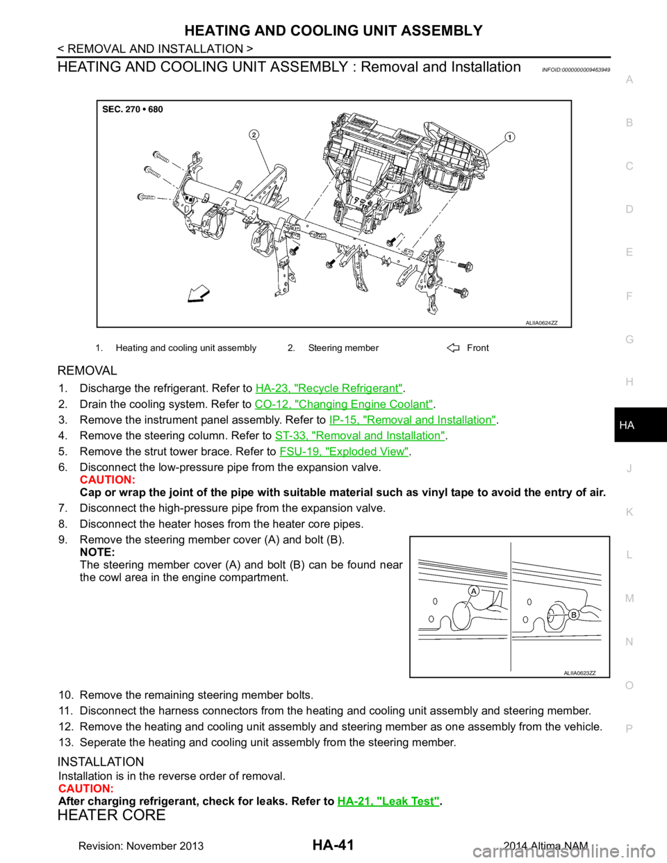
12. Remove the heating and cooling unit assembly and steering member as one assembly from the vehicle.
13. Seperate the heating and cooling unit assembly from the steering member.
INSTALLATION
Installation is in the reverse order of removal.
CAUTION:
After charging refrigerant, check for leaks. Refer to HA-21, "Leak Test"
.
HEATER CORE
1. Heating and cooling unit assembly 2. Steering member Front
ALIIA0624ZZ
ALIIA0623ZZ
Revision: November 20132014 Altima NAM
Page 2648 of 4801

HA-42
< REMOVAL AND INSTALLATION >
HEATING AND COOLING UNIT ASSEMBLY
HEATER CORE : Removal and Installation
INFOID:0000000009463950
REMOVAL
1. Remove the heating and cooling unit assembly. Refer to HA-41, "HEATING AND COOLING UNIT
ASSEMBLY : Removal and Installation".
2. Remove the heater core pipes cover. Refer to HA-40, "Exploded View"
.
3. Disconnect the harness connector from the blower motor.
4. Remove the heater core.
INSTALLATION
Installation is in the reverse order of removal.
EVAPORATOR
EVAPORATOR : Removal and InstallationINFOID:0000000009463951
REMOVAL
1. Remove the heater core. Refer to HA-42, "HEATER CORE : Removal and Installation".
2. Remove the upper floor connecting duct (RH). Refer to HA-40, "Exploded View"
.
3. Remove the air mix door motor (driver). Refer to HAC-109, "AIR MIX DOOR MOTOR : Removal and
Installation - Air Mix Door Motor (RH)".
4. Remove the air mix door motor (passenger) (if equipped). Refer to HAC-109, "AIR MIX DOOR MOTOR :
Removal and Installation - Air Mix Door Motor (LH)"
5. Disconnect the harness connector from the intake sensor.
6. Remove the evaporator and expansion valve assembly.
INSTALLATION
Installation is in the reverse order of removal.
NOTE:
The evaporator can only be ordered as an assembly with the expansion valve.
EXPANSION VALVE
EXPANSION VALVE : Removal and Installation for Expansion ValveINFOID:0000000009463952
REMOVAL
1. Discharge the refrigerant. Refer to HA-23, "Recycle Refrigerant".
2. Remove the strut tower brace. Refer to FSU-19, "Exploded View"
.
3. Disconnect the low-pressure pipe from the expansion valve.
4. Disconnect the high-pressure pipe from the expansion valve.
5. Remove the expansion valve bolts.
6. Remove the expansion valve.
INSTALLATION
Installation is in the reverse order of removal.
CAUTION:
After charging refrigerant, check for leaks. Refer to HA-21, "Leak Test"
.
Revision: November 20132014 Altima NAM
Page 2649 of 4801
SERVICE DATA AND SPECIFICATIONS (SDS)HA-43
< SERVICE DATA AND SPECIFICATIONS (SDS)
C
D E
F
G H
J
K L
M A
B
HA
N
O P
SERVICE DATA AND SPECIFICATIONS (SDS)
SERVICE DATA AND SPECIFICATIONS (SDS)
Service Data and Specification (SDS)INFOID:0000000009463953
COMPRESSOR
OIL
REFRIGERANT
Model VALEO
Type DCS-171C
Displacement 171 cm
3 (10.43 in3) / revolution
Direction of rotation Clockwise (viewed from drive end)
Drive belt QR25DE Poly V 6-grooves
VQ35DE Poly V 7-grooves
Name NISSAN A/C System Oil Type S or equivalent
Capacity Total in system
150 m (5.1 US fl oz, 5.3 lmp fl oz)
Compressor (service part) charging amount Refer to
HA-26, "Oil Adjusting Procedure for Compressor Re-
placement".
Type HFC-134a (R-134a)
Capacity 0.525 ± 0.025 kg (1.158 ± 0.055 lb)
Revision: November 20132014 Altima NAM
Page 2656 of 4801
PRECAUTIONSHAC-7
< PRECAUTION > [AUTOMATIC AIR CONDITIONER]
C
D E
F
G H
J
K L
M A
B
HAC
N
O P
Be certain that the service hoses display the markings described
(colored hose with black stripe). All hoses must include positive shut-
off devices (either manual or aut omatic) near the end of the hoses
opposite the manifold gauge.
SERVICE COUPLERS
Do not attempt to connect HFC-134a (R-134a) service couplers to a
CFC-12 (R-12) A/C system. T he HFC-134a (R-134a) couplers will
not properly connect to the CFC-12 (R-12) system. However, if an
improper connection is attempted, discharging and contamination
may occur.
RHA272D
Shut-off valve rotati on A/C service valve
Clockwise Open
Counterclockwise Close
RHA273D
Revision: November 20132014 Altima NAMRevision: November 20132014 Altima NAM
Page 2745 of 4801
![NISSAN TEANA 2014 Service Manual
HAC-96
< SYMPTOM DIAGNOSIS >[AUTOMATIC AIR CONDITIONER]
INSUFFICIENT COOLING
INSUFFICIENT COOLING
DescriptionINFOID:0000000009463167
Symptom
• Insufficient cooling
• No cool air comes out. (Air NISSAN TEANA 2014 Service Manual
HAC-96
< SYMPTOM DIAGNOSIS >[AUTOMATIC AIR CONDITIONER]
INSUFFICIENT COOLING
INSUFFICIENT COOLING
DescriptionINFOID:0000000009463167
Symptom
• Insufficient cooling
• No cool air comes out. (Air](/manual-img/5/57390/w960_57390-2744.png)
HAC-96
< SYMPTOM DIAGNOSIS >[AUTOMATIC AIR CONDITIONER]
INSUFFICIENT COOLING
INSUFFICIENT COOLING
DescriptionINFOID:0000000009463167
Symptom
• Insufficient cooling
• No cool air comes out. (Air flow volume is normal.)
Diagnosis ProcedureINFOID:0000000009463168
NOTE:
Perform self-diagnoses with CONSULT before performi ng symptom diagnosis. If any DTC is detected, per-
form the corresponding diagnosis.
1.CHECK MAGNET CLUTCH OPERATION
1. Turn ignition switch ON.
2. Operate fan switch.
3. Press A/C switch.
4. Check that A/C indicator turns ON. Check visually and by sound that compressor operates.
5. Press A/C switch again.
6. Check that A/C indicator turns OFF. Check that compressor stops.
Is the inspection result normal?
YES >> GO TO 2.
NO >> Perform diagnosis of “COMPRESSOR DOES NOT OPERATE” in “SYMPTOM DIAGNOSIS”.
Refer to HAC-99, "Diagnosis Procedure"
.
2.CHECK DRIVE BELT
Check tension of drive belt. Refer to EM-19, "Checking Drive Belts"
(QR25DE) or EM-134, "Checking Drive
Belts" (VQ35DE).
Is the inspection result normal?
YES >> GO TO 3.
NO >> Adjust or replace drive belt depending on the inspection results.
3.CHECK REFRIGERANT CYCLE
Connect recovery/recycling recharging equipment to the vehicle and perform pressure inspection with gauge.
Refer to HA-18, "Symptom Table"
.
Is the inspection result normal?
YES >> GO TO 4.
NO >> Repair or replace parts depending on the inspection results.
4.CHECK AIR LEAKAGE FROM EACH DUCT
Check duct and nozzle, etc. of the fr ont air conditioning system for leakage.
Is the inspection result normal?
YES >> GO TO 5.
NO >> Repair or replace parts depending on the inspection results.
5.CHECK AMBIENT TEMPERATURE DISPLAY
Check that there is not much difference between act ual ambient temperature and indicated temperature on
information display in combination meter.
Is the inspection result normal?
YES >> GO TO 6.
NO >> Perform diagnosis for the A/C auto amp. connection recognition signal circuit. Refer to HAC-60,
"Diagnosis Procedure".
6.CHECK SETTING OF TEMPERATURE SETTING TRIMMER (FRONT)
1. Check setting value of temperature setting trimmer (front). Refer to HAC-50, "Temperature Setting Trim-
mer".
2. Check that temperature setting trimme r (front) is set to “+ direction”.
Revision: November 20132014 Altima NAMRevision: November 20132014 Altima NAM