2014 NISSAN TEANA charging
[x] Cancel search: chargingPage 1508 of 4801
![NISSAN TEANA 2014 Service Manual
EC-508
< DTC/CIRCUIT DIAGNOSIS >[QR25DE]
FUEL PUMP
FUEL PUMP
DescriptionINFOID:0000000009462441
*: ECM determines the start signal status by the signals of engine speed and battery voltage.
The ECM a NISSAN TEANA 2014 Service Manual
EC-508
< DTC/CIRCUIT DIAGNOSIS >[QR25DE]
FUEL PUMP
FUEL PUMP
DescriptionINFOID:0000000009462441
*: ECM determines the start signal status by the signals of engine speed and battery voltage.
The ECM a](/manual-img/5/57390/w960_57390-1507.png)
EC-508
< DTC/CIRCUIT DIAGNOSIS >[QR25DE]
FUEL PUMP
FUEL PUMP
DescriptionINFOID:0000000009462441
*: ECM determines the start signal status by the signals of engine speed and battery voltage.
The ECM activates the fuel pump for several seconds after the ignition switch is turned ON to improve engine
start ability. If the ECM receives a engine speed signal from the camshaft position sensor (PHASE), it knows
that the engine is rotating, and causes the pump to operate. If the engine speed signal is not received when
the ignition switch is ON, the engine stalls. The EC M stops pump operation and prevents battery discharging,
thereby improving safety. The ECM does not directly driv e the fuel pump. It controls the ON/OFF fuel pump
relay, which in turn controls the fuel pump.
Component Function CheckINFOID:0000000009462442
1.CHECK FUEL PUMP FUNCTION
1. Turn ignition switch ON.
2. Pinch fuel feed hose with two fingers.
Is the inspection result normal?
YES >> INSPECTION END
NO >> Proceed to EC-508, "Diagnosis Procedure"
.
Diagnosis ProcedureINFOID:0000000009462443
1.CHECK FUEL PUMP RELAY CONTROL SIGNAL
1. Turn ignition switch ON.
2. Check the voltage between ECM harness connector.
*1: Except for California
*2: For California
Is the inspection result normal?
YES >> GO TO 3.
NO >> GO TO 2.
2.CHECK FUEL PUMP RELAY CONTROL SIGNAL CIRCUIT
1. Turn ignition switch OFF.
Sensor Input signal to ECM ECM Function Actuator
Crankshaft position sensor (POS)
Camshaft position sensor (PHASE) Engine speed*
Fuel pump controlFuel pump relay
↓
Fuel pump
Battery Battery voltage*
Condition Fuel pump operation
Ignition switch is turned to ON. Operates for 1 second.
Engine running and cranking Operates.
When engine is stopped Stops in 1.5 seconds.
Except as shown above Stops.
Fuel pressure pulsation should be felt on the fuel feed
hose for 1 second after igniti on switch is turned ON.
ECM
Vo l ta g e
+-
Connector Terminal Connector Terminal
F14
*1
F91*218 E10*1
E31*2128Battery voltage should exist 1 second after
ignition switch is turn ON.
Revision: November 20132014 Altima NAMRevision: November 20132014 Altima NAM
Page 1553 of 4801
![NISSAN TEANA 2014 Service Manual
COMPONENT PARTSEC-553
< SYSTEM DESCRIPTION > [VQ35DE]
C
D E
F
G H
I
J
K L
M A
EC
NP
O
A/F SENSOR 1 HEATER
A/F sensor 1 heater is integrated in the sensor.
The ECM performs ON/OFF duty control of th NISSAN TEANA 2014 Service Manual
COMPONENT PARTSEC-553
< SYSTEM DESCRIPTION > [VQ35DE]
C
D E
F
G H
I
J
K L
M A
EC
NP
O
A/F SENSOR 1 HEATER
A/F sensor 1 heater is integrated in the sensor.
The ECM performs ON/OFF duty control of th](/manual-img/5/57390/w960_57390-1552.png)
COMPONENT PARTSEC-553
< SYSTEM DESCRIPTION > [VQ35DE]
C
D E
F
G H
I
J
K L
M A
EC
NP
O
A/F SENSOR 1 HEATER
A/F sensor 1 heater is integrated in the sensor.
The ECM performs ON/OFF duty control of the A/F sensor 1 heater corresponding to the engine operating
condition to keep the temperature of A/F s ensor 1 element within the specified range.
ASCD Steering SwitchINFOID:0000000009462483
ASCD steering switch has variant values of electrical resistance for each button. ECM reads voltage variation
of switch, and determines which button is operated.
Battery Current Sensor (With Battery Temperature Sensor)INFOID:0000000009462484
OUTLINE
The power generation voltage variable control enables fuel con-
sumption to be decreased by reducing the engine load which is
caused by the power generation of the generator.
Based on sensor signals, ECM judges whether or not the power
generation voltage variable contro l is performed. When performing
the power generation voltage variable control, ECM calculates the
target power generation voltage based on the sensor signal. And
ECM sends the calculated value as the power generation command
value to IPDM E/R.
CAUTION:
Never connect the electrical componen t or the ground wire directly to the battery terminal. The con-
nection causes the malfunction of th e power generation voltage variable control, and then the battery
discharge may occur.
BATTERY CURRENT SENSOR
The battery current sensor is installed to the battery cable at the negative terminal. The sensor measures the
charging/discharging current of the battery.
BATTERY TEMPERATURE SENSOR
Battery temperature sensor is integrated in battery current sensor.
The sensor measures temperature around the battery.
The electrical resistance of the t hermistor decreases as temperature
increases.
*: These data are reference va lues and are measured between bat-
tery temperature sensor signal terminal and sensor ground.
JPBIA3262ZZ
Temperature [ °C ( °F)] Voltage* (V) Resistance (k Ω)
25 (77) 3.333 1.9 - 2.1
90 (194) 0.969 0.222 - 0.258
SEF012P
Revision: November 20132014 Altima NAMRevision: November 20132014 Altima NAM
Page 1558 of 4801
![NISSAN TEANA 2014 Service Manual
EC-558
< SYSTEM DESCRIPTION >[VQ35DE]
COMPONENT PARTS
EVAP Canister Vent Control Valve
INFOID:0000000009462496
The EVAP canister vent control valve is located on the EVAP canis-
ter and is used to s NISSAN TEANA 2014 Service Manual
EC-558
< SYSTEM DESCRIPTION >[VQ35DE]
COMPONENT PARTS
EVAP Canister Vent Control Valve
INFOID:0000000009462496
The EVAP canister vent control valve is located on the EVAP canis-
ter and is used to s](/manual-img/5/57390/w960_57390-1557.png)
EC-558
< SYSTEM DESCRIPTION >[VQ35DE]
COMPONENT PARTS
EVAP Canister Vent Control Valve
INFOID:0000000009462496
The EVAP canister vent control valve is located on the EVAP canis-
ter and is used to seal the canister vent.
This solenoid valve responds to signals from the ECM. When the
ECM sends an ON signal, the coil in the solenoid valve is energized.
A plunger will then move to seal the canister vent. The ability to seal
the vent is necessary for the on board diagnosis of other evaporative
emission control system components.
This solenoid valve is used only for diagnosis, and usually remains
opened.
When the vent is closed, under normal purge conditions, the evapo-
rative emission control system is depressurized and allows “EVAP
Control System” diagnosis.
EVAP Control System Pressure SensorINFOID:0000000009462497
The EVAP control system pressure s ensor detects pressure in the
purge line. The sensor output voltage to the ECM increases as pres-
sure increases.
Fuel InjectorINFOID:0000000009462498
The fuel injector is a small, precise solenoid valve. When the ECM
supplies a ground to the fuel injector circuit, the coil in the fuel injec-
tor is energized. The energized coil pulls the ball valve back and
allows fuel to flow through the fuel injector into the intake manifold.
The amount of fuel injected depends upon the injection pulse dura-
tion. Pulse duration is the length of time the fuel injector remains
open. The ECM controls the injection pulse duration based on
engine fuel needs.
Fuel Level Sensor Unit and Fuel Pump (With Fuel Tank Temperature Sensor)
INFOID:0000000009462499
FUEL PUMP
The ECM activates the fuel pump for 1 second after the ignition
switch is turned ON to improve engine start ability. If the ECM
receives a engine speed signal from the camshaft position sensor
(PHASE), it knows that the engine is rotating, and causes the pump
to operate. If the engine speed signal is not received when the igni-
tion switch is ON, the engine stalls. The ECM stops pump operation
and prevents battery discharging, thereby improving safety. The
ECM does not directly drive the fuel pump. It sends the control signal
to the fuel pump control module, which in turn controls the fuel
pump.
JSBIA1337GB
PBIB3370E
PBIA9664J
JSBIA1282ZZ
Revision: November 20132014 Altima NAMRevision: November 20132014 Altima NAM
Page 1587 of 4801
![NISSAN TEANA 2014 Service Manual
SYSTEMEC-587
< SYSTEM DESCRIPTION > [VQ35DE]
C
D E
F
G H
I
J
K L
M A
EC
NP
O
In the medium speed range, the ECM sends the ON si
gnal to the VIAS control solenoid valve. This signal
introduces the in NISSAN TEANA 2014 Service Manual
SYSTEMEC-587
< SYSTEM DESCRIPTION > [VQ35DE]
C
D E
F
G H
I
J
K L
M A
EC
NP
O
In the medium speed range, the ECM sends the ON si
gnal to the VIAS control solenoid valve. This signal
introduces the in](/manual-img/5/57390/w960_57390-1586.png)
SYSTEMEC-587
< SYSTEM DESCRIPTION > [VQ35DE]
C
D E
F
G H
I
J
K L
M A
EC
NP
O
In the medium speed range, the ECM sends the ON si
gnal to the VIAS control solenoid valve. This signal
introduces the intake manifold vacuum into the power valve actuator and therefore closes the power valve.
Under this condition, the pressure waves of the exhaust stroke do not disturb the pressure waves of the intake
stroke of each opposite bank. Therefore, charging efficiency is increased together with the effect of the long
intake passage.
However, in the high speed range, the ECM sends the OF F signal to the VIAS control solenoid valve and the
power valve is opened. Under this condition, the pressure waves of intake stroke are resonant with those of
each opposite bank exhaust stroke. Therefore, charging efficiency is also increased.
In addition, both valves 1 and 2 are opened or closed in other ranges mentioned above. Thus maximum
charging efficiency is obtained for the various driving conditions.
VACUUM HOSE DRAWING
INTEGRATED CONTROL OF ENGINE, CVT, AND ABS
1. Power valve actuator 1 2. VIAS control solenoid valve 1 3. VIAS control solenoid valve 2
4. Power valve actuator 2 5. Intake manifold collector
JMBIA0172ZZ
Revision: November 20132014 Altima NAMRevision: November 20132014 Altima NAM
Page 2612 of 4801

HA-6
< PRECAUTION >
PRECAUTIONS
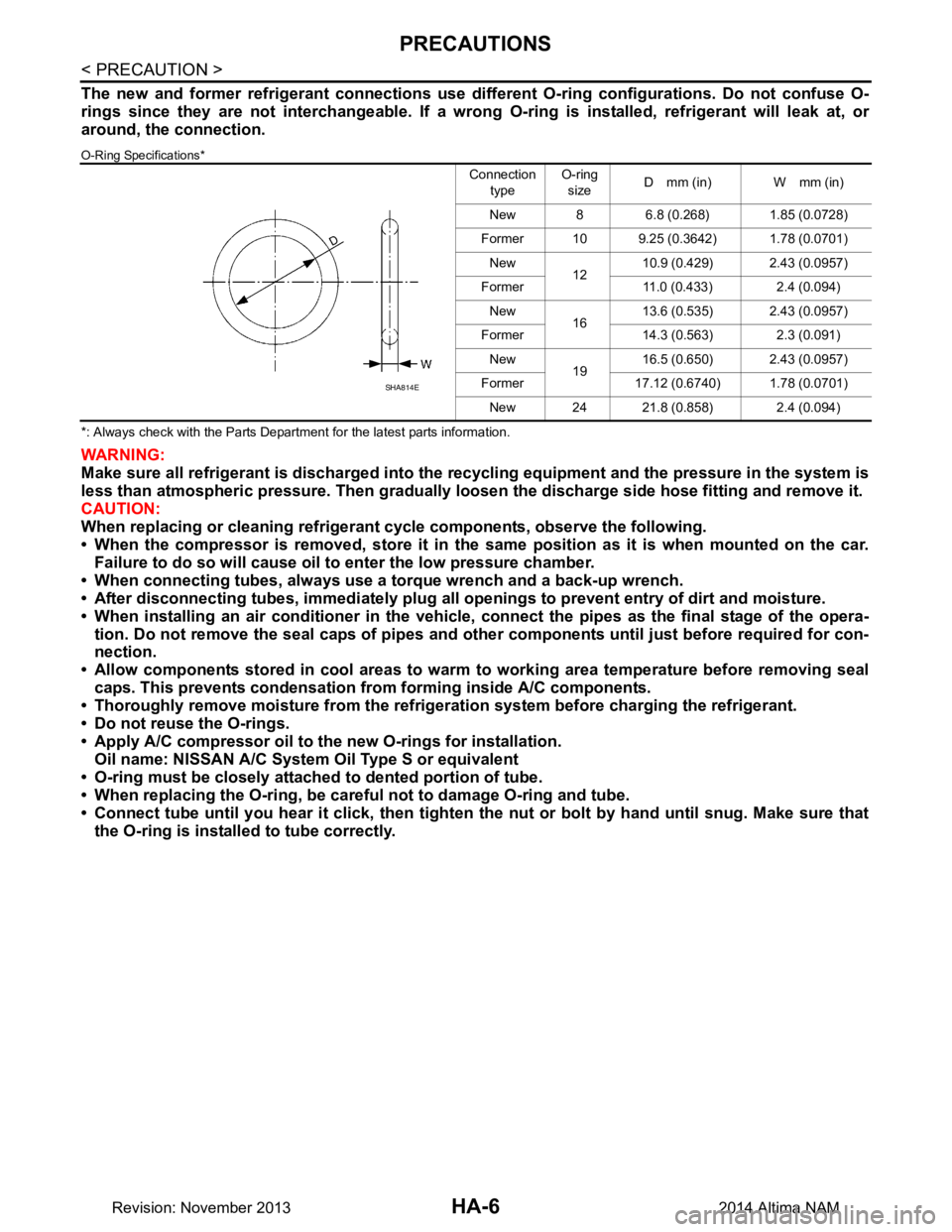
The new and former refrigerant connections use different O-ring configurations. Do not confuse O-
rings since they are not interchangeable. If a wrong O-ring is installed, refrigerant will leak at, or
around, the connection.
O-Ring Specifications*
*: Always check with the Parts Department for the latest parts information.
WARNING:
Make sure all refrigerant is discharged into the recycling equipment and the pressure in the system is
less than atmospheric pressure. Then gradually loo sen the discharge side hose fitting and remove it.
CAUTION:
When replacing or cleaning refrigeran t cycle components, observe the following.
• When the compressor is removed, store it in the same position as it is when mounted on the car.
Failure to do so will cause oil to enter the low pressure chamber.
• When connecting tubes, always use a torque wrench and a back-up wrench.
• After disconnecting tubes, immedi ately plug all openings to prevent entry of dirt and moisture.
• When installing an air conditioner in the vehicle, connect the pipes as the final stage of the opera-
tion. Do not remove the seal caps of pipes and othe r components until just before required for con-
nection.
• Allow components stored in cool areas to warm to working area temperature before removing seal
caps. This prevents condensation from forming inside A/C components.
• Thoroughly remove moisture from the refrigerat ion system before charging the refrigerant.
• Do not reuse the O-rings.
• Apply A/C compressor oil to th e new O-rings for installation.
Oil name: NISSAN A/C System Oil Type S or equivalent
• O-ring must be closely attached to dented portion of tube.
• When replacing the O-ring, be careful not to damage O-ring and tube.
• Connect tube until you hear it cl ick, then tighten the nut or bolt by hand until snug. Make sure that
the O-ring is installed to tube correctly.
Connection
type O-ring
size D mm (in) W mm (in)
New 8 6.8 (0.268) 1.85 (0.0728)
Former 10 9.25 (0.3642) 1.78 (0.0701) New 1210.9 (0.429) 2.43 (0.0957)
Former 11.0 (0.433) 2.4 (0.094) New 1613.6 (0.535) 2.43 (0.0957)
Former 14.3 (0.563) 2.3 (0.091) New 1916.5 (0.650) 2.43 (0.0957)
Former 17.12 (0.6740) 1.78 (0.0701) New 24 21.8 (0.858) 2.4 (0.094)
SHA814E
Revision: November 20132014 Altima NAM
Page 2614 of 4801

HA-8
< PRECAUTION >
PRECAUTIONS
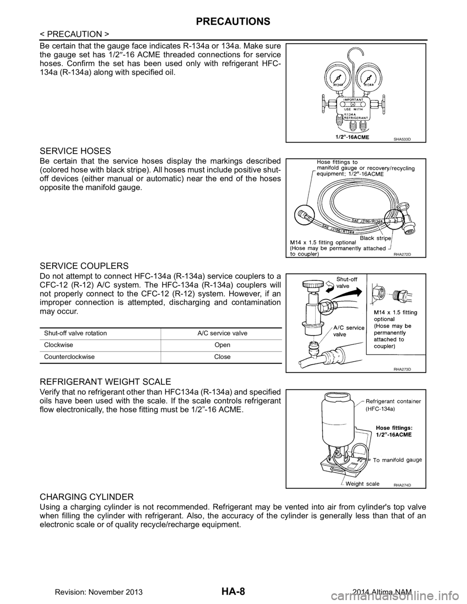
Be certain that the gauge face indicates R-134a or 134a. Make sure
the gauge set has 1/2 ″-16 ACME threaded connections for service
hoses. Confirm the set has been used only with refrigerant HFC-
134a (R-134a) along with specified oil.
SERVICE HOSES
Be certain that the service hoses display the markings described
(colored hose with black stripe). All hoses must include positive shut-
off devices (either manual or aut omatic) near the end of the hoses
opposite the manifold gauge.
SERVICE COUPLERS
Do not attempt to connect HFC-134a (R-134a) service couplers to a
CFC-12 (R-12) A/C system. The HFC-134a (R-134a) couplers will
not properly connect to the CFC-12 (R-12) system. However, if an
improper connection is attempted, discharging and contamination
may occur.
REFRIGERANT WEIGHT SCALE
Verify that no refrigerant other than HFC134a (R-134a) and specified
oils have been used with the scale. If the scale controls refrigerant
flow electronically, the hose fitting must be 1/2”-16 ACME.
CHARGING CYLINDER
Using a charging cylinder is not recommended. Refrigerant may be vented into air from cylinder's top valve
when filling the cylinder with refrigerant. Also, the accu racy of the cylinder is generally less than that of an
electronic scale or of quality recycle/recharge equipment.
SHA533D
RHA272D
Shut-off valve rotati on A/C service valve
Clockwise Open
Counterclockwise Close
RHA273D
RHA274D
Revision: November 20132014 Altima NAM
Page 2616 of 4801

HA-10
< PREPARATION >
PREPARATION
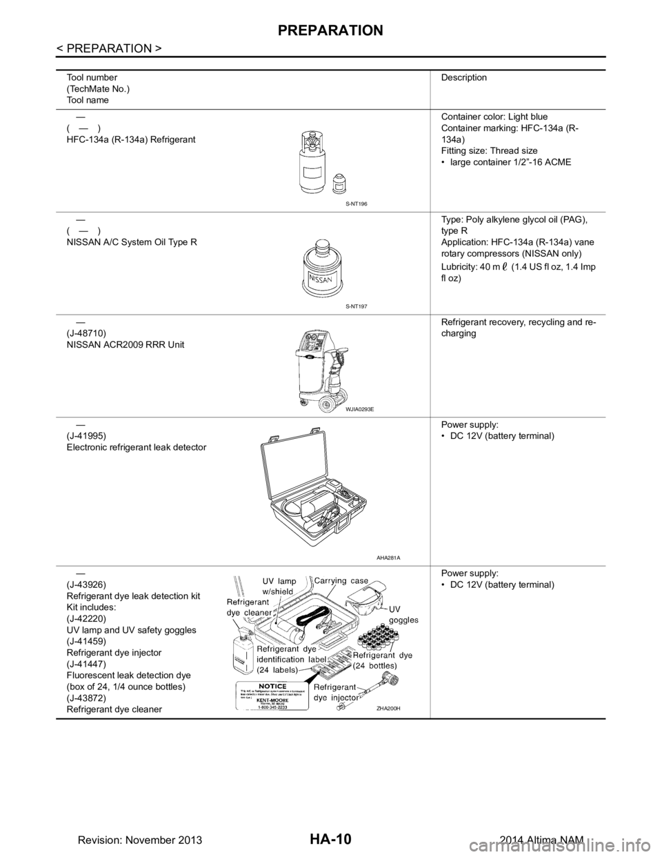
Tool number
(TechMate No.)
Tool name Description
—
(—)
HFC-134a (R-134a) Refrigerant Container color: Light blue
Container marking: HFC-134a (R-
134a)
Fitting size: Thread size
• large container 1/2”-16 ACME
—
(—)
NISSAN A/C System Oil Type R Type: Poly alkylene glycol oil (PAG),
type R
Application: HFC-134a (R-134a) vane
rotary compressors (NISSAN only)
Lubricity: 40 m (1.4 US fl oz, 1.4 Imp
fl oz)
—
(J-48710)
NISSAN ACR2009 RRR Unit Refrigerant recovery, recycling and re-
charging
—
(J-41995)
Electronic refrigerant leak detector Power supply:
• DC 12V (batte ry terminal)
—
(J-43926)
Refrigerant dye leak detection kit
Kit includes:
(J-42220)
UV lamp and UV safety goggles
(J-41459)
Refrigerant dye injector
(J-41447)
Fluorescent leak detection dye
(box of 24, 1/4 ounce bottles)
(J-43872)
Refrigerant dye cleaner Power supply:
• DC 12V (batte ry terminal)
S-NT196
S-NT197
WJIA0293E
AHA281A
ZHA200H
Revision: November 20132014 Altima NAM
Page 2627 of 4801

REFRIGERANTHA-21
< PERIODIC MAINTENANCE >
C
D E
F
G H
J
K L
M A
B
HA
N
O P
PERIODIC MAINTENANCE
REFRIGERANT
DescriptionINFOID:0000000009463926
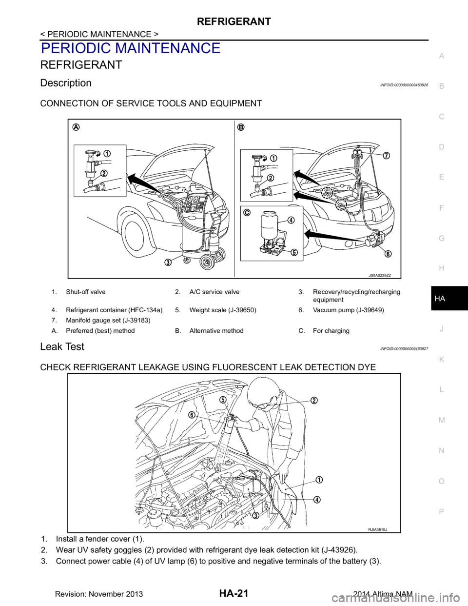
CONNECTION OF SERVICE TOOLS AND EQUIPMENT
Leak TestINFOID:0000000009463927
CHECK REFRIGERANT LEAKAGE USING FLUORESCENT LEAK DETECTION DYE
1. Install a fender cover (1).
2. Wear UV safety goggles (2) provided with refrigerant dye leak detection kit (J-43926).
3. Connect power cable (4) of UV lamp (6) to positive and negative terminals of the battery (3).
1. Shut-off valve 2. A/C service valve 3. Recovery/recycling/recharging
equipment
4. Refrigerant container (HFC-134a) 5. Weight scale (J-39650) 6. Vacuum pump (J-39649)
7. Manifold gauge set (J-39183)
A. Preferred (best) method B. Alternative method C. For charging
JSIIA0239ZZ
RJIA3815J
Revision: November 20132014 Altima NAM