2014 NISSAN TEANA charging
[x] Cancel search: chargingPage 2756 of 4801
![NISSAN TEANA 2014 Service Manual
REFRIGERANT PRESSURE SENSORHAC-107
< REMOVAL AND INSTALLATION > [AUTOMATIC AIR CONDITIONER]
C
D E
F
G H
J
K L
M A
B
HAC
N
O P
REFRIGERANT PRESSURE SENSOR
Removal and InstallationINFOID:000000000946 NISSAN TEANA 2014 Service Manual
REFRIGERANT PRESSURE SENSORHAC-107
< REMOVAL AND INSTALLATION > [AUTOMATIC AIR CONDITIONER]
C
D E
F
G H
J
K L
M A
B
HAC
N
O P
REFRIGERANT PRESSURE SENSOR
Removal and InstallationINFOID:000000000946](/manual-img/5/57390/w960_57390-2755.png)
REFRIGERANT PRESSURE SENSORHAC-107
< REMOVAL AND INSTALLATION > [AUTOMATIC AIR CONDITIONER]
C
D E
F
G H
J
K L
M A
B
HAC
N
O P
REFRIGERANT PRESSURE SENSOR
Removal and InstallationINFOID:0000000009463180
REMOVAL
1. Discharge the refrigerant. Refer to HA-23, "Recycle Refrigerant".
2. Remove the front bumper fascia. Refer to EXT-17, "Removal and Installation"
.
3. Disconnect the harness connector from the refrigerant pressure sensor.
4. Remove the refrigerant pressure sensor. CAUTION:
Cap or wrap the opening of the refrigerant pressu re sensor with suitable material such as vinyl
tape to avoid the entry of air.
INSTALLATION
Installation is in the reverse order of removal.
CAUTION:
• Do not reuse O-ring.
• Apply A/C oil to the O-ri ng of the refrigerant pressu re sensor for installation.
• After charging refrigerant, check for leaks. Refer to HA-21, "Leak Test"
.
Revision: November 20132014 Altima NAMRevision: November 20132014 Altima NAM
Page 2761 of 4801
![NISSAN TEANA 2014 Service Manual
HAC-112
< PRECAUTION >[MANUAL AIR CONDITIONER]
PRECAUTIONS
Be certain that the service hoses display the markings described
(colored hose with black stripe). All hoses must include positive shut-
o NISSAN TEANA 2014 Service Manual
HAC-112
< PRECAUTION >[MANUAL AIR CONDITIONER]
PRECAUTIONS
Be certain that the service hoses display the markings described
(colored hose with black stripe). All hoses must include positive shut-
o](/manual-img/5/57390/w960_57390-2760.png)
HAC-112
< PRECAUTION >[MANUAL AIR CONDITIONER]
PRECAUTIONS
Be certain that the service hoses display the markings described
(colored hose with black stripe). All hoses must include positive shut-
off devices (either manual or aut omatic) near the end of the hoses
opposite the manifold gauge.
SERVICE COUPLERS
Do not attempt to connect HFC-134a (R-134a) service couplers to a
CFC-12 (R-12) A/C system. The HFC-134a (R-134a) couplers will
not properly connect to the CFC-12 (R-12) system. However, if an
improper connection is attempted, discharging and contamination
may occur.
RHA272D
Shut-off valve rotati on A/C service valve
Clockwise Open
Counterclockwise Close
RHA273D
Revision: November 20132014 Altima NAMRevision: November 20132014 Altima NAM
Page 2812 of 4801
![NISSAN TEANA 2014 Service Manual
REFRIGERANT PRESSURE SENSORHAC-163
< REMOVAL AND INSTALLATION > [MANUAL AIR CONDITIONER]
C
D E
F
G H
J
K L
M A
B
HAC
N
O P
REFRIGERANT PRESSURE SENSOR
Removal and InstallationINFOID:000000000946322 NISSAN TEANA 2014 Service Manual
REFRIGERANT PRESSURE SENSORHAC-163
< REMOVAL AND INSTALLATION > [MANUAL AIR CONDITIONER]
C
D E
F
G H
J
K L
M A
B
HAC
N
O P
REFRIGERANT PRESSURE SENSOR
Removal and InstallationINFOID:000000000946322](/manual-img/5/57390/w960_57390-2811.png)
REFRIGERANT PRESSURE SENSORHAC-163
< REMOVAL AND INSTALLATION > [MANUAL AIR CONDITIONER]
C
D E
F
G H
J
K L
M A
B
HAC
N
O P
REFRIGERANT PRESSURE SENSOR
Removal and InstallationINFOID:0000000009463229
REMOVAL
1. Discharge the refrigerant. Refer to HA-23, "Recycle Refrigerant".
2. Remove the front bumper fascia. Refer to EXT-17, "Removal and Installation"
.
3. Disconnect the harness connector from the refrigerant pressure sensor.
4. Remove the refrigerant pressure sensor. CAUTION:
Cap or wrap the opening of the refrigerant pressu re sensor with suitable material such as vinyl
tape to avoid the entry of air.
INSTALLATION
Installation is in the reverse order of removal.
CAUTION:
• Do not reuse O-ring.
• Apply A/C oil to the O-ri ng of the refrigerant pressu re sensor for installation.
• After charging refrigerant, check for leaks. Refer to HA-21, "Leak Test"
.
Revision: November 20132014 Altima NAMRevision: November 20132014 Altima NAM
Page 3217 of 4801

CHASSIS AND BODY MAINTENANCEMA-33
< PERIODIC MAINTENANCE >
C
D E
F
G H
I
J
K L
M B
MA
N
O A
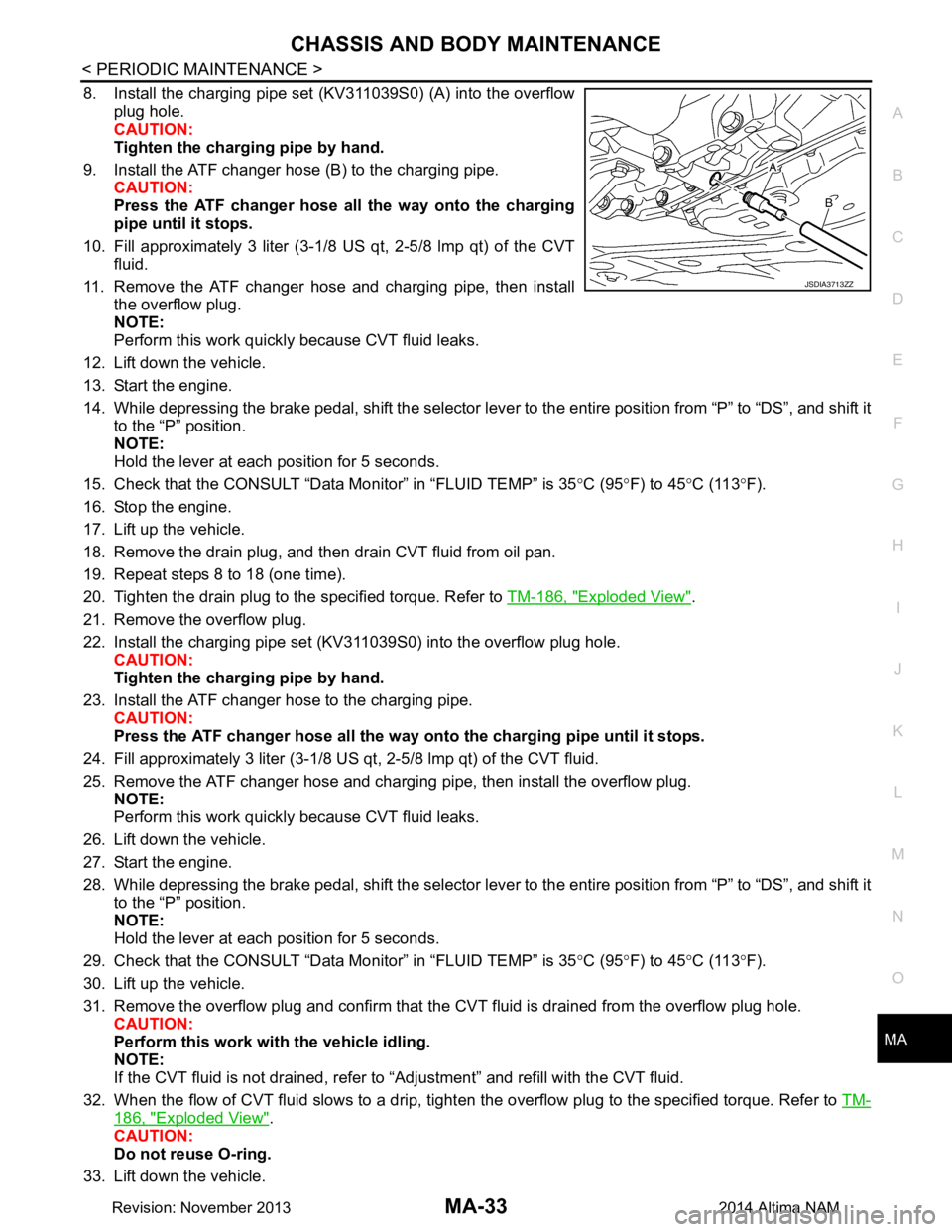
8. Install the charging pipe set (KV311039S0) (A) into the overflow
plug hole.
CAUTION:
Tighten the charging pipe by hand.
9. Install the ATF changer hose (B) to the charging pipe. CAUTION:
Press the ATF changer hose all the way onto the charging
pipe until it stops.
10. Fill approximately 3 liter (3-1/8 US qt, 2-5/8 lmp qt) of the CVT fluid.
11. Remove the ATF changer hose and charging pipe, then install the overflow plug.
NOTE:
Perform this work quickly because CVT fluid leaks.
12. Lift down the vehicle.
13. Start the engine.
14. While depressing the brake pedal, shift the selector leve r to the entire position from “P” to “DS”, and shift it
to the “P” position.
NOTE:
Hold the lever at each position for 5 seconds.
15. Check that the CONSULT “Data Monitor” in “FLUID TEMP” is 35°C (95 °F) to 45 °C (113 °F).
16. Stop the engine.
17. Lift up the vehicle.
18. Remove the drain plug, and then drain CVT fluid from oil pan.
19. Repeat steps 8 to 18 (one time).
20. Tighten the drain plug to the specified torque. Refer to TM-186, "Exploded View"
.
21. Remove the overflow plug.
22. Install the charging pipe set (KV311039S0) into the overflow plug hole. CAUTION:
Tighten the charging pipe by hand.
23. Install the ATF changer hose to the charging pipe. CAUTION:
Press the ATF changer hose all the way onto the charging pipe until it stops.
24. Fill approximately 3 liter (3-1/8 US qt, 2-5/8 lmp qt) of the CVT fluid.
25. Remove the ATF changer hose and charging pipe, then install the overflow plug. NOTE:
Perform this work quickly because CVT fluid leaks.
26. Lift down the vehicle.
27. Start the engine.
28. While depressing the brake pedal, shift the selector leve r to the entire position from “P” to “DS”, and shift it
to the “P” position.
NOTE:
Hold the lever at each position for 5 seconds.
29. Check that the CONSULT “Data Monitor” in “FLUID TEMP” is 35°C (95 °F) to 45 °C (113 °F).
30. Lift up the vehicle.
31. Remove the overflow plug and confirm that the CV T fluid is drained from the overflow plug hole.
CAUTION:
Perform this work with the vehicle idling.
NOTE:
If the CVT fluid is not drained, refer to “Adjustment” and refill with the CVT fluid.
32. When the flow of CVT fluid slows to a drip, tighten the overflow plug to the specified torque. Refer to TM-
186, "Exploded View".
CAUTION:
Do not reuse O-ring.
33. Lift down the vehicle.
JSDIA3713ZZ
Revision: November 20132014 Altima NAM
Page 3218 of 4801

MA-34
< PERIODIC MAINTENANCE >
CHASSIS AND BODY MAINTENANCE
34. Select “Data Monitor” in “TRANSMISSION” using CONSULT.
35. Select “CONFORM CVTF DETERIORTN”.
36. Select “Erase”.
37. Stop the engine.
CVT FLUID : AdjustmentINFOID:0000000009464569
CAUTION:
• During adjustment of the CVT fluid level, check CO NSULT so that the oil temperature may be main-
tained from 35 to 45 °C (95 to 113 °F).
• During adjustment of the CVT fluid level, check that the engine speed is maintaining 500 rpm.
• Use caution when looking into the drain hole as th ere is a risk of dripping fluid entering the eye.
1. Check that the selector lever is in the “P ” position, then completely engage the parking brake.
2. Start the engine.
3. Adjust the CVT fluid temperature to be approximately 40 °C (104 °F).
NOTE:
The CVT fluid is largely affected by temperature. Therefore be sure to use CONSULT and check the
“FLUID TEMP” under “TRANSMISSION” in “Data Monitor” while adjusting.
4. While depressing the brake pedal, shift the selector lever to the entire position from “P” to “DS”, and shift it to the “P” position.
NOTE:
Hold the lever at each position for 5 seconds.
5. Lift up the vehicle.
6. Check that there is no CVT fluid leakage.
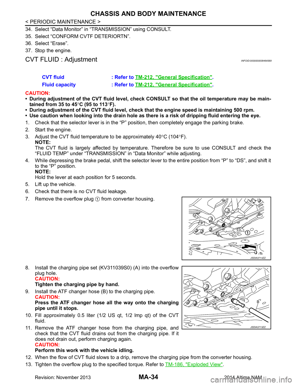
7. Remove the overflow plug from converter housing.
8. Install the charging pipe set (KV311039S0) (A) into the overflow plug hole.
CAUTION:
Tighten the charging pipe by hand.
9. Install the ATF changer hose (B) to the charging pipe. CAUTION:
Press the ATF changer hose all the way onto the charging
pipe until it stops.
10. Fill approximately 0.5 liter (1/2 US qt, 1/2 lmp qt) of the CVT
fluid.
11. Remove the ATF changer hose from the charging pipe, and check that the CVT fluid drains out from the charging pipe. If it
does not drain out, perform charging again.
CAUTION:
Perform this work with the vehicle idling.
12. When the flow of CVT fluid slows to a drip, re move the charging pipe from the converter housing.
13. Tighten the overflow plug to the specified torque. Refer to TM-186, "Exploded View"
.
CVT fluid : Refer to
TM-212, "General Specification"
.
Fluid capacity : Refer to TM-212, "General Specification"
.
JSDIA3714ZZ
JSDIA3713ZZ
Revision: November 20132014 Altima NAM
Page 3220 of 4801

MA-36
< PERIODIC MAINTENANCE >
CHASSIS AND BODY MAINTENANCE
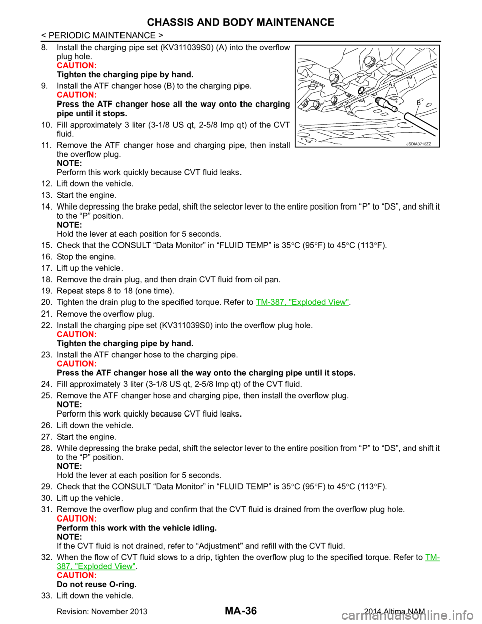
8. Install the charging pipe set (KV311039S0) (A) into the overflowplug hole.
CAUTION:
Tighten the charging pipe by hand.
9. Install the ATF changer hose (B) to the charging pipe. CAUTION:
Press the ATF changer hose all the way onto the charging
pipe until it stops.
10. Fill approximately 3 liter (3-1/8 US qt, 2-5/8 lmp qt) of the CVT
fluid.
11. Remove the ATF changer hose and charging pipe, then install the overflow plug.
NOTE:
Perform this work quickly because CVT fluid leaks.
12. Lift down the vehicle.
13. Start the engine.
14. While depressing the brake pedal, shift the selector lever to the entire position from “P” to “DS”, and shift it to the “P” position.
NOTE:
Hold the lever at each position for 5 seconds.
15. Check that the CONSULT “Data Monitor” in “FLUID TEMP” is 35 °C (95 °F) to 45 °C (113 °F).
16. Stop the engine.
17. Lift up the vehicle.
18. Remove the drain plug, and then drain CVT fluid from oil pan.
19. Repeat steps 8 to 18 (one time).
20. Tighten the drain plug to the specified torque. Refer to TM-387, "Exploded View"
.
21. Remove the overflow plug.
22. Install the charging pipe set (KV311039S0) into the overflow plug hole. CAUTION:
Tighten the charging pipe by hand.
23. Install the ATF changer hose to the charging pipe. CAUTION:
Press the ATF changer hose all the way onto the charging pipe until it stops.
24. Fill approximately 3 liter (3-1/8 US qt, 2-5/8 lmp qt) of the CVT fluid.
25. Remove the ATF changer hose and charging pipe, then install the overflow plug. NOTE:
Perform this work quickly because CVT fluid leaks.
26. Lift down the vehicle.
27. Start the engine.
28. While depressing the brake pedal, shift the selector lever to the entire position from “P” to “DS”, and shift it to the “P” position.
NOTE:
Hold the lever at each position for 5 seconds.
29. Check that the CONSULT “Data Monitor” in “FLUID TEMP” is 35 °C (95 °F) to 45 °C (113 °F).
30. Lift up the vehicle.
31. Remove the overflow plug and confirm that the CV T fluid is drained from the overflow plug hole.
CAUTION:
Perform this work with the vehicle idling.
NOTE:
If the CVT fluid is not drained, refer to “Adjustment” and refill with the CVT fluid.
32. When the flow of CVT fluid slows to a drip, tighten the overflow plug to the specified torque. Refer to TM-
387, "Exploded View".
CAUTION:
Do not reuse O-ring.
33. Lift down the vehicle.
JSDIA3713ZZ
Revision: November 20132014 Altima NAM
Page 3221 of 4801

CHASSIS AND BODY MAINTENANCEMA-37
< PERIODIC MAINTENANCE >
C
D E
F
G H
I
J
K L
M B
MA
N
O A
34. Select “Data Monitor” in “TRANSMISSION” using CONSULT.
35. Select “CONFORM CVTF DETERIORTN”.
36. Select “Erase”.
37. Stop the engine.
CVT FLUID : AdjustmentINFOID:0000000009464573
CAUTION:
• During adjustment of the CVT fluid level, check CO NSULT so that the oil temperature may be main-
tained from 35 to 45 °C (95 to 113 °F).
• During adjustment of the CVT fluid level, check that the engine speed is maintaining 500 rpm.
• Use caution when looking into the drain hole as there is a risk of dripping fluid entering the eye.
1. Check that the selector lever is in the “P ” position, then completely engage the parking brake.
2. Start the engine.
3. Adjust the CVT fluid temperature to be approximately 40 °C (104 °F).
NOTE:
The CVT fluid is largely affected by temperature. Therefore be sure to use CONSULT and check the
“FLUID TEMP” under “TRA NSMISSION” in “Data Monitor” while adjusting.
4. While depressing the brake pedal, shift the selector leve r to the entire position from “P” to “DS”, and shift it
to the “P” position.
NOTE:
Hold the lever at each position for 5 seconds.
5. Lift up the vehicle.
6. Check that there is no CVT fluid leakage.
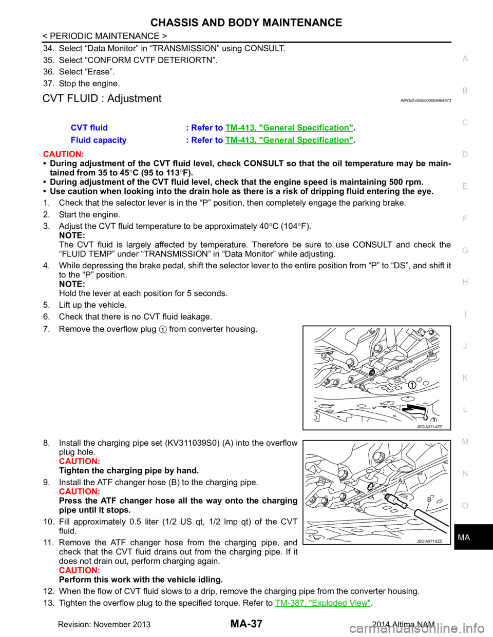
7. Remove the overflow plug from converter housing.
8. Install the charging pipe set (KV311039S0) (A) into the overflow plug hole.
CAUTION:
Tighten the charging pipe by hand.
9. Install the ATF changer hose (B) to the charging pipe. CAUTION:
Press the ATF changer hose all the way onto the charging
pipe until it stops.
10. Fill approximately 0.5 liter (1/2 US qt, 1/2 lmp qt) of the CVT
fluid.
11. Remove the ATF changer hose from the charging pipe, and check that the CVT fluid drains out from the charging pipe. If it
does not drain out, perform charging again.
CAUTION:
Perform this work with the vehicle idling.
12. When the flow of CVT fluid slows to a drip, re move the charging pipe from the converter housing.
13. Tighten the overflow plug to the specified torque. Refer to TM-387, "Exploded View"
.
CVT fluid : Refer to
TM-413, "General Specification"
.
Fluid capacity : Refer to TM-413, "General Specification"
.
JSDIA3714ZZ
JSDIA3713ZZ
Revision: November 20132014 Altima NAM
Page 3385 of 4801
![NISSAN TEANA 2014 Service Manual
PCS-36
< SYSTEM DESCRIPTION >[POWER DISTRIBUTION SYSTEM]
SYSTEM
SYSTEM
POWER DISTRIBUTION SYSTEM
POWER DISTRIBUTION SYSTEM : System DiagramINFOID:0000000009461624
POWER DISTRIBUTION SYSTEM
: System NISSAN TEANA 2014 Service Manual
PCS-36
< SYSTEM DESCRIPTION >[POWER DISTRIBUTION SYSTEM]
SYSTEM
SYSTEM
POWER DISTRIBUTION SYSTEM
POWER DISTRIBUTION SYSTEM : System DiagramINFOID:0000000009461624
POWER DISTRIBUTION SYSTEM
: System](/manual-img/5/57390/w960_57390-3384.png)
PCS-36
< SYSTEM DESCRIPTION >[POWER DISTRIBUTION SYSTEM]
SYSTEM
SYSTEM
POWER DISTRIBUTION SYSTEM
POWER DISTRIBUTION SYSTEM : System DiagramINFOID:0000000009461624
POWER DISTRIBUTION SYSTEM
: System DescriptionINFOID:0000000009461625
SYSTEM DESCRIPTION
• PDS (POWER DISTRIBUTION SYSTEM ) is the system that BCM controls with the operation of the push-
button ignition switch and performs the power distribution to each power circuit. This system is used instead
of the mechanical power supply changing mechanism wi th the operation of the conventional key cylinder.
• The push-button ignition switch can be operated when Intelligent Key is in the following condition.
- Intelligent Key is in the detection area of the inside key antenna.
- Intelligent Key backside is contacted to push-button ignition switch.
• The push-button ignition switch operation is input to BCM as a signal. BCM changes the power supply posi-
tion according to the status and operates the following relays to supply power to each power circuit.
- Ignition relay-1
- Ignition relay-2
- Accessory relay-1
- Accessory relay-2
- Front blower motor relay
NOTE:
The engine switch operation changes due to the conditions of brake pedal, selector lever and vehicle speed.
• The power supply position can be confirmed with the light ing of the indicators in the push-button ignition
switch.
BATTERY SAVER SYSTEM
When all the following conditions are met for 30 minutes, t he battery saver system will cut off the power supply
to prevent battery discharge.
• The ignition switch is in the ACC or ON position
• All doors are closed
• Selector lever is in the P (park) position
Reset Condition of Battery Saver System
In order to prevent the battery from discharging, the battery saver system will cut off the power supply when all
doors are closed, the selector lever is in P (park) positi on and the ignition switch is left in the ACC or ON posi-
tion for 30 minutes. If any of the following conditions are met the battery saver system is released and the
steering will change automatically to lock position from OFF position.
• Opening any door
• Operating door request switch on door handle
• Operating Intelligent Key
AWMIA1282GB
Revision: November 20132014 Altima NAMRevision: November 20132014 Altima NAM