2014 NISSAN TEANA Center
[x] Cancel search: CenterPage 690 of 4801
![NISSAN TEANA 2014 Service Manual
DAS
REAR VIEW CAMERA CALIBRATIONDAS-257
< BASIC INSPECTION > [MOD]
C
D E
F
G H
I
J
K L
M B
N P
A
>> Refer to DAS-257, "Work Procedure (Target Setting)".
Work Procedure (Target Setting)INFOID:00000](/manual-img/5/57390/w960_57390-689.png "NISSAN TEANA 2014 Service Manual
DAS
REAR VIEW CAMERA CALIBRATIONDAS-257
< BASIC INSPECTION > [MOD]
C
D E
F
G H
I
J
K L
M B
N P
A
>> Refer to DAS-257, \"Work Procedure (Target Setting)\".
Work Procedure (Target Setting)INFOID:00000")
DAS
REAR VIEW CAMERA CALIBRATIONDAS-257
< BASIC INSPECTION > [MOD]
C
D E
F
G H
I
J
K L
M B
N P
A
>> Refer to DAS-257, "Work Procedure (Target Setting)".
Work Procedure (Target Setting)INFOID:0000000009464908
CAUTION:
• Perform this operation in a horizontal position wh ere there is a clear view for 3 m (9.84 ft) backward
and 4 m (13.12 ft) wide.
• Place the target in a well-lig hted location. (Poor lighting may make it hard to adjust.)
• The target may not be detected when it shines by the reflected light of the sun or lighting.
• The target may not be detected when there is the same pattern of black and white as the target when
the pattern is within 0.5 m (1.64 ft) from either si de and upward/downward position from the target. (It
is desirable that the vehicle is pos itioned on a single-color floor.)
1.TARGET SETTING
1. Mark points “A”, “B”, “C” and “D” at the center of the lateral sur- face of each wheel.
NOTE:
Hang a string with a cone from the fender so as to pass through
the center of wheel, and then mark a point at the center of the
lateral surface of the wheel.
2. Draw line “LH” passing through points “A” and “B” on the left side of vehicle.
NOTE:
Approximately 2.2 m (7.22 ft) or more at the rear from the rear
axle.
3. Mark point “E” on the line “LH” at the positions 2125 mm (83.66
in) from point “B”.
4. Draw line “RH” passing through points “C” and “D” on the right side of vehicle in the same way as step 2.
5. Mark point “F” on the line “RH” at the positions 2125 mm (83.66 in) from point “D”.
6. Draw line “RW” passing through the points “E” and “F” on the rear of the vehicle. NOTE:
Approximately 1.8 m (5.91 ft) or more at bot h left and right sides from vehicle center.
7. Mark point “C
t” at the center of point “E” and “F” on the line “RW”.
CAUTION:
Make sure that “E” to “C
t” is equal to “F” to “Ct”.
8. Mark point "Lt" and "Rt" on the line "RW" at t he positions 1500 mm (59.06 in) from point "Ct".
9. Position the center of the ta rget mark to point of “Ct”.
Side distance (S
d): “B” – “E” (“D” – “F”)
: 2125 mm (83.66 in)
Left distance (L
d): “Ct” – “Lt” : 1500 mm (59.06 in)
Right distance (R
d): “Ct” – “Rt” : 1500 mm (59.06 in)
ALOIA0187GB
PKIB7667E
Revision: November 20132014 Altima NAMRevision: November 20132014 Altima NAM
Page 691 of 4801
![NISSAN TEANA 2014 Service Manual
DAS-258
< BASIC INSPECTION >[MOD]
REAR VIEW CAMERA CALIBRATION
CAUTION:
Make sure that the black/white pattern of the center target is rotated as compared with the left and
right targets.
>> Go to](/manual-img/5/57390/w960_57390-690.png "NISSAN TEANA 2014 Service Manual
DAS-258
< BASIC INSPECTION >[MOD]
REAR VIEW CAMERA CALIBRATION
CAUTION:
Make sure that the black/white pattern of the center target is rotated as compared with the left and
right targets.
>> Go to")
DAS-258
< BASIC INSPECTION >[MOD]
REAR VIEW CAMERA CALIBRATION
CAUTION:
Make sure that the black/white pattern of the center target is rotated as compared with the left and
right targets.
>> Go to DAS-258, "Work Procedure (Rear View Camera Calibration)"
.
Work Procedure (Rear View Camera Calibration)INFOID:0000000009464909
CAUTION:
Perform the calibration under the sp ecified vehicle condition (fuel full, no-load, specified tire pressure,
etc.). Refer to DAS-256, "Work Procedure (Preparation)"
.
1.CHECK REAR VIEW CAMERA HEIGHT
Measure the rear view camera height “H”.
>> GO TO 2.
2.REAR VIEW CAMERA CALIBRATION
1. Select “Work Support” on “AVM” with CONSULT.
2. Select “REAR CAMERA ITS”.
3. Select "OK". CAUTION:
• Perform the calibration after the ignition or engine has been kept on for at least 10 minutes to
stabilize camera.
• Operate CONSULT outside the vehicle, and close al l doors to retain appropriate vehicle altitude.
4. Input the rear view camera height "H", and then touch "APPLY".
5. Confirm that the same value is displayed on the center display.
6. Confirm the following items:
- The target should be accurately placed.
- The vehicle should be stopped.
- The vehicle should be under the specified vehicle condition.
7. Select “Start” to perform calibration.
8. Confirm the displayed item.
- “Completed”: Select “Completion”.
- Otherwise, perform the following services:
ALOIA0192GB
ALOIA0188ZZ
Revision: November 20132014 Altima NAMRevision: November 20132014 Altima NAM
Page 934 of 4801

DLK-166
< SYMPTOM DIAGNOSIS >
SQUEAK AND RATTLE TROUBLE DIAGNOSES
1. Cluster lid A and the instrument panel
2. Acrylic lens and combination meter housing
3. Instrument panel to front pillar finisher
4. Instrument panel to windshield
5. Instrument panel pins
6. Wiring harnesses behind the combination meter
7. A/C defroster duct and duct joint
These incidents can usually be located by tapping or moving the components to duplicate the noise or by
pressing on the components while driving to stop the noise. Most of these incidents can be repaired by apply-
ing felt cloth tape or silicone spray (in hard to reach areas). Urethane pads can be used to insulate wiring har-
ness.
CAUTION:
Do not use silicone spray to isolate a squeak or ra ttle. If you saturate the area with silicone, you will
not be able to recheck the repair.
CENTER CONSOLE
Components to pay attention to include:
1. Shift selector assembly cover to finisher
2. A/C control unit and cluster lid C
3. Wiring harnesses behind audio and A/C control unit
The instrument panel repair and isolation pr ocedures also apply to the center console.
DOORS
Pay attention to the:
1. Finisher and inner panel making a slapping noise
2. Inside handle escutcheon to door finisher
3. Wiring harnesses tapping
4. Door striker out of alignment causing a popping noise on starts and stops
Tapping or moving the components or pressing on them wh ile driving to duplicate the conditions can isolate
many of these incidents. You can usually insulate the areas with felt cloth tape or insulator foam blocks from
the NISSAN Squeak and Rattle Kit (J-50397) to repair the noise.
TRUNK
Trunk noises are often caused by a loose jack or loose items put into the trunk by the owner.
In addition look for:
1. Trunk lid bumpers out of adjustment
2. Trunk lid striker out of adjustment
3. The trunk lid torsion bars knocking together
4. A loose license plate or bracket
Most of these incidents can be repaired by adjusting, se curing or insulating the item(s) or component(s) caus-
ing the noise.
SUNROOF/HEADLINING
Noises in the sunroof/headlining area c an often be traced to one of the following:
1. Sunroof lid, rail, linkage or seals making a rattle or light knocking noise
2. Sun visor shaft shaking in the holder
3. Front or rear windshield touching headlining and squeaking
Again, pressing on the components to stop the noise while duplicating the conditions can isolate most of these
incidents. Repairs usually consist of insulating with felt cloth tape.
OVERHEAD CONSOLE (FRONT AND REAR)
Overhead console noises are often caused by the c onsole panel clips not being engaged correctly. Most of
these incidents are repaired by pushing up on the c onsole at the clip locations until the clips engage.
In addition look for:
1. Loose harness or harness connectors.
2. Front console map/reading lamp lens loose.
Revision: November 20132014 Altima NAMRevision: November 20132014 Altima NAM
Page 945 of 4801

HOOD
DLK-177
< REMOVAL AND INSTALLATION >
C
D E
F
G H
I
J
L
M A
B
DLK
N
O P
2. Attach the hood lock release cable (3) and the fuel filler door release cable (2) to the hood lock/fuel filler door release handle
assembly (1).
3. Place hood lock/fuel filler door release handle assembly in posi- tion and retain with bolts (A).
4. Check that the cable is not offset from the center of the grommet
and seat the grommet into the upper dash hole.
NOTE:
Make sure that the marked area (A) of the cable is located as
shown after mounting grommet to dash upper assembly.
Apply sealant around the grommet at * mark.
5. Position the hood lock release cable and clip it into place.
6. Install the hoodledge finisher (LH) and retain with clips.
7. Connect the hood lock release cable to the hood lock assembly.
8. Install the fender protector (LH). Refer to EXT-26, "FENDER PROTECTOR : Removal and Installation"
.
9. Perform hood fitting adjustment. Refer to DLK-172, "HOOD ASSEMBLY : Adjustment"
.
10. Perform the hood lock control inspection.
INSPECTION
NOTE:
If the hood lock release cable is bent or deformed, replace it.
1. Check that the secondary latch is properly engaged wi th the secondary striker and meets specification
provided (B) with hood's own weight.
ALKIA2665ZZ
ALKIA2139ZZ
PIIB5802E
PIIB5794E
Revision: November 20132014 Altima NAMRevision: November 20132014 Altima NAM
Page 951 of 4801

FRONT FENDERDLK-183
< REMOVAL AND INSTALLATION >
C
D E
F
G H
I
J
L
M A
B
DLK
N
O P
9. Adjust the clearance (E) and surface hei ght (F) between the front fender and the hood.
10. Adjust the clearance (M) and surface height (N ) between the front fender and the body side outer.
11. Tighten the inner front fender bolts.
12. Adjust the clearance (G) and the surface height (H) between the front fender and the front fascia.
13. Tighten the front fender to front fascia and bracket screws.
14. Install front fascia.
15. Install the center mudguard. Refer to EXT-30, "Removal and Installation"
.
16. Install the front fender protector. Refer to EXT-26, "FENDER PROTECTOR : Removal and Installation"
.
17. Install the cowl top side trim cover.
18. Install hoodledge finisher.
CAUTION:
• If the clearance measurements cannot be corrected by adjusting the fender, adjust the following as
necessary.
- Hood assembly: Refer to DLK-172, "HOOD ASSEMBLY : Adjustment"
.
- Front door: Refer to DLK-186, "DOOR ASSEMB LY : Adjustment"
.
• After adjusting, apply touch-up paint (body co lor) onto the head of the front fender bolts.
Revision: November 20132014 Altima NAMRevision: November 20132014 Altima NAM
Page 954 of 4801

DLK-186
< REMOVAL AND INSTALLATION >
FRONT DOOR
DOOR ASSEMBLY : Adjustment
INFOID:0000000009461934
Check the clearance and surface height between front door and each part by visual inspection and tactile feel.
1. Front fender 2. Front door assembly 3. Rear door assembly
4. Center mudguard 5. Center pillar 6. Outer sill
ALKIA2709ZZ
Revision: November 20132014 Altima NAMRevision: November 20132014 Altima NAM
Page 960 of 4801
DLK-192
< REMOVAL AND INSTALLATION >
REAR DOOR
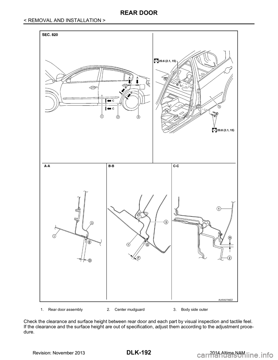
Check the clearance and surface height between rear door and each part by visual inspection and tactile feel.
If the clearance and the surface height are out of specific ation, adjust them according to the adjustment proce-
dure.
1. Rear door assembly 2. Center mudguard 3. Body side outer
ALKIA2739ZZ
Revision: November 20132014 Altima NAMRevision: November 20132014 Altima NAM
Page 961 of 4801

REAR DOORDLK-193
< REMOVAL AND INSTALLATION >
C
D E
F
G H
I
J
L
M A
B
DLK
N
O P
Unit: mm (in)
LONGITUDINAL CLEARANCE
1. Remove the center pillar upper finisher. Refer to INT-24, "CENTER PILLAR UPPER FINISHER : Removal
and Installation".
2. Loosen the rear door upper hinge nuts.
3. Loosen the rear door lower hinge bolts.
4. Move the rear door forward or backward as necessary until within specifications provided.
5. Tighten the lower hinge bolts to specification.
6. Tighten the upper hinge nuts to specification.
7. Install the center pillar upper finisher. Refer to INT-24, "CENTER PILLAR UPPER FINISHER : Removal
and Installation".
SURFACE HEIGHT ADJUSTMENT
1. Loosen the rear door hinge nuts (door side) (A).
2. Move the top and/or the bottom of the rear door (1) in or out as necessary until it is within specifications provided.
3. Tighten the rear door hinge nuts (door side) (A) to specification.
CAUTION:
• Check rear door hinge rotating poin t for poor lubrication. If necessary, apply a suitable multi-pur-
pose grease.
• After adjusting, apply touch-up paint (body color) to the head of rear door hinge bolts and nuts.
Section Item Measurement Standard
A – A D Clearance 3.6
± 1.0 (0.14 ± 0.04)
E Surface height 0.0 ± 1.0 (0.00 ± 0.04)
B – B F Clearance 3.6
± 1.0 (0.14 ± 0.04)
G Surface height 0.0 ± 1.0 (0.0 ± 0.04)
C – C H Clearance 7.1 ± 1.7 (0.28 ± 0.07)
Rear door lower hinge
bolts 20.6 N·m (2.1 kg-m, 15 ft-lb)
Rear door upper hinge
nuts 20.6 N·m (2.1 kg-m, 15 ft-lb)
Rear door nuts 24.5 N·m (2.5 kg-m, 18 ft-lb)
ALKIA2710ZZ
Revision: November 20132014 Altima NAMRevision: November 20132014 Altima NAM