Page 4395 of 4801
![NISSAN TEANA 2014 Service Manual
TM-180
< REMOVAL AND INSTALLATION >[CVT: RE0F10D]
CVT SHIFT SELECTOR
4. Remove the shift selector handle (1).
a. Release the shift selector handle cover (2) using a suitable tool from the base of t NISSAN TEANA 2014 Service Manual
TM-180
< REMOVAL AND INSTALLATION >[CVT: RE0F10D]
CVT SHIFT SELECTOR
4. Remove the shift selector handle (1).
a. Release the shift selector handle cover (2) using a suitable tool from the base of t](/manual-img/5/57390/w960_57390-4394.png)
TM-180
< REMOVAL AND INSTALLATION >[CVT: RE0F10D]
CVT SHIFT SELECTOR
4. Remove the shift selector handle (1).
a. Release the shift selector handle cover (2) using a suitable tool from the base of the shift selector handle (1).
b. Remove the shift selector handle clip (A).
c. Pull upward and remove the shift selector handle (1).
5. Remove the center console. Refer to IP-18, "Removal and Installation"
.
6. Release the harness clip, then disconnect the harness connector from CVT shift selector.
7. Depress shift lock override button and move CVT shift selector to "P" position“”.
8. Remove the control cable from the CV T shift selector assembly. Refer to TM-181, "Exploded View"
.
9. Remove the four CVT shift selector assembly nuts and the CVT shift selector assembly from the vehicle.
INSTALLATION
Installation is in the reverse order of removal.
• When installing control cable (1) to the CVT shift selector assembly (2), check that control cable is fully pressed in until it stops with the
ribbed surface (A) facing upward.
NOTE:
Apply multi-purpose grease to control cable eye before installation.
• Adjust control cable as necessary. Refer to TM-182, "Inspection
and Adjustment".
InspectionINFOID:0000000009464122
INSPECTION AFTER INSTALLATION
Check the CVT shift selector position. Refer to TM-87, "Inspection".
If a malfunction is found, adjust the CVT position. Refer to TM-87, "Adjustment"
.
ALDIA0319ZZ
JSDIA1624ZZ
Revision: November 20132014 Altima NAMRevision: November 20132014 Altima NAM
Page 4396 of 4801
![NISSAN TEANA 2014 Service Manual
CONTROL CABLETM-181
< REMOVAL AND INSTALLATION > [CVT: RE0F10D]
C
EF
G H
I
J
K L
M A
B
TM
N
O P
CONTROL CABLE
Exploded ViewINFOID:0000000009464123
Removal and InstallationINFOID:0000000009464124
CAU NISSAN TEANA 2014 Service Manual
CONTROL CABLETM-181
< REMOVAL AND INSTALLATION > [CVT: RE0F10D]
C
EF
G H
I
J
K L
M A
B
TM
N
O P
CONTROL CABLE
Exploded ViewINFOID:0000000009464123
Removal and InstallationINFOID:0000000009464124
CAU](/manual-img/5/57390/w960_57390-4395.png)
CONTROL CABLETM-181
< REMOVAL AND INSTALLATION > [CVT: RE0F10D]
C
EF
G H
I
J
K L
M A
B
TM
N
O P
CONTROL CABLE
Exploded ViewINFOID:0000000009464123
Removal and InstallationINFOID:0000000009464124
CAUTION:
Always apply the parking brake before pe rforming removal and installation.
REMOVAL
1. Apply the parking brake.
CAUTION:
Make sure the vehicle cannot move with the parking brake applied.
2. Remove the front air duct and air cleaner case assembly. Refer to EM-29, "Removal and Installation"
.
3. Remove the control cable nut ( ), using suitable tool.
4. Remove control cable (2) from manual lever (A).
5. Remove the lock plate (3) from control cable (2).
6. Remove control cable (2) from bracket (1).
7. Remove center console. Refer to IP-18, "Removal and Installation"
.
8. Disconnect the ITS control unit harness connectors and remove the ITS control unit (if equipped). Refer to
AV-436, "Removal and Installation"
.
1. Lock plate 2. Transaxle assembly 3. Bracket
4. Control cable 5. CVT shift selector assembly A. Manual lever
B. Retainer grommet
ALDIA0351GB
ALDIA0357ZZ
Revision: November 20132014 Altima NAMRevision: November 20132014 Altima NAM
Page 4594 of 4801
![NISSAN TEANA 2014 Service Manual
CVT SHIFT SELECTORTM-379
< REMOVAL AND INSTALLATION > [CVT: RE0F10E]
C
EF
G H
I
J
K L
M A
B
TM
N
O P
4. Remove the shift selector handle (1).
a. Release the shift selector handle cover (2) using a NISSAN TEANA 2014 Service Manual
CVT SHIFT SELECTORTM-379
< REMOVAL AND INSTALLATION > [CVT: RE0F10E]
C
EF
G H
I
J
K L
M A
B
TM
N
O P
4. Remove the shift selector handle (1).
a. Release the shift selector handle cover (2) using a](/manual-img/5/57390/w960_57390-4593.png)
CVT SHIFT SELECTORTM-379
< REMOVAL AND INSTALLATION > [CVT: RE0F10E]
C
EF
G H
I
J
K L
M A
B
TM
N
O P
4. Remove the shift selector handle (1).
a. Release the shift selector handle cover (2) using a suitable tool from the base of the shift selector handle (1).
b. Remove the shift selector handle clip (A).
c. Pull upward and remove the shift selector handle (1).
5. Remove the center console. Refer to IP-18, "Removal and Installation"
.
6. Release the harness clip, then disconnect the harness connector from CVT shift selector.
7. Depress shift lock override button and move CVT shift selector to "P" position“”.
8. Remove the control cable from the CV T shift selector assembly. Refer to TM-181, "Exploded View"
.
9. Remove the four CVT shift selector assembly nuts and the CVT shift selector assembly from the vehicle.
INSTALLATION
Installation is in the reverse order of removal.
• When installing control cable (1) to the CVT shift selector assembly (2), check that control cable is full y pressed in until it stops with the
ribbed surface (A) facing upward.
NOTE:
Apply multi-purpose grease to cont rol cable eye before installation.
• Adjust control cable as necessary. Refer to TM-381, "Inspection
and Adjustment".
InspectionINFOID:0000000009464334
INSPECTION AFTER INSTALLATION
Check the CVT shift selector position. Refer to TM-289, "Inspection".
If a malfunction is found, adjust the CVT position. Refer to TM-289, "Adjustment"
.
ALDIA0353ZZ
JSDIA1624ZZ
Revision: November 20132014 Altima NAMRevision: November 20132014 Altima NAM
Page 4595 of 4801
![NISSAN TEANA 2014 Service Manual
TM-380
< REMOVAL AND INSTALLATION >[CVT: RE0F10E]
CONTROL CABLE
CONTROL CABLE
Exploded ViewINFOID:0000000009464335
Removal and InstallationINFOID:0000000009464336
CAUTION:
Always apply the parking b NISSAN TEANA 2014 Service Manual
TM-380
< REMOVAL AND INSTALLATION >[CVT: RE0F10E]
CONTROL CABLE
CONTROL CABLE
Exploded ViewINFOID:0000000009464335
Removal and InstallationINFOID:0000000009464336
CAUTION:
Always apply the parking b](/manual-img/5/57390/w960_57390-4594.png)
TM-380
< REMOVAL AND INSTALLATION >[CVT: RE0F10E]
CONTROL CABLE
CONTROL CABLE
Exploded ViewINFOID:0000000009464335
Removal and InstallationINFOID:0000000009464336
CAUTION:
Always apply the parking brake before pe rforming removal and installation.
INSTALLATION
1. Apply the parking brake.
CAUTION:
Make sure the vehicle cannot move with the parking brake applied.
2. Remove the front air duct and air cleaner case assembly. Refer to EM-29, "Removal and Installation"
.
3. Remove the control cable nut ( ), using suitable tool.
4. Remove control cable (2) from manual lever (A).
5. Remove the lock plate (3) from control cable (2).
6. Remove control cable (2) from bracket (1).
7. Remove center console. Refer to IP-18, "Removal and Installation"
.
8. Disconnect the ITS control unit harness connectors and remove the ITS control unit (if equipped). Refer to
AV-436, "Removal and Installation"
.
1. Lock plate 2. Transaxle assembly 3. Bracket
4. Control cable 5. CVT shift selector assembly A. Manual lever
B. Retainer grommet
ALDIA0352GB
ALDIA0360ZZ
Revision: November 20132014 Altima NAMRevision: November 20132014 Altima NAM
Page 4636 of 4801

VTL-8
< REMOVAL AND INSTALLATION >
DUCTS AND GRILLES
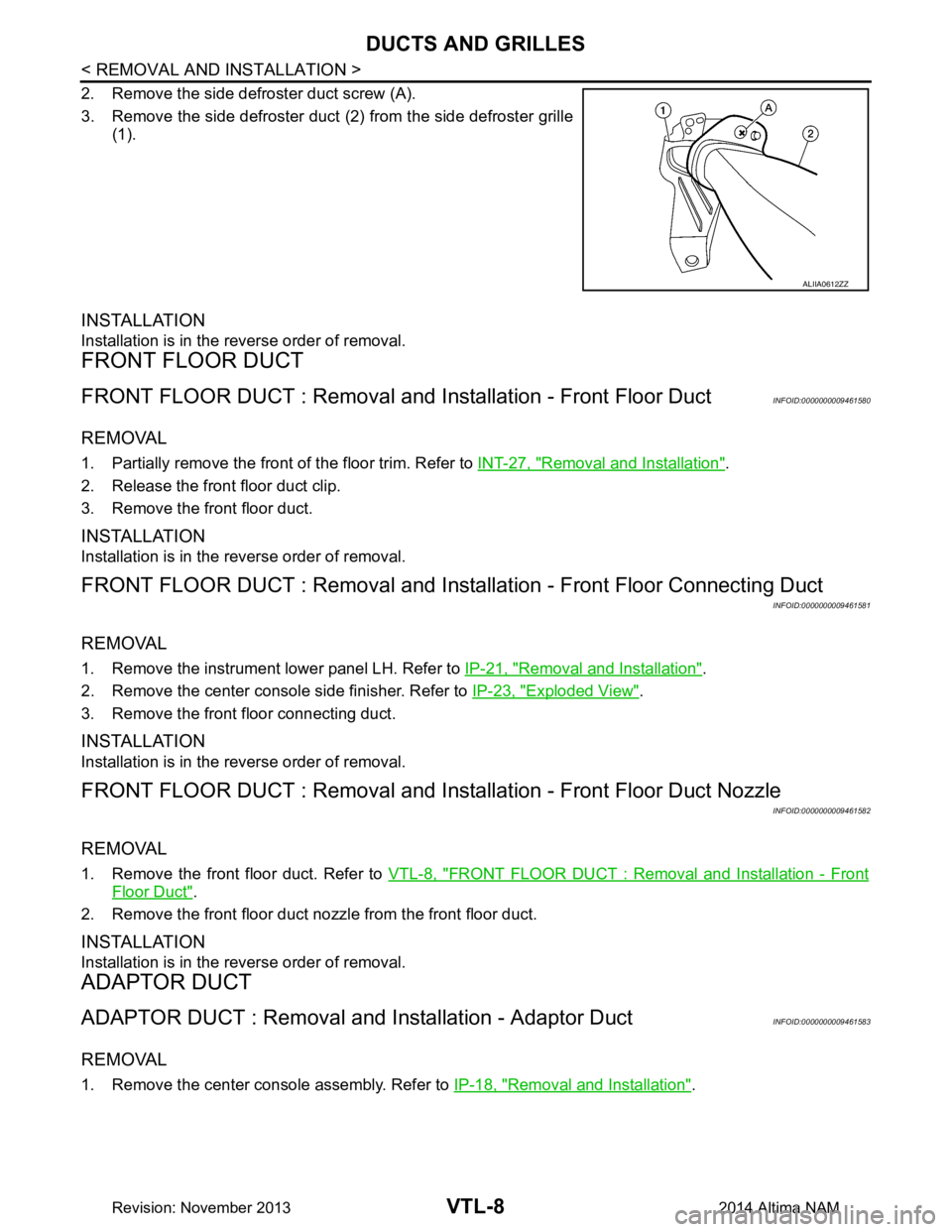
2. Remove the side defroster duct screw (A).
3. Remove the side defroster duct (2) from the side defroster grille
(1).
INSTALLATION
Installation is in the reverse order of removal.
FRONT FLOOR DUCT
FRONT FLOOR DUCT : Removal and In stallation - Front Floor DuctINFOID:0000000009461580
REMOVAL
1. Partially remove the front of the floor trim. Refer to INT-27, "Removal and Installation".
2. Release the front floor duct clip.
3. Remove the front floor duct.
INSTALLATION
Installation is in the reverse order of removal.
FRONT FLOOR DUCT : Removal and Installa tion - Front Floor Connecting Duct
INFOID:0000000009461581
REMOVAL
1. Remove the instrument lower panel LH. Refer to IP-21, "Removal and Installation".
2. Remove the center console side finisher. Refer to IP-23, "Exploded View"
.
3. Remove the front floor connecting duct.
INSTALLATION
Installation is in the reverse order of removal.
FRONT FLOOR DUCT : Removal and Insta llation - Front Floor Duct Nozzle
INFOID:0000000009461582
REMOVAL
1. Remove the front floor duct. Refer to VTL-8, "FRONT FLOOR DUCT : Removal and Installation - Front
Floor Duct".
2. Remove the front floor duct nozzle from the front floor duct.
INSTALLATION
Installation is in the reverse order of removal.
ADAPTOR DUCT
ADAPTOR DUCT : Removal and Installation - Adaptor DuctINFOID:0000000009461583
REMOVAL
1. Remove the center console assembly. Refer to IP-18, "Removal and Installation".
ALIIA0612ZZ
Revision: November 20132014 Altima NAM
Page 4637 of 4801

DUCTS AND GRILLESVTL-9
< REMOVAL AND INSTALLATION >
C
D E
F
G H
J
K L
M A
B
VTL
N
O P
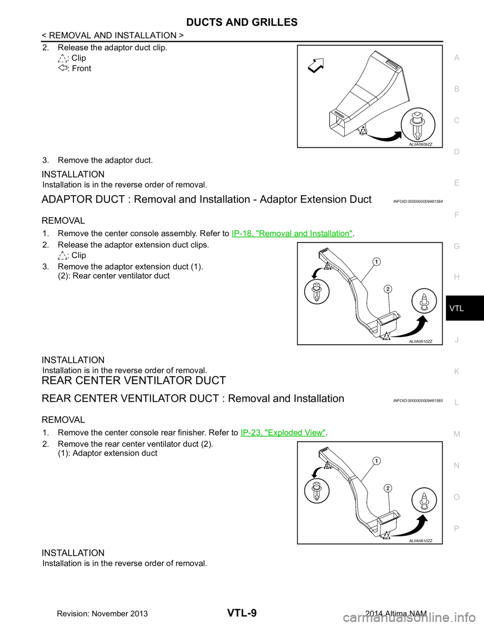
2. Release the adaptor duct clip. : Clip
: Front
3. Remove the adaptor duct.
INSTALLATION
Installation is in the reverse order of removal.
ADAPTOR DUCT : Removal and Insta llation - Adaptor Extension DuctINFOID:0000000009461584
REMOVAL
1. Remove the center console assembly. Refer to IP-18, "Removal and Installation".
2. Release the adaptor extension duct clips. : Clip
3. Remove the adaptor extension duct (1). (2): Rear center ventilator duct
INSTALLATION
Installation is in the reverse order of removal.
REAR CENTER VENTILATOR DUCT
REAR CENTER VENTILATOR DUCT : Removal and InstallationINFOID:0000000009461585
REMOVAL
1. Remove the center console rear finisher. Refer to IP-23, "Exploded View".
2. Remove the rear center ventilator duct (2). (1): Adaptor extension duct
INSTALLATION
Installation is in the reverse order of removal.
ALIIA0609ZZ
ALIIA0610ZZ
ALIIA0610ZZ
Revision: November 20132014 Altima NAM
Page 4638 of 4801
VTL-10
< REMOVAL AND INSTALLATION >
DUCTS AND GRILLES
Exploded View
INFOID:0000000009461586
FRONT
REAR
CENTER VENTIL AT O R G R I L L E
ALIIA0637ZZ
1. Instrument panel 2. Side defroster grille (LH) 3. Side ventilator grille (LH)
4. Center ventilator grille 5. Cluster lid C 6. Side ventilator grille (RH)
7. Side defroster grille (LH)
ALIIA0638ZZ
1. Center console assembly 2. Rear center ventilator grille
Revision: November 20132014 Altima NAM
Page 4640 of 4801
VTL-12
< REMOVAL AND INSTALLATION >
DUCTS AND GRILLES
2. Remove the side defroster grille screws (A).
3. Remove the side defroster grille.
INSTALLATION
Installation is in the reverse order of removal.
REAR CENTER VENTILATOR GRILLE
REAR CENTER VENTILATOR GRI LLE : Removal and InstallationINFOID:0000000009461590
REMOVAL
1. Remove the center console rear finisher. Refer to IP-23, "Exploded View".
2. Release the rear center ventilator grille pawls using a suitable tool.
: Pawl
3. Remove the rear center ventilator grille.
INSTALLATION
Installation is in the reverse order of removal.
ALIIA0616ZZ
ALIIA0615ZZ
Revision: November 20132014 Altima NAM