2014 NISSAN TEANA center console
[x] Cancel search: center consolePage 2587 of 4801
SQUEAK AND RATTLE TROUBLE DIAGNOSESGW-7
< SYMPTOM DIAGNOSIS >
C
D E
F
G H
I
J
L
M A
B
GW
N
O P
INSTRUMENT PANEL
Most incidents are caused by contact and movement between:
1. Cluster lid A and the instrument panel
2. Acrylic lens and combination meter housing
3. Instrument panel to front pillar finisher
4. Instrument panel to windshield
5. Instrument panel pins
6. Wiring harnesses behind the combination meter
7. A/C defroster duct and duct joint
These incidents can usually be located by tapping or moving the components to duplicate the noise or by
pressing on the components while driving to stop the noi se. Most of these incidents can be repaired by apply-
ing felt cloth tape or silicone spray (in hard to reach areas). Urethane pads can be used to insulate wiring har-
ness.
CAUTION:
Do not use silicone spray to isolate a squeak or ra ttle. If you saturate the area with silicone, you will
not be able to recheck the repair.
CENTER CONSOLE
Components to pay attention to include:
1. Shift selector assembly cover to finisher
2. A/C control unit and cluster lid C
3. Wiring harnesses behind audio and A/C control unit
The instrument panel repair and isolation pr ocedures also apply to the center console.
DOORS
Pay attention to the:
1. Finisher and inner panel making a slapping noise
2. Inside handle escutcheon to door finisher
3. Wiring harnesses tapping
4. Door striker out of alignment causing a popping noise on starts and stops
Tapping or moving the components or pressing on them wh ile driving to duplicate the conditions can isolate
many of these incidents. You can usually insulate the ar eas with felt cloth tape or insulator foam blocks from
the NISSAN Squeak and Rattle Kit (J-50397) to repair the noise.
TRUNK
Trunk noises are often caused by a loose jack or loose items put into the trunk by the owner.
In addition look for:
1. Trunk lid bumpers out of adjustment
2. Trunk lid striker out of adjustment
3. The trunk lid torsion bars knocking together
4. A loose license plate or bracket
Most of these incidents can be repaired by adjusting, se curing or insulating the item(s) or component(s) caus-
ing the noise.
SUNROOF/HEADLINING
Noises in the sunroof/headlining area can often be traced to one of the following:
1. Sunroof lid, rail, linkage or seals making a rattle or light knocking noise
2. Sun visor shaft shaking in the holder
3. Front or rear windshield touching headlining and squeaking
Again, pressing on the components to stop the noise while duplicating the conditions can isolate most of these
incidents. Repairs usually consist of insulating with felt cloth tape.
OVERHEAD CONSOLE (FRONT AND REAR)
Overhead console noises are often caused by the cons ole panel clips not being engaged correctly. Most of
these incidents are repaired by pushing up on the c onsole at the clip locations until the clips engage.
In addition look for:
Revision: November 20132014 Altima NAM
Page 2902 of 4801
SQUEAK AND RATTLE TROUBLE DIAGNOSESINT-11
< SYMPTOM DIAGNOSIS >
C
D E
F
G H
I
K L
M A
B
INT
N
O P
INSTRUMENT PANEL
Most incidents are caused by contact and movement between:
1. Cluster lid A and the instrument panel
2. Acrylic lens and combination meter housing
3. Instrument panel to front pillar finisher
4. Instrument panel to windshield
5. Instrument panel pins
6. Wiring harnesses behind the combination meter
7. A/C defroster duct and duct joint
These incidents can usually be located by tapping or moving the components to duplicate the noise or by
pressing on the components while driving to stop the noi se. Most of these incidents can be repaired by apply-
ing felt cloth tape or silicone spray (in hard to reach areas). Urethane pads can be used to insulate wiring har-
ness.
CAUTION:
Do not use silicone spray to isolate a squeak or ra ttle. If you saturate the area with silicone, you will
not be able to recheck the repair.
CENTER CONSOLE
Components to pay attention to include:
1. Shift selector assembly cover to finisher
2. A/C control unit and cluster lid C
3. Wiring harnesses behind audio and A/C control unit
The instrument panel repair and isolation pr ocedures also apply to the center console.
DOORS
Pay attention to the:
1. Finisher and inner panel making a slapping noise
2. Inside handle escutcheon to door finisher
3. Wiring harnesses tapping
4. Door striker out of alignment causing a popping noise on starts and stops
Tapping or moving the components or pressing on them wh ile driving to duplicate the conditions can isolate
many of these incidents. You can usually insulate the ar eas with felt cloth tape or insulator foam blocks from
the NISSAN Squeak and Rattle Kit (J-50397) to repair the noise.
TRUNK
Trunk noises are often caused by a loose jack or loose items put into the trunk by the owner.
In addition look for:
1. Trunk lid bumpers out of adjustment
2. Trunk lid striker out of adjustment
3. The trunk lid torsion bars knocking together
4. A loose license plate or bracket
Most of these incidents can be repaired by adjusting, se curing or insulating the item(s) or component(s) caus-
ing the noise.
SUNROOF/HEADLINING
Noises in the sunroof/headlining area can often be traced to one of the following:
1. Sunroof lid, rail, linkage or seals making a rattle or light knocking noise
2. Sun visor shaft shaking in the holder
3. Front or rear windshield touching headlining and squeaking
Again, pressing on the components to stop the noise while duplicating the conditions can isolate most of these
incidents. Repairs usually consist of insulating with felt cloth tape.
OVERHEAD CONSOLE (FRONT AND REAR)
Overhead console noises are often caused by the cons ole panel clips not being engaged correctly. Most of
these incidents are repaired by pushing up on the c onsole at the clip locations until the clips engage.
In addition look for:
Revision: November 20132014 Altima NAM
Page 2918 of 4801
FLOOR TRIMINT-27
< REMOVAL AND INSTALLATION >
C
D E
F
G H
I
K L
M A
B
INT
N
O P
FLOOR TRIM
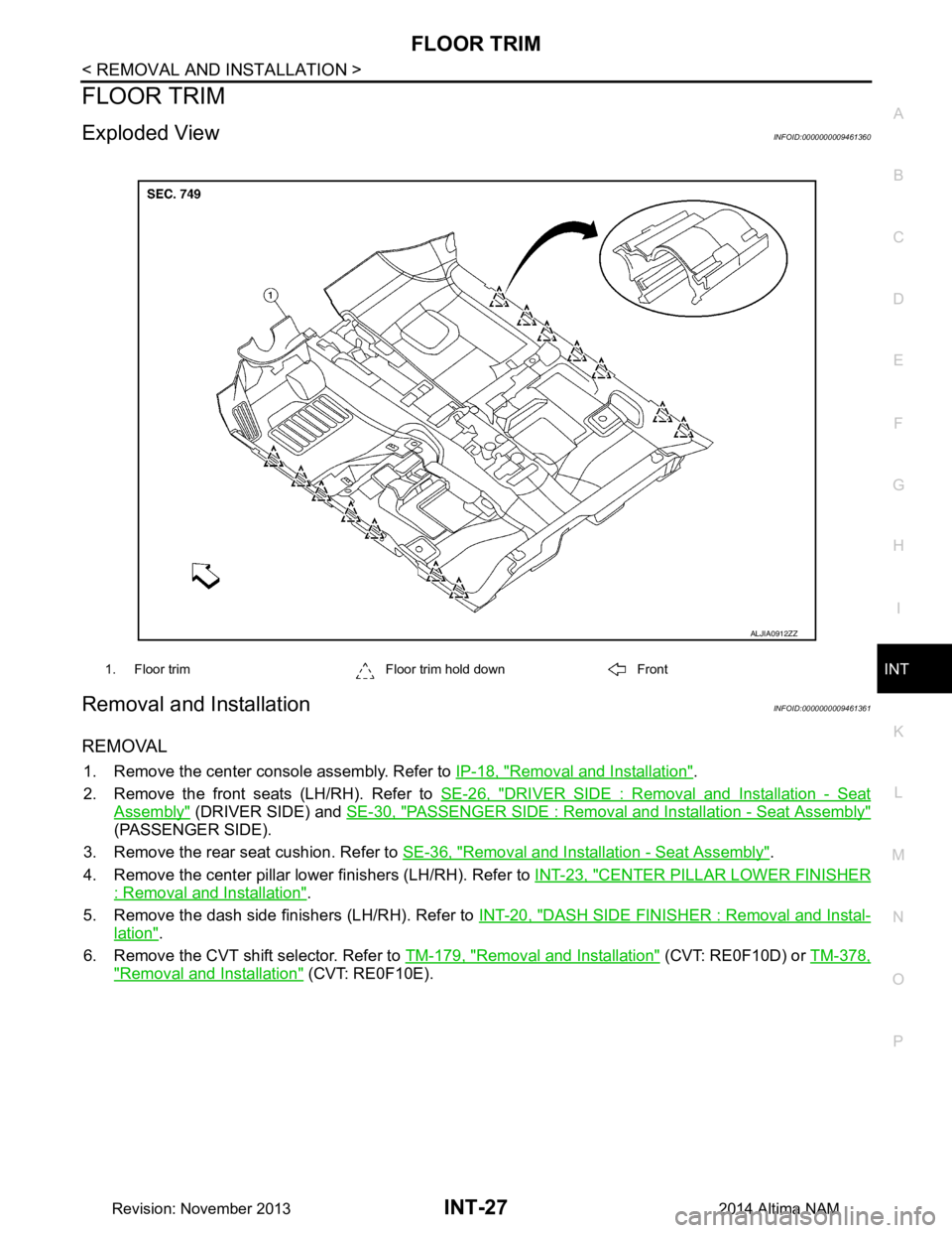
Exploded ViewINFOID:0000000009461360
Removal and InstallationINFOID:0000000009461361
REMOVAL
1. Remove the center console assembly. Refer to IP-18, "Removal and Installation".
2. Remove the front seats (LH/RH). Refer to SE-26, "DRIVER SIDE : Removal and Installation - Seat
Assembly" (DRIVER SIDE) and SE-30, "PASSENGER SIDE : Removal and Installation - Seat Assembly"
(PASSENGER SIDE).
3. Remove the rear seat cushion. Refer to SE-36, "Removal and Installation - Seat Assembly"
.
4. Remove the center pillar lower finishers (LH/RH). Refer to INT-23, "CENTER PILLAR LOWER FINISHER
: Removal and Installation".
5. Remove the dash side finishers (LH/RH). Refer to INT-20, "DASH SIDE FINISHER : Removal and Instal-
lation".
6. Remove the CVT shift selector. Refer to TM-179, "Removal and Installation"
(CVT: RE0F10D) or TM-378,
"Removal and Installation" (CVT: RE0F10E).
1. Floor trim Floor trim hold down Front
ALJIA0912ZZ
Revision: November 20132014 Altima NAM
Page 2927 of 4801

IP-1
BODY INTERIOR
C
D E
F
G H
I
K L
M
SECTION IP
A
B
IP
N
O P
CONTENTS
INSTRUMENT PANEL
PRECAUTION ................ ...............................2
PRECAUTIONS .............................................. .....2
Precaution for Supplemental Restraint System
(SRS) "AIR BAG" and "SEAT BELT PRE-TEN-
SIONER" ............................................................. ......
2
Precaution for Work ..................................................2
PREPARATION ............................................3
PREPARATION .............................................. .....3
Special Service Tools ........................................ ......3
Commercial Service Tools .......................................3
CLIP LIST ............................................................4
Descriptions for Clips .......................................... ......4
SYMPTOM DIAGNOSIS ...............................8
SQUEAK AND RATTLE TROUBLE DIAG-
NOSES ........................................................... .....
8
Work Flow ........................................................... ......8
Generic Squeak and Rattle Troubleshooting ............9
Diagnostic Worksheet .............................................12
REMOVAL AND INSTALLATION ...............14
INSTRUMENT PANEL ASSEMBLY .............. ....14
Exploded View ..................................................... ....14
Removal and Installation .........................................15
STEERING COLUMN COVERS .......................17
Removal and Installation .........................................17
CENTER CONSOLE ASSEMBLY ....................18
Exploded View .........................................................18
Removal and Installation .........................................18
CLUSTER LID A ...............................................19
Removal and Installation .........................................19
CLUSTER LID C ...............................................20
Cluster Lid C ............................................................20
Cluster Lid C Lower .................................................20
INSTRUMENT LOWER PANEL LH ..................21
Removal and Installation .........................................21
GLOVE BOX ASSEMBLY ................................22
Removal and Installation .........................................22
UNIT DISASSEMBLY AND ASSEMBLY ....23
CENTER CONSOLE ASSEMBLY ....................23
Exploded View ..................................................... ....23
Disassembly and Assembly .....................................23
Revision: November 20132014 Altima NAM
Page 2936 of 4801

IP-10
< SYMPTOM DIAGNOSIS >
SQUEAK AND RATTLE TROUBLE DIAGNOSES
INSTRUMENT PANEL
Most incidents are caused by contact and movement between:
1. Cluster lid A and the instrument panel
2. Acrylic lens and combination meter housing
3. Instrument panel to front pillar finisher
4. Instrument panel to windshield
5. Instrument panel pins
6. Wiring harnesses behind the combination meter
7. A/C defroster duct and duct joint
These incidents can usually be located by tapping or moving the components to duplicate the noise or by
pressing on the components while driving to stop the noise. Most of these incidents can be repaired by apply-
ing felt cloth tape or silicone spray (in hard to reach areas). Urethane pads can be used to insulate wiring har-
ness.
CAUTION:
Do not use silicone spray to isolate a squeak or ra ttle. If you saturate the area with silicone, you will
not be able to recheck the repair.
CENTER CONSOLE
Components to pay attention to include:
1. Shift selector assembly cover to finisher
2. A/C control unit and cluster lid C
3. Wiring harnesses behind audio and A/C control unit
The instrument panel repair and isolation pr ocedures also apply to the center console.
DOORS
Pay attention to the:
1. Finisher and inner panel making a slapping noise
2. Inside handle escutcheon to door finisher
3. Wiring harnesses tapping
4. Door striker out of alignment causing a popping noise on starts and stops
Tapping or moving the components or pressing on them wh ile driving to duplicate the conditions can isolate
many of these incidents. You can usually insulate the areas with felt cloth tape or insulator foam blocks from
the NISSAN Squeak and Rattle Kit (J-50397) to repair the noise.
TRUNK
Trunk noises are often caused by a loose jack or loose items put into the trunk by the owner.
In addition look for:
1. Trunk lid bumpers out of adjustment
2. Trunk lid striker out of adjustment
3. The trunk lid torsion bars knocking together
4. A loose license plate or bracket
Most of these incidents can be repaired by adjusting, se curing or insulating the item(s) or component(s) caus-
ing the noise.
SUNROOF/HEADLINING
Noises in the sunroof/headlining area c an often be traced to one of the following:
1. Sunroof lid, rail, linkage or seals making a rattle or light knocking noise
2. Sun visor shaft shaking in the holder
3. Front or rear windshield touching headlining and squeaking
Again, pressing on the components to stop the noise while duplicating the conditions can isolate most of these
incidents. Repairs usually consist of insulating with felt cloth tape.
OVERHEAD CONSOLE (FRONT AND REAR)
Overhead console noises are often caused by the c onsole panel clips not being engaged correctly. Most of
these incidents are repaired by pushing up on the c onsole at the clip locations until the clips engage.
In addition look for:
Revision: November 20132014 Altima NAM
Page 2941 of 4801
INSTRUMENT PANEL ASSEMBLYIP-15
< REMOVAL AND INSTALLATION >
C
D E
F
G H
I
K L
M A
B
IP
N
O P
Removal and Installation INFOID:0000000009461379
CAUTION:
• Be careful not to scratch instrument panel pad and other parts.
• Whenever a suitable tool is used, always wrap a cloth around the end of the tool to protect compo-
nents from damage.
• Before servicing, turn ignition swit ch OFF, disconnect both battery terminals and wait at least three
minutes.
REMOVAL
1. Disconnect the negative and positive bat tery terminals, then wait at least three minutes. Refer to PG-73,
"Removal and Installation (Battery)"
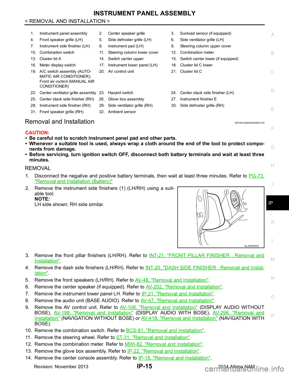
2. Remove the instrument side finishers (1) (LH/RH) using a suit-
able tool.
NOTE:
LH side shown; RH side similar.
3. Remove the front pillar finishers (LH/RH). Refer to INT-21, "FRONT PILLAR FINISHER : Removal and
Installation".
4. Remove the dash side finishers (LH/RH). Refer to INT-20, "DASH SIDE FINISHER : Removal and Instal-
lation".
5. Remove the front speakers (LH/RH). Refer to AV-48, "Removal and Installation"
.
6. Remove the center speaker (if equipped). Refer to AV-202, "Removal and Installation"
.
7. Remove the instrument lower panel LH. Refer to IP-21, "Removal and Installation"
.
8. Remove the audio unit (BASE AUDIO). Refer to AV-47, "Removal and Installation"
.
9. Remove the AV control unit. Refer to AV-108, "Removal and Installation"
(DISPLAY AUDIO WITHOUT
BOSE), AV-198, "Removal and Installation"
(DISPLAY AUDIO WITH BOSE), AV-298, "Removal and
Installation" (NAVIGATION WITHOUT BOSE) or AV-418, "Removal and Installation" ( N AV I G AT I O N W I T H
BOSE).
10. Remove the combination switch. Refer to BCS-81, "Removal and Installation"
.
11. Remove the steering wheel. Refer to ST-31, "Removal and Installation"
.
12. Remove the combination meter. Refer to MWI-82, "Removal and Installation"
.
13. Remove the glove box assembly. Refer to IP-22, "Removal and Installation"
.
14. Remove the center console assembly. Refer to IP-18, "Removal and Installation"
.
1. Instrument panel assembly 2. Center speaker grille 3. Sunload sensor (if equipped)
4. Front speaker grille (LH) 5. Side defroster grille (LH) 6. Side ventilator grille (LH)
7. Instrument side finisher (LH) 8. Instrument pad (LH) 9. Steering column upper cover
10. Combination switch 11. Steering column lower cover 12. Combination meter
13. Cluster lid A 14. Switch carrier upper 15. Switch carrier lower (if equipped)
16. Meter display switch 17. Instrument lower panel (LH) 18. Cluster lid C lower
19. A/C switch assembly (AUTO- MATIC AIR CONDITIONER);
Front air control (MANUAL AIR
CONDITIONER) 20. AV control unit 21. Cluster lid C
22. Center ventilator grille assembly 23. Hazard switch 24. Center stack side finisher (LH)
25. Center stack side finisher (RH) 26. Glove box assembly 27. Instrument finisher E
28. Instrument side finisher (RH) 29. Side ventilator grille (RH) 30. Side defroster grille (RH)
31. Front speaker grille (RH) 32. Ambient sensor
ALJIA0335ZZ
Revision: November 20132014 Altima NAM
Page 2944 of 4801
IP-18
< REMOVAL AND INSTALLATION >
CENTER CONSOLE ASSEMBLY
CENTER CONSOLE ASSEMBLY
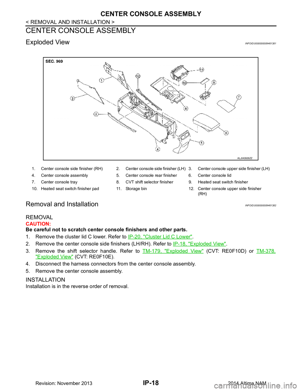
Exploded ViewINFOID:0000000009461381
Removal and InstallationINFOID:0000000009461382
REMOVAL
CAUTION:
Be careful not to scratch center console finishers and other parts.
1. Remove the cluster lid C lower. Refer to IP-20, "Cluster Lid C Lower"
.
2. Remove the center console side finishers (LH/RH). Refer to IP-18, "Exploded View"
.
3. Remove the shift selector handle. Refer to TM-179, "Exploded View"
(CVT: RE0F10D) or TM-378,
"Exploded View" (CVT: RE0F10E).
4. Disconnect the harness connectors from the center console assembly.
5. Remove the center console assembly.
INSTALLATION
Installation is in the reverse order of removal.
1. Center console side finisher (RH) 2. Center console side finisher (LH) 3. Center console upper side finisher (LH)
4. Center console assembly 5. Center console rear finisher 6. Center console lid
7. Center console tray 8. CVT shift selector finisher 9. Heated seat switch finisher
10. Heated seat switch finisher pad 11. Storage bin 12. Center console upper side finisher (RH)
ALJIA0926ZZ
Revision: November 20132014 Altima NAM
Page 2949 of 4801
CENTER CONSOLE ASSEMBLYIP-23
< UNIT DISASSEMBLY AND ASSEMBLY >
C
D E
F
G H
I
K L
M A
B
IP
N
O P
UNIT DISASSEMBLY AND ASSEMBLY
CENTER CONSOLE ASSEMBLY
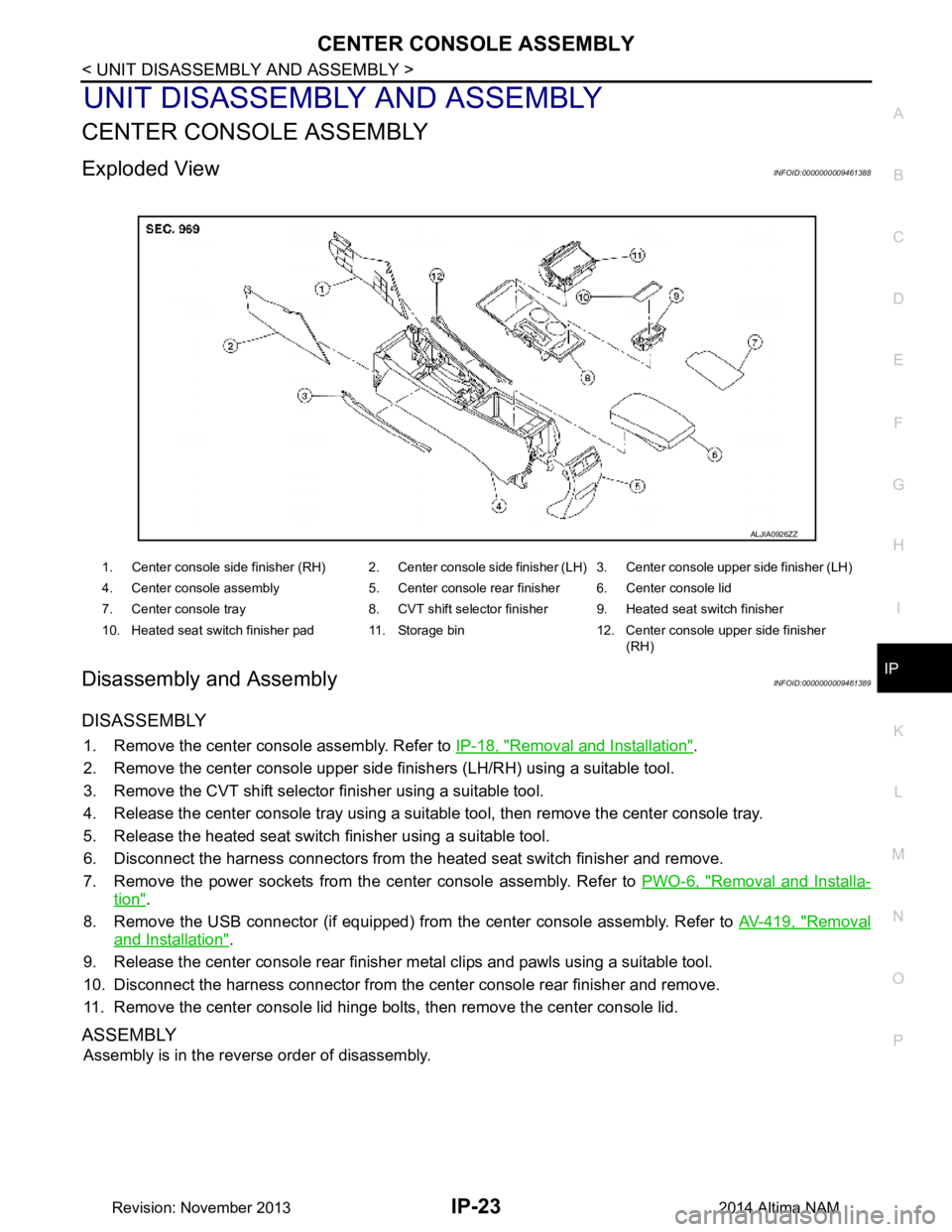
Exploded ViewINFOID:0000000009461388
Disassembly and AssemblyINFOID:0000000009461389
DISASSEMBLY
1. Remove the center console assembly. Refer to IP-18, "Removal and Installation".
2. Remove the center console upper side finishers (LH/RH) using a suitable tool.
3. Remove the CVT shift selector finisher using a suitable tool.
4. Release the center console tray using a suit able tool, then remove the center console tray.
5. Release the heated seat switch finisher using a suitable tool.
6. Disconnect the harness connectors from the heated seat switch finisher and remove.
7. Remove the power sockets from the center console assembly. Refer to PWO-6, "Removal and Installa-
tion".
8. Remove the USB connector (if equipped) from the center console assembly. Refer to AV-419, "Removal
and Installation".
9. Release the center console rear finisher metal clips and pawls using a suitable tool.
10. Disconnect the harness connector from the c enter console rear finisher and remove.
11. Remove the center console lid hinge bol ts, then remove the center console lid.
ASSEMBLY
Assembly is in the reverse order of disassembly.
1. Center console side finisher (RH) 2. Center console side finisher (LH) 3. Center console upper side finisher (LH)
4. Center console assembly 5. Center console rear finisher 6. Center console lid
7. Center console tray 8. CVT shift selector finisher 9. Heated seat switch finisher
10. Heated seat switch finisher pad 11. Storage bin 12. Center console upper side finisher (RH)
ALJIA0926ZZ
Revision: November 20132014 Altima NAM