2014 NISSAN TEANA wheel
[x] Cancel search: wheelPage 4127 of 4801

ST-24
< DTC/CIRCUIT DIAGNOSIS >
HEATED STEERING WHEEL SYSTEM
NO >> Repair or replace harness or connector.
9.CHECK HARNESS BETWEEN A/C AUTO AMP. AND HEATED STEERING WHEEL SWITCH
1. Check continuity between A/C auto amp. har ness connector terminal M152 and heated steering wheel
switch harness connector M51.
2. Check continuity between A/C auto amp. harness connector M152 and ground.
Is the inspection result normal?
YES >> GO TO 10.
NO >> Repair or replace the harness or connector.
10.CHECK HEATED STEERING WHEEL SWITCH
Check heated steering wheel switch. Refer to ST-24, "Component Inspection (Heated Steering Wheel
Switch)".
Is the inspection result normal?
YES >> Replace A/C Auto amp. Refer to HAC-102, "Removal and Installation".
NO >> Replace heated steering wheel switch.
Component Inspection (Heat ed Steering Wheel Switch)INFOID:0000000009461259
1.CHECK HEATED STEERING WHEEL SWITCH
1. Turn ignition switch OFF.
2. Remove the heated steering wheel switch connector M51.
3. Check continuity between heated st eering wheel switch terminals.
Is the inspection result normal?
YES >> GO TO 2.
NO >> Replace heated steering wheel switch.
2.CHECK HEATED STEERING WH EEL SWITCH INDICATOR LAMP
Apply 12V direct current between heated steering wheel switch terminals and check that the indicator lamp
turns ON.
Is the inspection result normal?
YES >> Inspection End.
NO >> Replace heated steering wheel switch.
Component Inspection (Heated Steering Relay)INFOID:0000000009461260
1.CHECK HEATED STEERING RELAY CONTINUITY
A/C Auto amp. Heated steering wheel switch
Continuity
Connector Terminal Connector Terminal
M152 8 M51 1 Yes
A/C Auto amp. GroundContinuity
Connector Terminal
M152 8 No
Terminal Condition Continuity
12 Switch pressed Yes
Switch released No
Te r m i n a l s Condition Indicator lamp status
+–
56 Apply 12V direct current be-
tween terminals ON
Revision: November 20132014 Altima NAMRevision: November 20132014 Altima NAM
Page 4128 of 4801
HEATED STEERING WHEEL SYSTEMST-25
< DTC/CIRCUIT DIAGNOSIS >
C
D E
F
H I
J
K L
M A
B
ST
N
O P
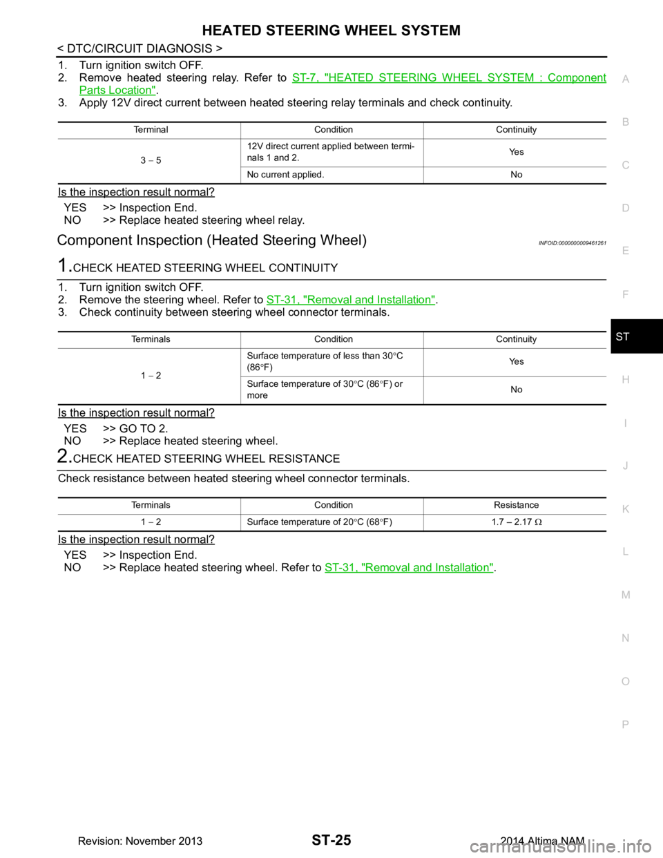
1. Turn ignition switch OFF.
2. Remove heated steering relay. Refer to ST-7, "HEATED STEERING WHEEL SYSTEM : Component
Parts Location".
3. Apply 12V direct current between heated steering relay terminals and check continuity.
Is the inspection result normal?
YES >> Inspection End.
NO >> Replace heated steering wheel relay.
Component Inspection (H eated Steering Wheel)INFOID:0000000009461261
1.CHECK HEATED STEERING WHEEL CONTINUITY
1. Turn ignition switch OFF.
2. Remove the steering wheel. Refer to ST-31, "Removal and Installation"
.
3. Check continuity between steering wheel connector terminals.
Is the inspection result normal?
YES >> GO TO 2.
NO >> Replace heated steering wheel.
2.CHECK HEATED STEERING WHEEL RESISTANCE
Check resistance between heated steering wheel connector terminals.
Is the inspection result normal?
YES >> Inspection End.
NO >> Replace heated steering wheel. Refer to ST-31, "Removal and Installation"
.
Terminal Condition Continuity
3 − 5 12V direct current applied between termi-
nals 1 and 2. Ye s
No current applied. No
Terminals Condition Continuity
1 − 2 Surface temperature of less than 30
°C
(86 °F) Ye s
Surface temperature of 30 °C (86 °F) or
more No
Terminals Condition Resistance
1 − 2 Surface temperature of 20 °C (68 °F) 1.7 – 2.17 Ω
Revision: November 20132014 Altima NAMRevision: November 20132014 Altima NAM
Page 4129 of 4801

ST-26
< DTC/CIRCUIT DIAGNOSIS >
HEATED STEERING WHEEL SWITCH INDICATOR LAMP
HEATED STEERING WHEEL SWITCH INDICATOR LAMP
Component Function CheckINFOID:0000000009461262
1.CHECK HEATED STEERING WHEEL SWITCH INDICATOR LAMP
1. Turn ignition switch ON.
2. Turn heated steering wheel switch ON. Observe indicator.
3. Turn heated steering wheel switch OFF. Observe indicator.
Does heated steering wheel switch indicator lamp turn ON and then OFF?
YES >> Inspection End.
NO >> Go to ST-26, "Diagnosis Procedure"
.
Diagnosis ProcedureINFOID:0000000009461263
1.CHECK POWER CIRCUIT
1. Turn ignition switch OFF.
2. Remove the heated steering wheel switch.
3. Turn ignition switch ON.
4. Check voltage between heated steering wheel switch harness connector M51.
Is the inspection result normal?
YES >> GO TO 2.
NO >> GO TO 3.
2.CHECK GROUND CIRCUIT
1. Turn ignition switch OFF.
2. Disconnect heated steering wheel switch connector.
3. Check continuity between heated steering wheel switch harness connector terminal M51 and ground.
Is the inspection result normal?
YES >> GO TO 3.
NO >> Repair or replace the harness or connectors.
3.CHECK HARNESS BETWEEN HEATED STEERING RELAY AND HEATED STEERING WHEEL SWITCH
1. Disconnect heated steering relay connector.
2. Check continuity between heated steering rela y harness connector terminal M90 and heated steering
wheel switch harness connector M51.
3. Check continuity between heated steer ing relay harness connector M90 and ground.
Is the inspection result normal?
YES >> GO TO 4.
NO >> Repair or replace harness or connectors.
Connector Te r m i n a l
Voltage (Approx.)
+-
M51 1 2 Battery voltage
Connector Terminal GroundContinuity
M51 6 Yes
Heated steering relay Heated steering wheel switch Continuity
Connector Terminal Connector Terminal
M90 5 M51 5 Yes
Connector Terminal GroundContinuity
M90 5 No
Revision: November 20132014 Altima NAMRevision: November 20132014 Altima NAM
Page 4130 of 4801
HEATED STEERING WHEEL SWITCH INDICATOR LAMPST-27
< DTC/CIRCUIT DIAGNOSIS >
C
D E
F
H I
J
K L
M A
B
ST
N
O P
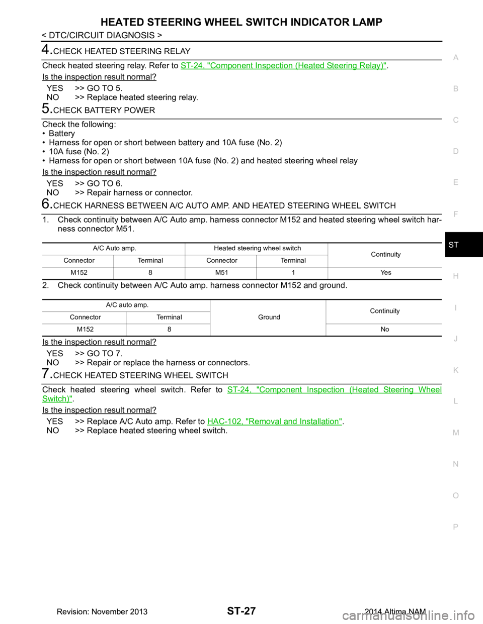
4.CHECK HEATED STEERING RELAY
Check heated steering relay. Refer to ST-24, "Component Inspection (Heated Steering Relay)"
.
Is the inspection result normal?
YES >> GO TO 5.
NO >> Replace heated steering relay.
5.CHECK BATTERY POWER
Check the following:
•Battery
• Harness for open or short between battery and 10A fuse (No. 2)
• 10A fuse (No. 2)
• Harness for open or short between 10A fuse (No. 2) and heated steering wheel relay
Is the inspection result normal?
YES >> GO TO 6.
NO >> Repair harness or connector.
6.CHECK HARNESS BETWEEN A/C AUTO AMP. AND HEATED STEERING WHEEL SWITCH
1. Check continuity between A/C Auto amp. harne ss connector M152 and heated steering wheel switch har-
ness connector M51.
2. Check continuity between A/C Auto amp. harness connector M152 and ground.
Is the inspection result normal?
YES >> GO TO 7.
NO >> Repair or replace the harness or connectors.
7.CHECK HEATED STEERING WHEEL SWITCH
Check heated steering wheel switch. Refer to ST-24, "Component Inspection (Heated Steering Wheel
Switch)".
Is the inspection result normal?
YES >> Replace A/C Auto amp. Refer to HAC-102, "Removal and Installation".
NO >> Replace heated steering wheel switch.
A/C Auto amp. Heated steering wheel switch Continuity
Connector Terminal Connector Terminal
M152 8 M51 1 Yes
A/C auto amp. GroundContinuity
Connector Terminal
M152 8 No
Revision: November 20132014 Altima NAMRevision: November 20132014 Altima NAM
Page 4131 of 4801

ST-28
< SYMPTOM DIAGNOSIS >
STEERING COLUMN
SYMPTOM DIAGNOSIS
STEERING COLUMN
Symptom TableINFOID:0000000009461264
HEATED STEERING WHEEL
Symptom Inspection item
Heated steering wheel system inoperative Refer to ST-22, "Diagnosis Procedure"
.
Heated steering wheel switch indicator lamp inoperative Refer to ST-26, "Diagnosis Procedure"
.
Revision: November 20132014 Altima NAMRevision: November 20132014 Altima NAM
Page 4132 of 4801
NOISE, VIBRATION AND HARSHNESS (NVH) TROUBLESHOOTINGST-29
< SYMPTOM DIAGNOSIS >
C
D E
F
H I
J
K L
M A
B
ST
N
O P
NOISE, VIBRATION AND HARSHN ESS (NVH) TROUBLESHOOTING
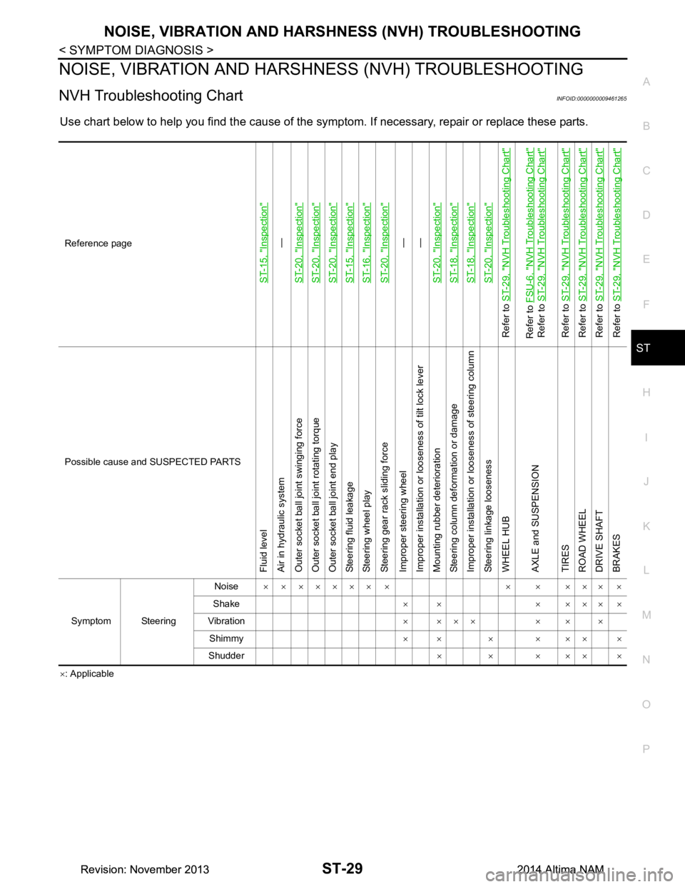
NVH Troubleshooting ChartINFOID:0000000009461265
Use chart below to help you find the cause of the symptom. If necessary, repair or replace these parts.
×: Applicable
Reference page
ST-15, "Inspection"
—
ST-20, "Inspection"
ST-20, "Inspection"ST-20, "Inspection"ST-15, "Inspection"ST-16, "Inspection"ST-20, "Inspection"
—
—
ST-20, "Inspection"
ST-18, "Inspection"ST-18, "Inspection"ST-20, "Inspection"
Refer to ST-29, "NVH Troubleshooting Chart"Refer to FSU-6, "NVH Troubleshooting Chart"
Refer to ST-29, "NVH Troubleshooting Chart"
Refer to ST-29, "NVH Troubleshooting Chart"
Refer to ST-29, "NVH Troubleshooting Chart"
Refer to ST-29, "NVH Troubleshooting Chart"
Refer to ST-29, "NVH Troubleshooting Chart"
Possible cause and SUSPECTED PARTS
Fluid level
Air in hydraulic system
Outer socket ball joint swinging force
Outer socket ball joint rotating torque
Outer socket ball joint end play
Steering fluid leakage
Steering wheel play
Steering gear rack sliding force
Improper steering wheel
Improper installation or looseness of tilt lock lever
Mounting rubber deterioration
Steering column deformation or damage
Improper installation or looseness of steering column
Steering linkage looseness
WHEEL HUB
AXLE and SUSPENSION
TIRES
ROAD WHEEL
DRIVE SHAFT
BRAKES
Symptom Steering Noise
× × ××××× × × × ××× ×
Shake ×× ×××××
Vibration × ××× × × ×
Shimmy ×× × ××× ×
Shudder ××××××
Revision: November 20132014 Altima NAMRevision: November 20132014 Altima NAM
Page 4133 of 4801
ST-30
< PERIODIC MAINTENANCE >
POWER STEERING FLUID
PERIODIC MAINTENANCE
POWER STEERING FLUID
Draining and RefillingINFOID:0000000009461266
DRAINING
1. Disconnect the high and low pressure piping from power steering gear.
2. Drain power steering fluid into a suitable container.
REFILLING
1. Fill power steering reservoir while checking power steering fluid level.
2. Bleed air from power steering hydraulic system. Refer to ST-30, "Air Bleeding Hydraulic System"
.
3. Check for power steering fluid leaks.
Air Bleeding Hydraulic SystemINFOID:0000000009461267
AIR BLEEDING HYDRAULIC SYSTEM
If air bleeding is not complete, excessive noise in the power steering oil pump will be present.
1. Make sure engine is off.
2. Turn the steering wheel from the full right stop pos ition and then to full left stop position several times.
Repeat until bubbles are no longer being generated in the reservoir.
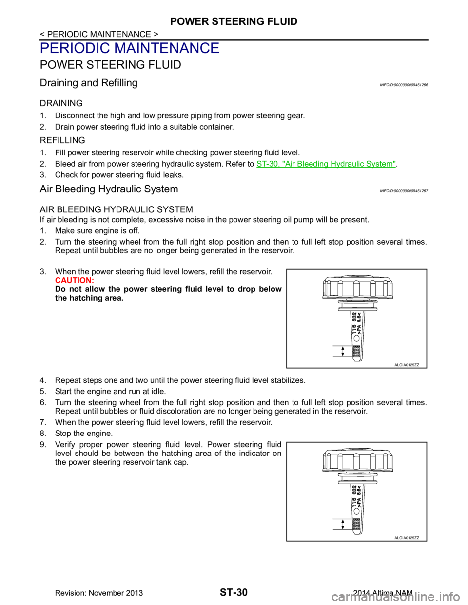
3. When the power steering fluid level lowers, refill the reservoir. CAUTION:
Do not allow the power steerin g fluid level to drop below
the hatching area.
4. Repeat steps one and two until the power steering fluid level stabilizes.
5. Start the engine and run at idle.
6. Turn the steering wheel from the full right stop pos ition and then to full left stop position several times.
Repeat until bubbles or fluid discoloration are no longer being generated in the reservoir.
7. When the power steering fluid level lowers, refill the reservoir.
8. Stop the engine.
9. Verify proper power steering fluid level. Power steering fluid level should be between the hatching area of the indicator on
the power steering reservoir tank cap.
ALGIA0125ZZ
ALGIA0125ZZ
Revision: November 20132014 Altima NAMRevision: November 20132014 Altima NAM
Page 4134 of 4801
STEERING WHEELST-31
< REMOVAL AND INSTALLATION >
C
D E
F
H I
J
K L
M A
B
ST
N
O P
REMOVAL AND INSTALLATION
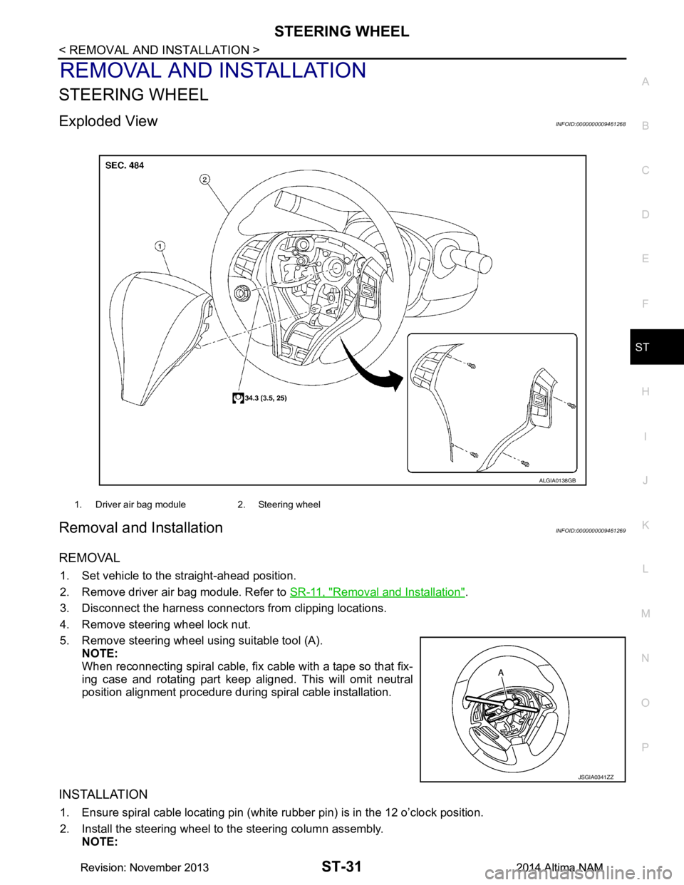
STEERING WHEEL
Exploded ViewINFOID:0000000009461268
Removal and InstallationINFOID:0000000009461269
REMOVAL
1. Set vehicle to the straight-ahead position.
2. Remove driver air bag module. Refer to SR-11, "Removal and Installation"
.
3. Disconnect the harness connectors from clipping locations.
4. Remove steering wheel lock nut.
5. Remove steering wheel using suitable tool (A). NOTE:
When reconnecting spiral cable, fix cable with a tape so that fix-
ing case and rotating part keep aligned. This will omit neutral
position alignment procedure during spiral cable installation.
INSTALLATION
1. Ensure spiral cable locating pin (white rubber pin) is in the 12 o’clock position.
2. Install the steering wheel to the steering column assembly. NOTE:
1. Driver air bag module 2. Steering wheel
ALGIA0138GB
JSGIA0341ZZ
Revision: November 20132014 Altima NAMRevision: November 20132014 Altima NAM