2014 NISSAN TEANA wheel
[x] Cancel search: wheelPage 4186 of 4801

STEERING WHEEL TURNING FORCE IS HEAVY OR LIGHTSTC-35
< SYMPTOM DIAGNOSIS >
C
D E
F
H I
J
K L
M A
B
STC
N
O P
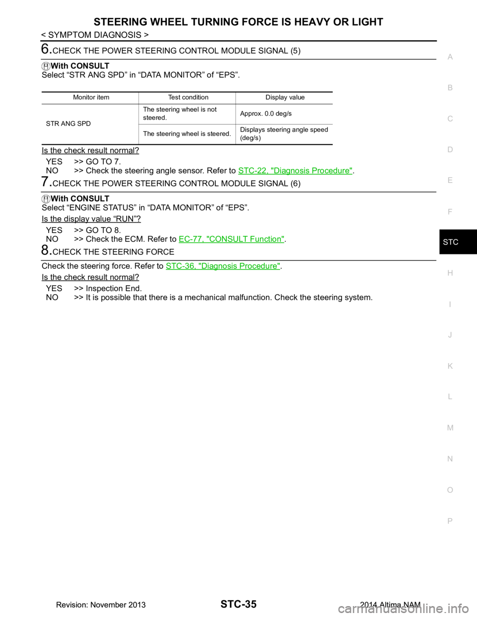
6.CHECK THE POWER STEERING CONTROL MODULE SIGNAL (5)
With CONSULT
Select “STR ANG SPD” in “DATA MONITOR” of “EPS”.
Is the check result normal?
YES >> GO TO 7.
NO >> Check the steering angle sensor. Refer to STC-22, "Diagnosis Procedure"
.
7.CHECK THE POWER STEERING CONTROL MODULE SIGNAL (6)
With CONSULT
Select “ENGINE STATUS” in “DATA MONITOR” of “EPS”.
Is the display value
“RUN”?
YES >> GO TO 8.
NO >> Check the ECM. Refer to EC-77, "CONSULT Function"
.
8.CHECK THE STEERING FORCE
Check the steering force. Refer to STC-36, "Diagnosis Procedure"
.
Is the check result normal?
YES >> Inspection End.
NO >> It is possible that there is a mechani cal malfunction. Check the steering system.
Monitor item Test condition Display value
STR ANG SPD The steering wheel is not
steered. Approx. 0.0 deg/s
The steering wheel is steered. Displays steering angle speed
(deg/s)
Revision: November 20132014 Altima NAMRevision: November 20132014 Altima NAM
Page 4187 of 4801

STC-36
< SYMPTOM DIAGNOSIS >
UNBALANCE STEERING WHEEL TURNING FORCE AND RETURN BETWEEN
RIGHT AND LEFT
UNBALANCE STEERING WHEEL TU RNING FORCE AND RETURN BE-
TWEEN RIGHT AND LEFT
Diagnosis ProcedureINFOID:0000000009460377
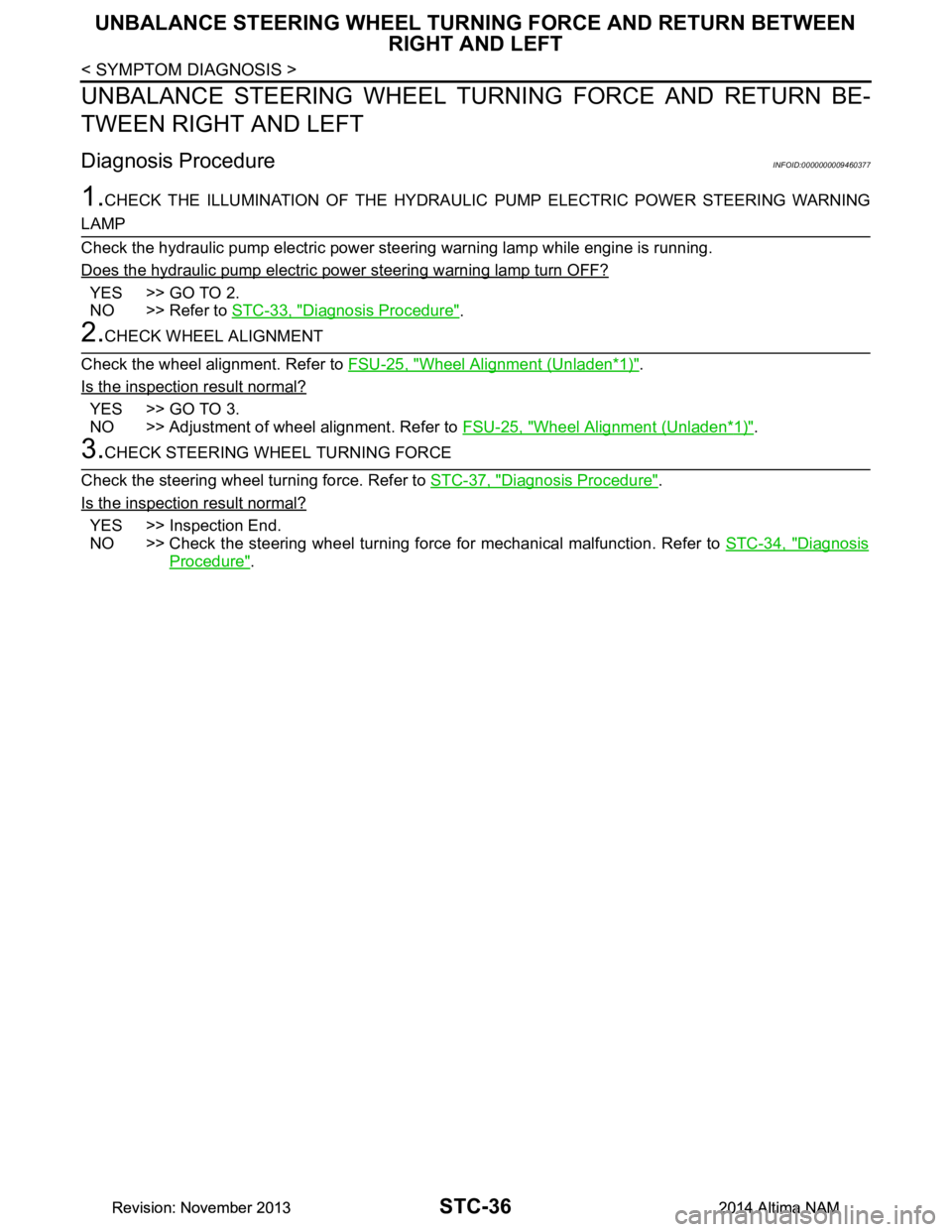
1.CHECK THE ILLUMINATION OF THE HYDRAULIC PUMP ELECTRIC POWER STEERING WARNING
LAMP
Check the hydraulic pump electric power steering warning lamp while engine is running.
Does the hydraulic pump electric power steering warning lamp turn OFF?
YES >> GO TO 2.
NO >> Refer to STC-33, "Diagnosis Procedure"
.
2.CHECK WHEEL ALIGNMENT
Check the wheel alignment. Refer to FSU-25, "Wheel Alignment (Unladen*
1)".
Is the inspection result normal?
YES >> GO TO 3.
NO >> Adjustment of wheel alignment. Refer to FSU-25, "Wheel Alignment (Unladen*
1)".
3.CHECK STEERING WHEEL TURNING FORCE
Check the steering wheel turning force. Refer to STC-37, "Diagnosis Procedure"
.
Is the inspection result normal?
YES >> Inspection End.
NO >> Check the steering wheel turning force for mechanical malfunction. Refer to STC-34, "Diagnosis
Procedure".
Revision: November 20132014 Altima NAMRevision: November 20132014 Altima NAM
Page 4188 of 4801

UNBALANCE STEERING WHEEL TURNING FORCE (TORQUE VARIATION)
STC-37
< SYMPTOM DIAGNOSIS >
C
D E
F
H I
J
K L
M A
B
STC
N
O P
UNBALANCE STEERING WHEEL TU RNING FORCE (TORQUE VARIA-
TION)
Diagnosis ProcedureINFOID:0000000009460378
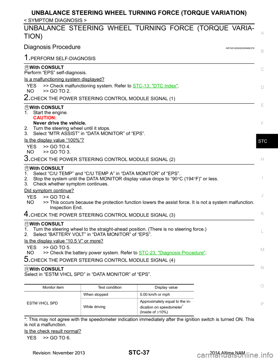
1.PERFORM SELF-DIAGNOSIS
With CONSULT
Perform “EPS” self-diagnosis.
Is a malfunctioning system displayed?
YES >> Check malfunctioning system. Refer to STC-13, "DTC Index".
NO >> GO TO 2.
2.CHECK THE POWER STEERING CONTROL MODULE SIGNAL (1)
With CONSULT
1. Start the engine. CAUTION:
Never drive the vehicle.
2. Turn the steering wheel until it stops.
3. Select “MTR ASSIST” in “DATA MONITOR” of “EPS”.
Is the display value
“100%”?
YES >> GO TO 4.
NO >> GO TO 3.
3.CHECK THE POWER STEERING CONTROL MODULE SIGNAL (2)
With CONSULT
1. Select “C/U TEMP” and “C/U TEMP A” in “DATA MONITOR” of “EPS”.
2. Stop the system until the DATA MONITOR display value drops to “90 °C (194 °F)” or less.
3. Check whether symptom continues.
Did symptom continue?
YES >> GO TO 4.
NO >> This occurs because the protection function lowers the assist force. It is not a system malfunction.
Inspection End.
4.CHECK THE POWER STEERING CONTROL MODULE SIGNAL (3)
With CONSULT
1. Turn the steering wheel to the straight -ahead position. (There is no steering force.)
2. Select “BATTERY VOLT” in “DATA MONITOR” of “EPS”.
Is the display value
“10.5 V” or more?
YES >> GO TO 5.
NO >> Check the battery power system. Refer to STC-23, "Diagnosis Procedure"
.
5.CHECK THE POWER STEERING CONTROL MODULE SIGNAL (4)
With CONSULT
Select in “ESTM VHCL SPD” in “DATA MONITOR” of “EPS”.
*: This may not agree with the speedometer indication immediately after the ignition switch is turned ON. This
is not a malfunction.
Is the check result normal?
YES >> GO TO 6.
Monitor item Test condition Display value
ESTM VHCL SPD When stopped 0.00 km/h or mph
While driving Approximately equal to the in-
dication on speedometer
*
(Inside of ±10%)
Revision: November 20132014 Altima NAMRevision: November 20132014 Altima NAM
Page 4189 of 4801

STC-38
< SYMPTOM DIAGNOSIS >
UNBALANCE STEERING WHEEL TURNING FORCE (TORQUE VARIATION)
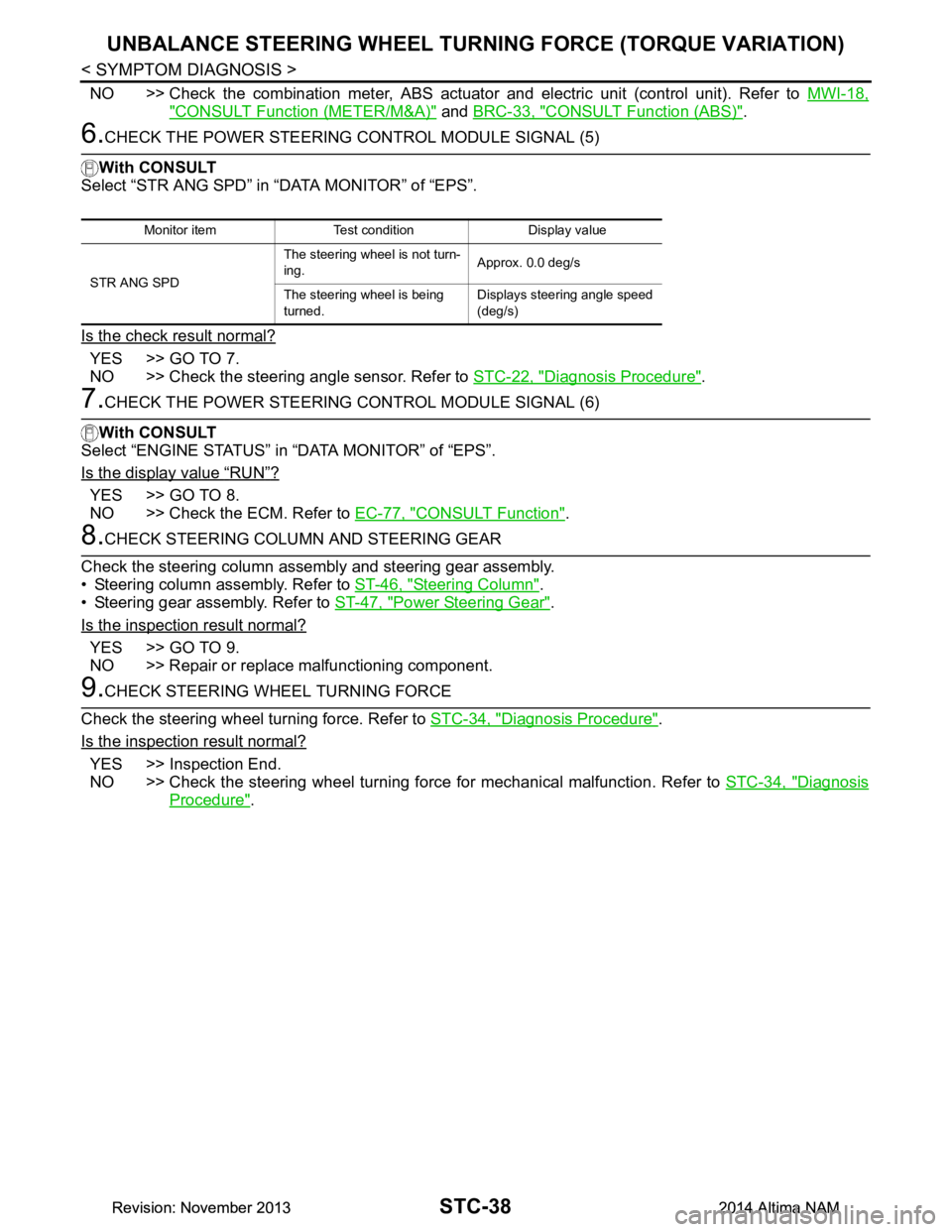
NO >> Check the combination meter, ABS actuator and electric unit (control unit). Refer to MWI-18,
"CONSULT Function (METER/M&A)" and BRC-33, "CONSULT Function (ABS)".
6.CHECK THE POWER STEERING CONTROL MODULE SIGNAL (5)
With CONSULT
Select “STR ANG SPD” in “DATA MONITOR” of “EPS”.
Is the check result normal?
YES >> GO TO 7.
NO >> Check the steering angle sensor. Refer to STC-22, "Diagnosis Procedure"
.
7.CHECK THE POWER STEERING CONTROL MODULE SIGNAL (6)
With CONSULT
Select “ENGINE STATUS” in “DATA MONITOR” of “EPS”.
Is the display value
“RUN”?
YES >> GO TO 8.
NO >> Check the ECM. Refer to EC-77, "CONSULT Function"
.
8.CHECK STEERING COLUMN AND STEERING GEAR
Check the steering column assembly and steering gear assembly.
• Steering column assembly. Refer to ST-46, "Steering Column"
.
• Steering gear assembly. Refer to ST-47, "Power Steering Gear"
.
Is the inspection result normal?
YES >> GO TO 9.
NO >> Repair or replace malfunctioning component.
9.CHECK STEERING WHEEL TURNING FORCE
Check the steering wheel turning force. Refer to STC-34, "Diagnosis Procedure"
.
Is the inspection result normal?
YES >> Inspection End.
NO >> Check the steering wheel turning force for mechanical malfunction. Refer to STC-34, "Diagnosis
Procedure".
Monitor item Test condition Display value
STR ANG SPD The steering wheel is not turn-
ing. Approx. 0.0 deg/s
The steering wheel is being
turned. Displays steering angle speed
(deg/s)
Revision: November 20132014 Altima NAMRevision: November 20132014 Altima NAM
Page 4249 of 4801
![NISSAN TEANA 2014 Service Manual
TM-34
< SYSTEM DESCRIPTION >[CVT: RE0F10D]
SYSTEM
CVT CONTROL SYSTEM : Protection Control
INFOID:0000000009463989
The TCM becomes the protection control status temporar ily to protect the safety wh NISSAN TEANA 2014 Service Manual
TM-34
< SYSTEM DESCRIPTION >[CVT: RE0F10D]
SYSTEM
CVT CONTROL SYSTEM : Protection Control
INFOID:0000000009463989
The TCM becomes the protection control status temporar ily to protect the safety wh](/manual-img/5/57390/w960_57390-4248.png)
TM-34
< SYSTEM DESCRIPTION >[CVT: RE0F10D]
SYSTEM
CVT CONTROL SYSTEM : Protection Control
INFOID:0000000009463989
The TCM becomes the protection control status temporar ily to protect the safety when the safety of TCM and
transmission is lost. It automatically returns to the normal status if the safety is secured.
The TCM has the following protection control.
CONTROL FOR WHEEL SPIN
TORQUE IS REDUCED WHEN DRIVING WITH THE REVERSE GEAR
CONTROL WHEN FLUID TEMPERATURE IS HIGH
P2813 • Selector shock is large
•Start is slow
• Acceleration is slow
• Vehicle speed is not increased When a malfunction occurs on the low oil pressure side
• Selector shock is large When a malfunction occurs on the high oil pressure side
P2814 • Selector shock is large —
P2815 • Selector shock is large —
U0073 • Selector shock is large
•Start is slow
• Acceleration is slow
• Lock-up is not performed —
U0100 • Selector shock is large
•Start is slow
• Acceleration is slow
• Lock-up is not performed —
U0140 • Not changed from normal driving —
U0141 • Not changed from normal driving —
U0155 • Not changed from normal driving —
U0300 • Selector shock is large
•Start is slow
• Acceleration is slow
• Lock-up is not performed —
U1000 • Not changed from normal driving — U1117 • Not changed from normal driving — DTC Vehicle behavior Conditions of vehicle
Control
When a wheel spin is detected, the engine output and gear ratio are limited and the line pressure is increased.
Limits engine output when a wheel spin occurs in any of right and left drive wheels.
Vehicle behavior in
control If the accelerator is kept depressing during wheel spin, the engine revolution and vehicle speed are limited to
a certain degree.
Normal retu rn condi-
tion Wheel spin convergence returns the control to the normal control.
Control Engine output is controlled according to a vehicle speed while reversing the vehicle.
Vehicle behavior in
control Power performance may be lowered while reversing the vehicle.
Normal retu rn condi-
tion Torque returns to normal by positioning the selector lever in a range other than “R” position.
Control
When the CVT fluid temperature is high, the gear shift permission maximum revolution and the maximum
torque are reduced than usual to prevent increase of the oil temperature.
Vehicle behavior in
control Power performance may be lowered, compared to normal control.
Normal retu rn condi-
tion The control returns to the normal control when CVT fluid temperature is lowered.
Revision: November 20132014 Altima NAMRevision: November 20132014 Altima NAM
Page 4274 of 4801
![NISSAN TEANA 2014 Service Manual
TCM
TM-59
< ECU DIAGNOSIS INFORMATION > [CVT: RE0F10D]
C
EF
G H
I
J
K L
M A
B
TM
N
O P
Protection Control INFOID:0000000009464003
The TCM becomes the protection control status temporar ily to protec NISSAN TEANA 2014 Service Manual
TCM
TM-59
< ECU DIAGNOSIS INFORMATION > [CVT: RE0F10D]
C
EF
G H
I
J
K L
M A
B
TM
N
O P
Protection Control INFOID:0000000009464003
The TCM becomes the protection control status temporar ily to protec](/manual-img/5/57390/w960_57390-4273.png)
TCM
TM-59
< ECU DIAGNOSIS INFORMATION > [CVT: RE0F10D]
C
EF
G H
I
J
K L
M A
B
TM
N
O P
Protection Control INFOID:0000000009464003
The TCM becomes the protection control status temporar ily to protect the safety when the safety of TCM and
transmission is lost. It automatically returns to the normal status if the safety is secured.
The TCM has the following protection control.
CONTROL FOR WHEEL SPIN
TORQUE IS REDUCED WHEN DRIVING WITH THE REVERSE GEAR
CONTROL WHEN FLUID TEMPERATURE IS HIGH
REVERSE PROHIBIT CONTROL
DTC Inspection Priority ChartINFOID:0000000009464004
If multiple malfunction codes are detected at the same time, check each code according to the DTC check pri-
ority list below.
Control When a wheel spin is detected, the engine output and gear ratio are limited and the line pressure is increased.
Limits engine output when a wheel spin occurs in any of right and left drive wheels.
Vehicle behavior in
control If the accelerator is kept depressing during wheel spin, the engine revolution and vehicle speed are limited to
a certain degree.
Normal return condi-
tion Wheel spin convergence returns the control to the normal control.
Control Engine output is controlled according to a vehicle speed while reversing the vehicle.
Vehicle behavior in
control Power performance may be lowered while reversing the vehicle.
Normal return condi-
tion Torque returns to normal by positioning the sele
ctor lever in a range other than “R” position.
Control When the CVT fluid temperature is high, the gear shift permission maximum revolution and the maximum
torque are reduced than usual to prevent increase of the oil temperature.
Vehicle behavior in
control Power performance may be lowered, compared to normal control.
Normal return condi-
tion The control returns to the normal control when CVT fluid temperature is lowered.
ControlThe reverse brake is controlled to avoid becoming engaged when the selector lever is set in “R” position while
driving in forward direction at more than the specified speed.
Vehicle behavior in
control If the selector lever is put at “R” position when driving with the forward gear, the gear becomes neutral, not
reverse.
Normal return condi-
tion The control returns to normal control when the vehicle is driven at low speeds. (The reverse brake becomes
engaged.)
Priority DTC (Diagnostic Trouble Code) Reference
1 P0863 CONTROL UNIT (CAN)
TM-143, "DTC Logic"
U0073 COMM BUS A OFF TM-88, "DTC Logic"
U0100 LOST COMM (ECM A)TM-89, "DTC Logic"
U0140 LOST COMM (BCM)TM-90, "DTC Logic"
U0141 LOST COMM (BCM A)TM-91, "DTC Logic"
U0155 LOST COMM (IPC)TM-92, "DTC Logic"
U0300 CAN COMM DATA TM-93, "DTC Logic"
U1000 CAN COMM CIRCTM-94, "DTC Logic"
U1117 LOST COMM (ABS)TM-95, "DTC Logic"
Revision: November 20132014 Altima NAMRevision: November 20132014 Altima NAM
Page 4302 of 4801
![NISSAN TEANA 2014 Service Manual
CVT POSITIONTM-87
< BASIC INSPECTION > [CVT: RE0F10D]
C
EF
G H
I
J
K L
M A
B
TM
N
O P
CVT POSITION
InspectionINFOID:0000000009464017
1. Turn ON the ignition switch with the shift selector at the “ NISSAN TEANA 2014 Service Manual
CVT POSITIONTM-87
< BASIC INSPECTION > [CVT: RE0F10D]
C
EF
G H
I
J
K L
M A
B
TM
N
O P
CVT POSITION
InspectionINFOID:0000000009464017
1. Turn ON the ignition switch with the shift selector at the “](/manual-img/5/57390/w960_57390-4301.png)
CVT POSITIONTM-87
< BASIC INSPECTION > [CVT: RE0F10D]
C
EF
G H
I
J
K L
M A
B
TM
N
O P
CVT POSITION
InspectionINFOID:0000000009464017
1. Turn ON the ignition switch with the shift selector at the “P” position.
2. Press the shift selector button with the brake pedal depressed, and confirm that the shift selector can be
moved to positions other than “P”. Also confirm that movement is not allowed from the “P” position to other
position without depressing the brake pedal.
3. Move the shift selector and check for “excessive effort”, “sticking”, “noise” or “rattle”.
4. Confirm that shift selector stops at each position with the feel of engagement when it is moved through all
the positions. Check whether or not the actual position the shift selector is in matches the position shown
by the transaxle body.
5. Make sure that the shift selector is moved to all the shift posi- tions in the manner shown.
• (A): Press shift selector button to operate shift selector, while depressing the brake pedal.
• (B): Press shift selector button to operate shift selector.
• (C): Shift selector can be operated without pressing the shift selector button.
6. When the shift selector button is pressed without applying for- ward/backward force to the shift selector at “P”, “R”, “N”, “D” or
“Ds” positions, there should be no “sticking” on the shift selector
button operation.
7. Check that the back-up lamps do not illuminate when the shift selector is in the “P” position.
8. Check that the engine can be started with the sh ift selector in the “P” and “N” positions only.
9. Check that the transaxle is locked completely when the shift selector is in the “P” position.
AdjustmentINFOID:0000000009464018
1. Shift the shift selector to the “P” position.
CAUTION:
Turn wheels at least a quarter turn and be certain the park position mechanism is fully engaged.
2. Loosen the control cable nut. CAUTION:
Do not apply force to the manual lever.
3. Position the manual lever in the “P” position.
4. Tighten the control cable nut to specified torque. Refer to TM-
181, "Exploded View".
CAUTION:
Hold manual lever when tightening.
AWDIA1019ZZ
JSDIA1875ZZ
Revision: November 20132014 Altima NAMRevision: November 20132014 Altima NAM
Page 4451 of 4801
![NISSAN TEANA 2014 Service Manual
TM-236
< SYSTEM DESCRIPTION >[CVT: RE0F10E]
SYSTEM
CVT CONTROL SYSTEM : Protection Control
INFOID:0000000009464206
The TCM becomes the protection control status temporar ily to protect the safety w NISSAN TEANA 2014 Service Manual
TM-236
< SYSTEM DESCRIPTION >[CVT: RE0F10E]
SYSTEM
CVT CONTROL SYSTEM : Protection Control
INFOID:0000000009464206
The TCM becomes the protection control status temporar ily to protect the safety w](/manual-img/5/57390/w960_57390-4450.png)
TM-236
< SYSTEM DESCRIPTION >[CVT: RE0F10E]
SYSTEM
CVT CONTROL SYSTEM : Protection Control
INFOID:0000000009464206
The TCM becomes the protection control status temporar ily to protect the safety when the safety of TCM and
transmission is lost. It automatically returns to the normal status if the safety is secured.
The TCM has the following protection control.
CONTROL FOR WHEEL SPIN
TORQUE IS REDUCED WHEN DRIVING WITH THE REVERSE GEAR
CONTROL WHEN FLUID TEMPERATURE IS HIGH
P2813 • Selector shock is large
•Start is slow
• Acceleration is slow
• Vehicle speed is not increased When a malfunction occurs on the low oil pressure side
• Selector shock is large When a malfunction occurs on the high oil pressure side
P2814 • Selector shock is large —
P2815 • Selector shock is large —
U0073 • Selector shock is large
•Start is slow
• Acceleration is slow
• Lock-up is not performed —
U0100 • Selector shock is large
•Start is slow
• Acceleration is slow
• Lock-up is not performed —
U0140 • Not changed from normal driving —
U0141 • Not changed from normal driving —
U0155 • Not changed from normal driving —
U0300 • Selector shock is large
•Start is slow
• Acceleration is slow
• Lock-up is not performed —
U1000 • Not changed from normal driving — U1117 • Not changed from normal driving — DTC Vehicle behavior Conditions of vehicle
Control
When a wheel spin is detected, the engine output and gear ratio are limited and the line pressure is increased.
Limits engine output when a wheel spin occurs in any of right and left drive wheels.
Vehicle behavior in
control If the accelerator is kept depressing during wheel spin, the engine revolution and vehicle speed are limited to
a certain degree.
Normal retu rn condi-
tion Wheel spin convergence returns the control to the normal control.
Control Engine output is controlled according to a vehicle speed while reversing the vehicle.
Vehicle behavior in
control Power performance may be lowered while reversing the vehicle.
Normal retu rn condi-
tion Torque returns to normal by positioning the selector lever in a range other than “R” position.
Control
When the CVT fluid temperature is high, the gear shift permission maximum revolution and the maximum
torque are reduced than usual to prevent increase of the oil temperature.
Vehicle behavior in
control Power performance may be lowered, compared to normal control.
Normal retu rn condi-
tion The control returns to the normal control when CVT fluid temperature is lowered.
Revision: November 20132014 Altima NAMRevision: November 20132014 Altima NAM