2014 NISSAN TEANA wheel
[x] Cancel search: wheelPage 3999 of 4801
SRC-6
< SYSTEM DESCRIPTION >
COMPONENT PARTS
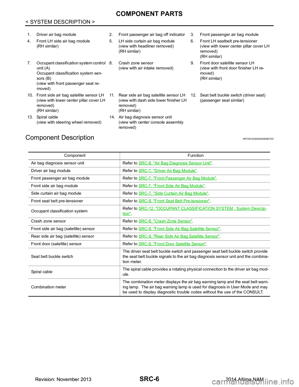
Component Description
INFOID:0000000009460705
1. Driver air bag module 2. Front passenger air bag off indicator 3. Front passenger air bag module
4. Front LH side air bag module (RH similar) 5. LH side curtain air bag module
(view with headliner removed)
(RH similar) 6. Front LH seatbelt pre-tensioner
(view with lower cent er pillar cover LH
removed)
(RH similar)
7. Occupant classification system control unit (A)
Occupant classification system sen-
sors (B)
(view with front passenger seat re-
moved) 8. Crash zone sensor
(view with air intake removed) 9. Front door satellite sensor LH
(view with front door finisher LH re-
moved)
(RH similar)
10. Front side air bag satellite sensor LH (view with lower cent er pillar cover LH
removed)
(RH similar) 11. Rear side air bag satellite sensor LH
(view with dash side lower finisher LH
removed)
(RH similar) 12. Seat belt buckle switch (driver seat)
(passenger seat similar)
13. Spiral cable (view with steeri ng wheel removed) 14. Air bag diagnosis sensor unit
(view with center console assembly
removed)
Component Function
Air bag diagnosis sensor unit Refer to SRC-8, "Air Bag Diagnosis Sensor Unit"
.
Driver air bag module Refer to SRC-7, "Driver Air Bag Module"
.
Front passenger air bag module Refer to SRC-7, "Front Passenger Air Bag Module"
.
Front side air bag module Refer to SRC-7, "Front Side Air Bag Module"
.
Side curtain air bag module Refer to SRC-7, "Side Curtain Air Bag Module"
.
Front seat belt pre-tensioner Refer to SRC-8, "Front Seat Belt Pre-tensioner"
.
Occupant classification system Refer to
SRC-12, "OCCUPANT CLASSIFICATION SYSTEM : System Descrip-
tion".
Crash zone sensor Refer to SRC-8, "Crash Zone Sensor"
.
Front side air bag (satellite) sensor Refer to SRC-8, "Front Side Air Bag Satellite Sensor"
.
Rear side air bag (satellite) sensor Refer to SRC-9, "Rear Side Air Bag Satellite Sensor"
.
Front door (satellite) sensor Refer to SRC-9, "Front Door Satellite Sensor"
.
Seat belt buckle switch The driver seat belt buckle switch and passenger seat belt buckle switch provide
the seat belt buckle signals to the air bag diagnosis sensor unit and the combina-
tion meter.
Sp iral c ab le The spiral cable provides a rotating physical connection to the driver air bag mod-
ule.
Combination meter The combination meter displays the air bag warning lamp and the seat belt warn-
ing lamp. The air bag warning lamp is used for diagnosis in User Mode and may
be used to display diagnostic trouble codes without the use of the CONSULT.
Revision: November 20132014 Altima NAMRevision: November 20132014 Altima NAM
Page 4000 of 4801
COMPONENT PARTSSRC-7
< SYSTEM DESCRIPTION >
C
D E
F
G
I
J
K L
M A
B
SRC
N
O P
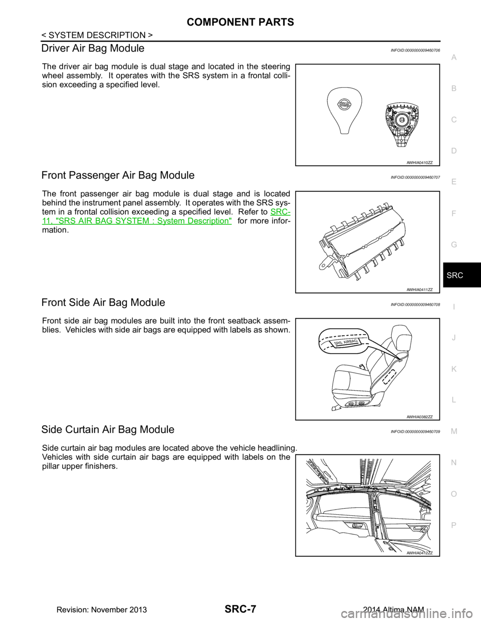
Driver Air Bag ModuleINFOID:0000000009460706
The driver air bag module is dual stage and located in the steering
wheel assembly. It operates with the SRS system in a frontal colli-
sion exceeding a specified level.
Front Passenger Air Bag ModuleINFOID:0000000009460707
The front passenger air bag module is dual stage and is located
behind the instrument panel assembly . It operates with the SRS sys-
tem in a frontal collision exceeding a specified level. Refer to SRC-
11, "SRS AIR BAG SYSTEM : System Description" for more infor-
mation.
Front Side Air Bag ModuleINFOID:0000000009460708
Front side air bag modules are built into the front seatback assem-
blies. Vehicles with side air bags are equipped with labels as shown.
Side Curtain Air Bag ModuleINFOID:0000000009460709
Side curtain air bag modules are located above the vehicle headlining.
Vehicles with side curtain air bags are equipped with labels on the
pillar upper finishers.
AWHIA0410ZZ
AWHIA0411ZZ
AWHIA0382ZZ
AWHIA0412ZZ
Revision: November 20132014 Altima NAMRevision: November 20132014 Altima NAM
Page 4104 of 4801

ST-1
STEERING
C
D E
F
H I
J
K L
M
SECTION ST
A
B
ST
N
O P
CONTENTS
STEERING SYSTEM
PRECAUTION ................ ...............................3
PRECAUTIONS .............................................. .....3
Precaution for Supplemental Restraint System
(SRS) "AIR BAG" and "SEAT BELT PRE-TEN-
SIONER" ............................................................. ......
3
Precaution for Steering System .......................... ......3
Precaution for Work ............................................ ......3
PREPARATION ............................................5
PREPARATION .............................................. .....5
Special Service Tool ........................................... ......5
Commercial Service Tool ..........................................5
SYSTEM DESCRIPTION ..............................7
COMPONENT PARTS ................................... .....7
HEATED STEERING WHEEL SYSTEM ............... ......7
HEATED STEERING WHEEL SYSTEM : Compo-
nent Parts Location ............................................. ......
7
HEATED STEERING WHEEL SYSTEM : Compo-
nent Description .................................................. ......
7
SYSTEM ..............................................................8
HEATED STEERING WHEEL SYSTEM ............... ......8
HEATED STEERING WHEEL SYSTEM : System
Diagram ............................................................... ......
8
HEATED STEERING WHEEL SYSTEM : System
Description .......................................................... ......
8
ECU DIAGNOSIS INFORMATION ...............9
A/C AUTO AMP. ............................................. .....9
List of ECU Reference ........................................ ......9
WIRING DIAGRAM ......................................10
HEATED STEERING WHEEL ........................ ....10
Wiring Diagram ................................................... ....10
BASIC INSPECTION ...................................13
DIAGNOSIS AND REPAIR WORK FLOW .......13
Work Flow ............................................................ ....13
POWER STEERING FLUID ..............................15
Inspection ................................................................15
STEERING WHEEL ..........................................16
Inspection ................................................................16
STEERING COLUMN ........................................18
Inspection ................................................................18
POWER STEERING OIL PUMP .......................19
Inspection ................................................................19
STEERING GEAR AND LINKAGE ...................20
Inspection ................................................................20
DTC/CIRCUIT DIAGNOSIS .........................21
POWER SUPPLY AND GROUND CIRCUIT ....21
A/C AUTO AMP. .................................................... ....21
A/C AUTO AMP. : Diagnosis Procedure .................21
HEATED STEERING WHEEL SYSTEM ...........22
Component Function Check ....................................22
Diagnosis Procedure ...............................................22
Component Inspection (Heated Steering Wheel
Switch) ................................................................. ....
24
Component Inspection (Heated Steering Relay) .....24
Component Inspection (Heated Steering Wheel) ....25
HEATED STEERING WHEEL SWITCH INDI-
CATOR LAMP ...................................................
26
Component Function Check ................................ ....26
Diagnosis Procedure ...............................................26
SYMPTOM DIAGNOSIS ..............................28
STEERING COLUMN ........................................28
Revision: November 20132014 Altima NAMRevision: November 20132014 Altima NAM
Page 4105 of 4801

ST-2
Symptom Table ......................................................28
NOISE, VIBRATION AND HARSHNESS
(NVH) TROUBLESHOOTING ......................... ...
29
NVH Troubleshooting Chart ................................ ...29
PERIODIC MAINTENANCE ..................... ...30
POWER STEERING FLUID ............................ ...30
Draining and Refilling .......................................... ...30
Air Bleeding Hydraulic System ...............................30
REMOVAL AND INSTAL LATION ...............31
STEERING WHEEL ........................................ ...31
Exploded View ..................................................... ...31
Removal and Installation ........................................31
STEERING COLUMN ........................................33
Exploded View ..................................................... ...33
Removal and Installation ........................................33
STEERING GEAR AND LINKAGE ....................36
Exploded View ..................................................... ...36
Removal and Installation ........................................36
POWER STEERING OIL PUMP ........................38
Exploded View ..................................................... ...38
Removal and Installation .........................................38
HYDRAULIC LINE .......................................... ...40
Exploded View ..................................................... ...40
Removal and Installation .........................................41
UNIT DISASSEMBLY AND ASSEMBLY ...43
STEERING GEAR AND LINKAGE ................ ...43
Exploded View ..................................................... ...43
Disassembly and Assembly ....................................43
POWER STEERING OIL PUMP ........................45
Disassembly and Assembly ................................. ...45
SERVICE DATA AND SPECIFICATIONS
(SDS) ............... ...........................................
46
SERVICE DATA AND SPECIFICATIONS
(SDS) .............................................................. ...
46
Steering Wheel .................................................... ...46
Steering Angle ........................................................46
Steering Column .....................................................46
Power Steering Gear ..............................................47
Power Steering Oil Pump ........................................48
Power Steering Fluid ...............................................48
Revision: November 20132014 Altima NAMRevision: November 20132014 Altima NAM
Page 4108 of 4801
PREPARATIONST-5
< PREPARATION >
C
D E
F
H I
J
K L
M A
B
ST
N
O P
PREPARATION
PREPARATION
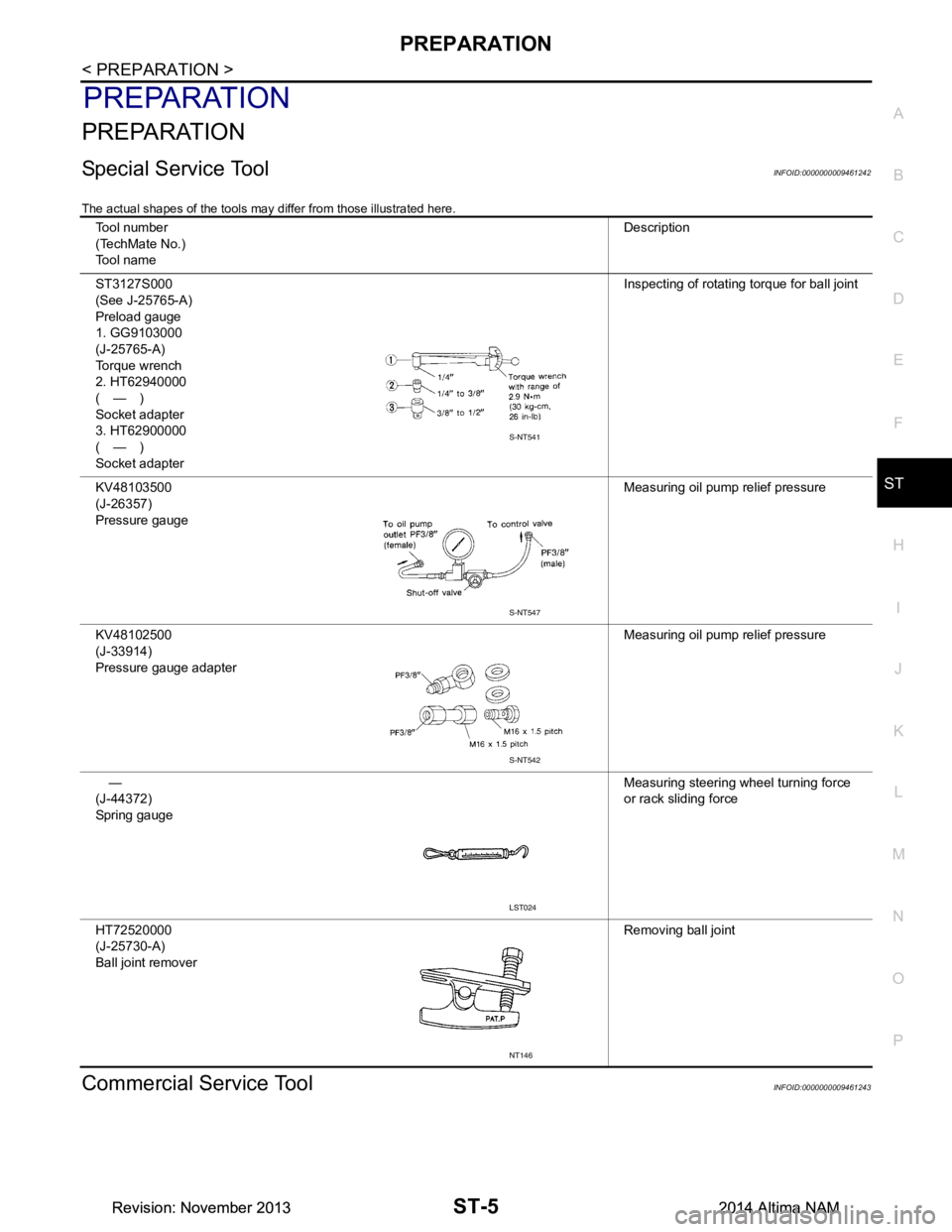
Special Service ToolINFOID:0000000009461242
The actual shapes of the tools may differ from those illustrated here.
Commercial Service ToolINFOID:0000000009461243
Tool number
(TechMate No.)
Tool name Description
ST3127S000
(See J-25765-A)
Preload gauge
1. GG9103000
(J-25765-A)
Torque wrench
2. HT62940000
(—)
Socket adapter
3. HT62900000
(—)
Socket adapter Inspecting of rotating torque for ball joint
KV48103500
(J-26357)
Pressure gauge Measuring oil pump relief pressure
KV48102500
(J-33914)
Pressure gauge adapter Measuring oil pump relief pressure
—
(J-44372)
Spring gauge Measuring steering wheel turning force
or rack sliding force
HT72520000
(J-25730-A)
Ball joint remover Removing ball joint
S-NT541
S-NT547
S-NT542
LST024
NT146
Revision: November 20132014 Altima NAMRevision: November 20132014 Altima NAM
Page 4109 of 4801
ST-6
< PREPARATION >
PREPARATION
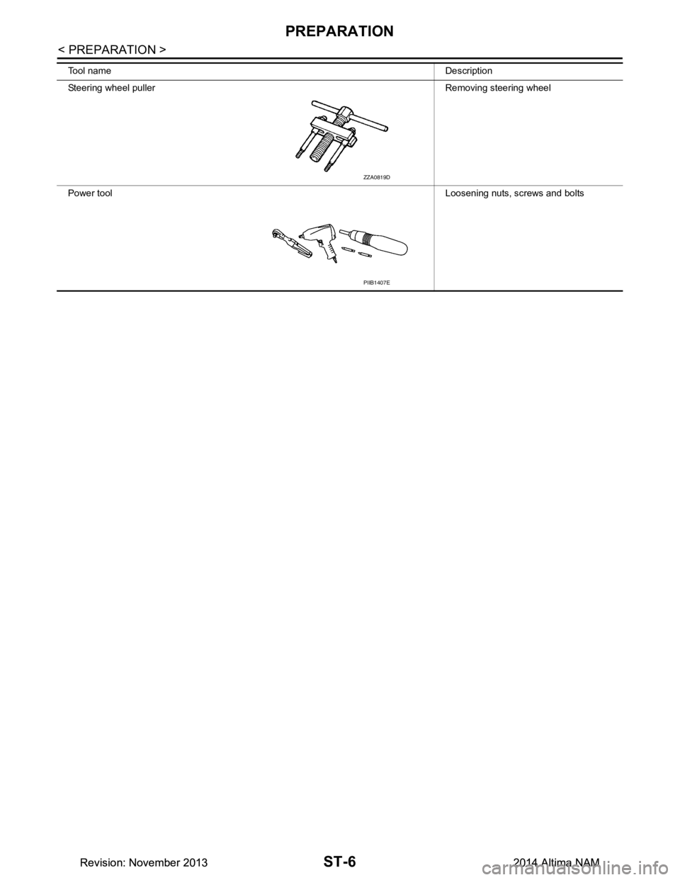
Tool nameDescription
Steering wheel puller Removing steering wheel
Power tool Loosening nuts, screws and bolts
ZZA0819D
PIIB1407E
Revision: November 20132014 Altima NAMRevision: November 20132014 Altima NAM
Page 4110 of 4801
COMPONENT PARTSST-7
< SYSTEM DESCRIPTION >
C
D E
F
H I
J
K L
M A
B
ST
N
O P
SYSTEM DESCRIPTION
COMPONENT PARTS
HEATED STEERING WHEEL SYSTEM
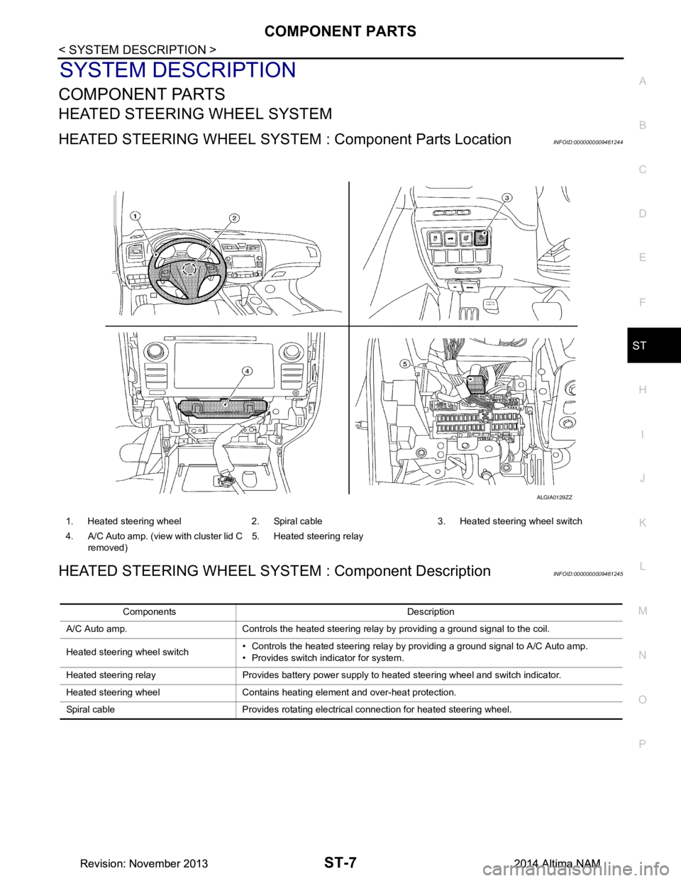
HEATED STEERING WHEEL SYSTEM : Component Parts LocationINFOID:0000000009461244
HEATED STEERING WHEEL SYSTEM : Component DescriptionINFOID:0000000009461245
1. Heated steering wheel 2. Spiral cable 3. Heated steering wheel switch
4. A/C Auto amp. (view with cluster lid C removed) 5. Heated steering relay
ALGIA0129ZZ
Components Description
A/C Auto amp. Controls the heated steering relay by providing a ground signal to the coil.
Heated steering wheel switch • Controls the heated steering relay by providing a ground signal to A/C Auto amp.
• Provides switch indicator for system.
Heated steering relay Provides battery power supply to heated steering wheel and switch indicator.
Heated steering wheel Contains heating element and over-heat protection.
Spiral cable Provides rotating electrical connection for heated steering wheel.
Revision: November 20132014 Altima NAMRevision: November 20132014 Altima NAM
Page 4111 of 4801
ST-8
< SYSTEM DESCRIPTION >
SYSTEM
SYSTEM
HEATED STEERING WHEEL SYSTEM
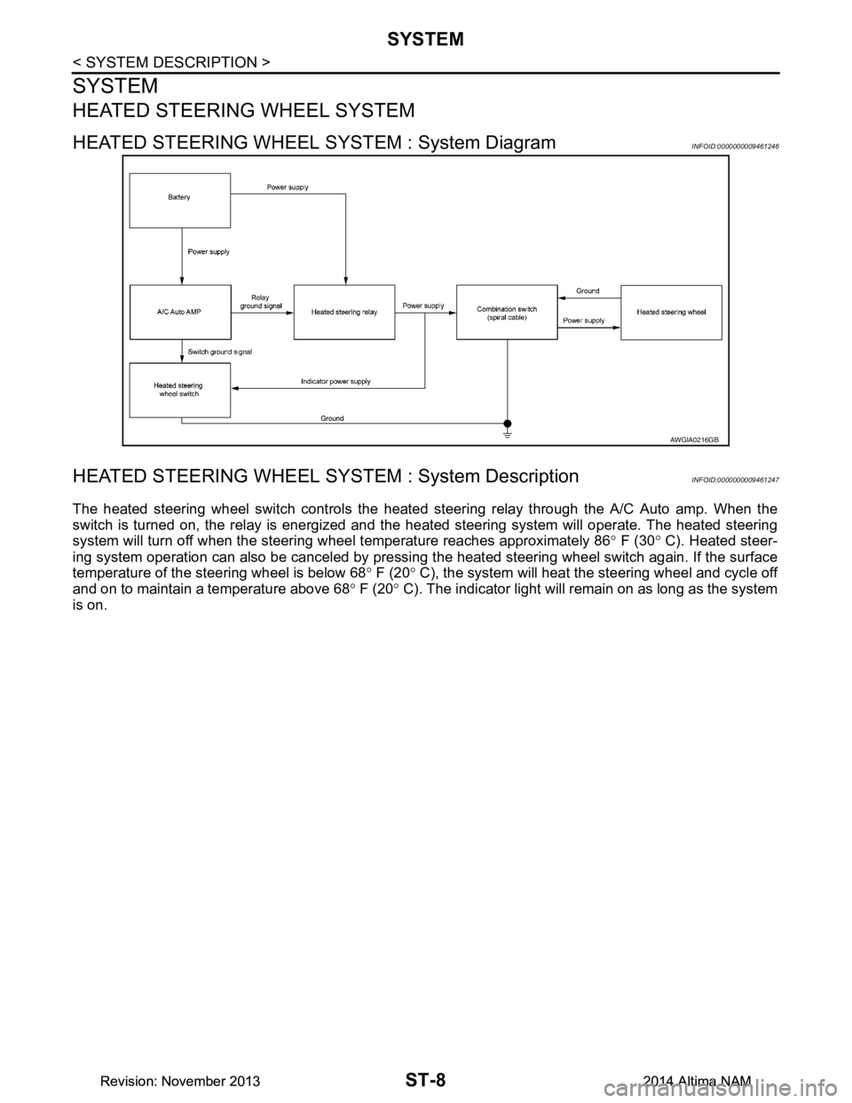
HEATED STEERING WHEEL SYSTEM : System DiagramINFOID:0000000009461246
HEATED STEERING WHEEL SYSTEM : System DescriptionINFOID:0000000009461247
The heated steering wheel switch c ontrols the heated steering relay through the A/C Auto amp. When the
switch is turned on, the relay is energized and t he heated steering system will operate. The heated steering
system will turn off when the steering w heel temperature reaches approximately 86 ° F (30 ° C). Heated steer-
ing system operation can also be canceled by pressing t he heated steering wheel switch again. If the surface
temperature of the steering wheel is below 68 ° F (20 ° C), the system will heat the steering wheel and cycle off
and on to maintain a temperature above 68 ° F (20 ° C). The indicator light will remain on as long as the system
is on.
AWGIA0216GB
Revision: November 20132014 Altima NAMRevision: November 20132014 Altima NAM