2014 NISSAN TEANA sensor
[x] Cancel search: sensorPage 887 of 4801

UNLOCK SENSORDLK-119
< DTC/CIRCUIT DIAGNOSIS >
C
D E
F
G H
I
J
L
M A
B
DLK
N
O P
UNLOCK SENSOR
DescriptionINFOID:0000000009461849
Detects door lock condition of driver door.
Component Function CheckINFOID:0000000009461850
1.CHECK FUNCTION
With CONSULT
Check unlock sensor UNLK SEN –DR in “Data Monitor” mode.
Is the inspection result normal?
YES >> Unlock sensor is OK.
NO >> Refer to DLK-119, "Diagnosis Procedure"
.
Diagnosis ProcedureINFOID:0000000009461851
Regarding Wiring Diagram information, refer to DLK-51, "Wiring Diagram".
1.CHECK UNLOCK SENSOR POWER SUPPLY
Check signal between BCM connector and ground with oscilloscope.
Is the inspection result normal?
YES >> GO TO 6
NO >> GO TO 2
2.CHECK UNLOCK SENSOR CIRCUIT
1. Turn ignition switch OFF.
2. Disconnect BCM and front door lock assembly LH connector.
3. Check continuity between BCM connector and front door lock assembly LH connector.
4. Check continuity between BCM connector and ground.
Monitor item Condition
UNLK SEN –DR Front door lock (driver side) LOCK : ON
Front door lock (dri ver side) UNLOCK : OFF
Te r m i n a l s
Front door lock assembly
LH condition Voltage (V)
(Approx.)
(+)
(–)
BCM connector Terminal
M17 30 Ground Locked
Unlocked 0
JPMIA0011GB
BCM connector Terminal Front door lock assem-
bly LH connector Terminal Continuity
M17 30 D14 3 Yes
Revision: November 20132014 Altima NAMRevision: November 20132014 Altima NAM
Page 888 of 4801

DLK-120
< DTC/CIRCUIT DIAGNOSIS >
UNLOCK SENSOR
Is the inspection result normal?
YES >> GO TO 3
NO >> Repair or replace harness between BCM and front door lock assembly LH.
3.CHECK UNLOCK SENSOR GROUND CIRCUIT
Check continuity between front door lock assembly LH connector and ground.
Is the inspection result normal?
YES >> GO TO 4
NO >> Repair or replace harness.
4.CHECK BCM OUTPUT SIGNAL
1. Connect BCM harness connector.
2. Check signal between BCM connector and ground with oscilloscope.
Is the inspection result normal?
YES >> GO TO 5
NO >> Replace BCM. Refer to BCS-80, "Removal and Installation"
5.CHECK UNLOCK SENSOR
Refer to DLK-120, "Component Inspection"
.
Is the inspection result normal?
YES >> GO TO 6
NO >> Replace front door lock assembly LH. Refer to DLK-203, "FRONT DOOR LOCK : Removal and
Installation".
6.CHECK INTERMITTENT INCIDENT
Refer to GI-43, "Intermittent Incident"
.
>> Inspection End.
Component InspectionINFOID:0000000009461852
1.CHECK UNLOCK SENSOR
Check unlock sensor.
BCM connector Terminal GroundContinuity
M17 30 No
Front door lock assembly LH connector Te r m i n a l
GroundContinuity
D14 4 Yes
Te r m i n a l s Voltage (V)
(Approx.)
(+)
(–)
BCM connector Terminal
M17 30 Ground
JPMIA0011GB
Revision: November 20132014 Altima NAMRevision: November 20132014 Altima NAM
Page 889 of 4801

UNLOCK SENSORDLK-121
< DTC/CIRCUIT DIAGNOSIS >
C
D E
F
G H
I
J
L
M A
B
DLK
N
O P
Is the inspection result normal?
YES >> Inspection End.
NO >> Replace front lock assembly LH. Refer to DLK-203, "FRONT DOOR LOCK : Removal and Instal-
lation".
Te r m i n a l
Front door lock assembly LH
condition Continuity
Front door lock assembly LH
34 Unlock Yes
Lock No
Revision: November 20132014 Altima NAMRevision: November 20132014 Altima NAM
Page 928 of 4801

DLK-160
< SYMPTOM DIAGNOSIS >
KEY REMINDER FUNCTION SYMPTOMS
KEY REMINDER FUNCTION SYMPTOMS
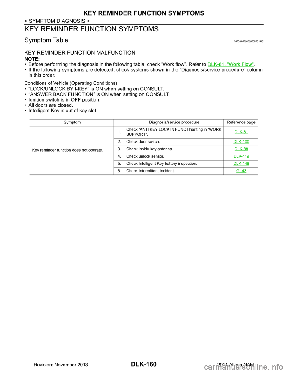
Symptom TableINFOID:0000000009461915
KEY REMINDER FUNCTION MALFUNCTION
NOTE:
• Before performing the diagnosis in the follo wing table, check “Work flow”. Refer to DLK-81, "Work Flow"
.
• If the following symptoms are detected, check syst ems shown in the “Diagnosis/service procedure” column
in this order.
Conditions of Vehicle (Operating Conditions)
• “LOCK/UNLOCK BY I-KEY” is ON when setting on CONSULT.
• “ANSWER BACK FUNCTION” is ON when setting on CONSULT.
• Ignition switch is in OFF position.
• All doors are closed.
• Intelligent Key is out of key slot.
Symptom Diagnosis/service procedure Reference page
Key reminder function does not operate. 1.
Check “ANTI KEY LOCK IN FUNCTI”setting in “WORK
SUPPORT”. DLK-81
2. Check door switch.
DLK-100
3. Check inside key antenna. DLK-88
4. Check unlock sensor.DLK-119
5. Check Intelligent Key battery inspection.DLK-146
6. Check Intermittent Incident. GI-43
Revision: November 20132014 Altima NAMRevision: November 20132014 Altima NAM
Page 947 of 4801

RADIATOR CORE SUPPORTDLK-179
< REMOVAL AND INSTALLATION >
C
D E
F
G H
I
J
L
M A
B
DLK
N
O P
RADIATOR CORE SUPPORT
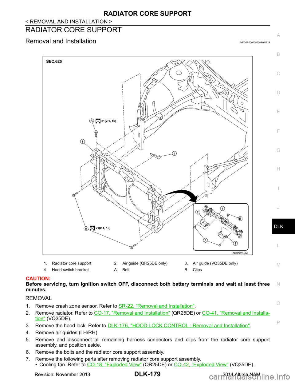
Removal and InstallationINFOID:0000000009461929
CAUTION:
Before servicing, turn igni tion switch OFF, disconnect both batt ery terminals and wait at least three
minutes.
REMOVAL
1. Remove crash zone sensor. Refer to SR-22, "Removal and Installation".
2. Remove radiator. Refer to CO-17, "Removal and Installation"
(QR25DE) or CO-41, "Removal and Installa-
tion" (VQ35DE).
3. Remove the hood lock. Refer to DLK-176, "HOOD LOCK CONTROL : Removal and Installation"
.
4. Remove air guides (LH/RH).
5. Remove and disconnect all remaining harness connectors and clips from the radiator core support assembly, and position aside.
6. Remove the bolts and the radiator core support assembly.
7. Remove the following parts after removing radiator core support assembly. • Cooling fan. Refer to CO-18, "Exploded View"
(QR25DE) or CO-42, "Exploded View" (VQ35DE).
1. Radiator core support 2. Air guide (QR25DE only) 3. Air guide (VQ35DE only)
4. Hood switch bracket A. Bolt B. Clips
ALKIA2744ZZ
Revision: November 20132014 Altima NAMRevision: November 20132014 Altima NAM
Page 952 of 4801

DLK-184
< REMOVAL AND INSTALLATION >
FRONT DOOR
FRONT DOOR
DOOR ASSEMBLY
DOOR ASSEMBLY : Removal and InstallationINFOID:0000000009461933
CAUTION:
• Use two people when removing or installing the front door assembly due to its heavy weight.
• When removing and installing front door assembl y, support front door with a suitable tool.
• Do not use air tools or el ectric tools for servicing.
• Before servicing, turn ignition sw itch OFF, disconnect both battery terminals and wait at least three
minutes.
NOTE:
LH side shown; RH side similar.
REMOVAL
1. Disconnect the battery negative and positive terminals and wait at least three minutes with the side air bag (satellite) sensor (if equipped).
2. Remove front door harness grommet LH (1) then pull out door harness from body (2).
3. Disconnect the harness connectors (A) from the front door har- ness.
4. Remove the check link bolt (body side).
JMKIA8070ZZ
JMKIA8071ZZ
Revision: November 20132014 Altima NAMRevision: November 20132014 Altima NAM
Page 1001 of 4801

EC-1
ENGINE
C
D E
F
G H
I
J
K L
M
SECTION EC
A
EC
N
O P
CONTENTS
ENGINE CONTROL SYSTEM
QR25DE
PRECAUTION ................ ..............................
15
PRECAUTIONS .............................................. ....15
Precaution for Supplemental Restraint System
(SRS) "AIR BAG" and "SEAT BELT PRE-TEN-
SIONER" ............................................................. ....
15
Precaution for Procedure without Cowl Top Cover ....15
On Board Diagnostic (OBD) System of Engine
and CVT .............................................................. ....
15
General Precautions ...............................................16
PREPARATION ...........................................19
PREPARATION .............................................. ....19
Special Service Tools .......................................... ....19
Commercial Service Tools ......................................19
SYSTEM DESCRIPTION .............................21
COMPONENT PARTS ................................... ....21
Component Parts Location ................................ ....21
ECM ........................................................................25
Accelerator Pedal Position Sensor ...................... ....25
Electric Throttle Control Actuator ........................ ....25
Ignition Coil With Power Transistor .........................26
Fuel Injector ........................................................ ....26
Fuel Level Sensor Unit and Fuel Pump .............. ....26
Fuel Tank Temperature Sensor .......................... ....27
Mass Air Flow Sensor (With Intake Air Tempera-
ture Sensor) ........................................................ ....
27
Manifold Absolute Pressure Sensor ........................28
Engine Coolant Temperature Sensor .................. ....28
Crankshaft Position Sensor (POS) ..........................29
Camshaft Position Sens or (PHASE) .......................29
Intake Valve Timing Cont rol Solenoid Valve ...........30
Intake Valve Timing Intermediate Lock Control
Solenoid Valve .................................................... ....
30
Exhaust Valve Timing Control Position Sensor .......30
Exhaust Valve Timing Control Solenoid Valve ........31
Intake Manifold Runner Control Valve ................. ....31
Intake Manifold Tuning Valve ..................................31
Air Fuel Ratio (A/F) Sensor 1 ..................................32
Heated Oxygen Sensor 2 ........................................32
Knock Sensor ..........................................................33
Engine Oil Pressure Sensor ....................................33
Engine Oil Temperature Sensor .......................... ....33
Cooling Fan .............................................................34
EVAP Canister .........................................................34
EVAP Canister Purge Volu me Control Solenoid
Valve .................................................................... ....
34
EVAP Canister Vent Control Valve ..........................35
EVAP Control System Pres sure Sensor ..................35
Battery Current Sensor (With Battery Tempera-
ture Sensor) ......................................................... ....
35
Malfunction Indicator lamp (MIL) .............................36
Oil Pressure Warning Lamp ....................................36
Refrigerant Pressure Sensor ............................... ....36
Stop Lamp Switch & Brake Pedal Position Switch ....36
ASCD Steering Switch .............................................37
Information Display ..................................................37
STRUCTURE AND OPERATION .....................38
Positive Crankcase Ventilation ................................38
On Board Refueling Vapor Recovery (ORVR) ........39
SYSTEM ............................................................40
ENGINE CONTROL SYSTEM ........................ ...........40
ENGINE CONTROL SYSTEM : System Descrip-
tion ....................................................................... ....
40
ENGINE CONTROL SYSTEM : Fail Safe ..............41
MULTIPORT FUEL INJECTION SYSTEM ................43
MULTIPORT FUEL INJECTION SYSTEM : Sys-
tem Description (with auto matic air conditioner) ......
43
MULTIPORT FUEL INJECTION SYSTEM : Sys-
tem Description (with manual air conditioner) .........
46
ELECTRIC IGNITION SYSTEM .................................48
ELECTRIC IGNITION SYSTEM : System De-
scription ............................................................... ....
48
Revision: November 20132014 Altima NAMRevision: November 20132014 Altima NAM
Page 1003 of 4801

EC-3
C
D E
F
G H
I
J
K L
M
EC A
N
O P
Description ..........................................................
..
181
Work Procedure ....................................................181
FUEL PRESSURE .......................................... ..182
Work Procedure .................................................. ..182
HOW TO SET SRT CODE ................................183
Description .......................................................... ..183
SRT Set Driving Pattern ........................................184
Work Procedure ....................................................186
HOW TO ERASE PERMANENT DTC ..............189
Description .......................................................... ..189
Work Procedure (Group A) ...................................190
Work Procedure (Group B) ...................................192
DTC/CIRCUIT DIAGNOSIS .......................195
TROUBLE DIAGNOSIS - SPECIFICATION
VALUE ............................................................ ..
195
Description .......................................................... ..195
Component Function Check ..................................195
Diagnosis Procedure .............................................196
POWER SUPPLY AND GROUND CIRCUIT ....203
Diagnosis Procedure ........................................... ..203
U0101 CAN COMM CIRCUIT ...........................207
Description .......................................................... ..207
DTC Logic .............................................................207
Diagnosis Procedure .............................................207
U1001 CAN COMM CIRCUIT ...........................208
Description .......................................................... ..208
DTC Logic .............................................................208
Diagnosis Procedure .............................................208
P0011 IVT CONTROL ......................................209
DTC Logic ........................................................... ..209
Diagnosis Procedure .............................................210
Component Inspection ..........................................211
P0014 EVT CONTROL .....................................212
DTC Logic ........................................................... ..212
Diagnosis Procedure .............................................213
Component Inspection ..........................................214
P0031, P0032 A/F SENSOR 1 HEATER .........215
DTC Logic ........................................................... ..215
Diagnosis Procedure .............................................215
Component Inspection ..........................................216
P0037, P0038 HO2S2 HEATER .......................218
DTC Logic ........................................................... ..218
Diagnosis Procedure .............................................218
Component Inspection ..........................................219
P0075 INTAKE VALVE TIMING CONTROL ....221
DTC Logic ........................................................... ..221
Diagnosis Procedure .............................................221
Component Inspection (IVT Control Solenoid
Valve) .................................................................. ..
223
Component Inspection (IVT Intermediate Lock
Control Solenoid Valve) ....................................... ..
224
P0078 EVT CONTROL SOLENOID VALVE ...225
DTC Logic ..............................................................225
Diagnosis Procedure .............................................225
Component Inspection ...........................................226
P0101 MAF SENSOR .....................................228
DTC Logic ..............................................................228
Diagnosis Procedure .............................................228
Component Inspection ...........................................230
P0102, P0103 MAF SENSOR .........................232
DTC Logic ..............................................................232
Diagnosis Procedure .............................................232
Component Inspection ...........................................234
P010A MANIFOLD ABSOLUTE PRESSURE
SENSOR ..........................................................
236
DTC Logic ............................................................ ..236
Diagnosis Procedure .............................................236
Component Inspection (MAP Sensor) ...................237
P0111 IAT SENSOR .......................................239
DTC Logic ..............................................................239
Component Function Check ..................................240
Diagnosis Procedure .............................................240
Component Inspection ...........................................240
P0112, P0113 IAT SENSOR ...........................241
DTC Logic ..............................................................241
Diagnosis Procedure .............................................241
Component Inspection ...........................................242
P0116 ECT SENSOR ......................................243
DTC Logic ..............................................................243
Component Function Check ..................................244
Diagnosis Procedure .............................................244
Component Inspection ...........................................244
P0117, P0118 ECT SENSOR ..........................245
DTC Logic ..............................................................245
Diagnosis Procedure .............................................245
Component Inspection ...........................................246
P0122, P0123 TP SENSOR ............................248
DTC Logic ..............................................................248
Diagnosis Procedure .............................................248
Component Inspection ...........................................250
P0125 ECT SENSOR ......................................251
DTC Logic ..............................................................251
Diagnosis Procedure .............................................251
Component Inspection ...........................................252
P0127 IAT SENSOR .......................................253
DTC Logic ..............................................................253
Diagnosis Procedure .............................................253
Component Inspection ...........................................254
P0128 THERMOSTAT FUNCTION .................255
Revision: November 20132014 Altima NAMRevision: November 20132014 Altima NAM