Page 2441 of 4801
FENDER PROTECTOREXT-27
< REMOVAL AND INSTALLATION >
C
D E
F
G H
I
J
L
M A
B
EXT
N
O P
REAR WHEEL HOUSE PROTECTOR : Exploded ViewINFOID:0000000009461004
REAR WHEEL HOUSE PROTECTOR : Removal and InstallationINFOID:0000000009461005
REMOVAL
1. Remove the rear tires. Refer to WT-55, "Adjustment".
2. Remove the rear wheel house protector clips.
3. Remove rear wheel house protector plastic nuts and the rear wheel house protector.
INSTALLATION
Installation is in the reverse order of removal.
1. Rear wheel house protector A. Plastic nut B. Clip
ALKIA2667ZZ
Revision: November 20132014 Altima NAM
Page 2444 of 4801
EXT-30
< REMOVAL AND INSTALLATION >
MUDGUARD
MUDGUARD
Exploded ViewINFOID:0000000009461009
NOTE:
LH side shown; RH side similar.
Removal and InstallationINFOID:0000000009461010
REMOVAL
1. Remove the center mudguard clips located on the under body.
2. Remove the center mudguard screws and the center mudguard.
INSTALLATION
Installation is in the reverse order of removal.
1. Center mudguard 2. Rear wheel wind deflector Clips
Front
ALKIA2661ZZ
Revision: November 20132014 Altima NAM
Page 2453 of 4801

FAX-1
TRANSMISSION & DRIVELINE
CEF
G H
I
J
K L
M
SECTION FA X
A
B
FA X
N
O P
CONTENTS
FRONT AXLE
PRECAUTION ................ ...............................2
PRECAUTIONS .............................................. .....2
Precaution for Supplemental Restraint System
(SRS) "AIR BAG" and "SEAT BELT PRE-TEN-
SIONER" ............................................................. ......
2
Precautions for Drive Shaft .......................................2
PREPARATION ............................................3
PREPARATION .............................................. .....3
Special Service Tool ........................................... ......3
Commercial Service Tool ..........................................3
SYMPTOM DIAGNOSIS ...............................5
NOISE, VIBRATION, AND HARSHNESS
(NVH) TROUBLESHOOTING ........................ .....
5
NVH Troubleshooting Chart ................................ ......5
PERIODIC MAINTENANCE ..........................6
FRONT WHEEL HUB ..................................... .....6
Inspection ............................................................ ......6
FRONT DRIVE SHAFT ........................................7
Inspection ............................................................ ......7
REMOVAL AND INSTALLATION ................8
FRONT WHEEL HUB .........................................8
Exploded View ..................................................... .....8
Removal and Installation ..........................................8
FRONT DRIVE SHAFT .....................................10
Exploded View (LH) .................................................10
Removal and Installation (LH) .................................10
Exploded View (RH) ............................................ ....12
Removal and Installation (RH) .................................12
UNIT DISASSEMBLY AND ASSEMBLY ....15
FRONT DRIVE SHAFT .....................................15
Disassembly and Assembly (LH) ......................... ....15
Disassembly and Assembly (RH) ............................20
SERVICE DATA AND SPECIFICATIONS
(SDS) ............... .............................................
27
SERVICE DATA AND SPECIFICATIONS
(SDS) .................................................................
27
Wheel Bearing ..................................................... ....27
Drive Shaft ...............................................................27
Dynamic Damper .....................................................27
Boot Bands ..............................................................28
Revision: November 20132014 Altima NAM
Page 2457 of 4801

NOISE, VIBRATION, AND HARSHNESS (NVH) TROUBLESHOOTINGFAX-5
< SYMPTOM DIAGNOSIS >
CEF
G H
I
J
K L
M A
B
FA X
N
O P
SYMPTOM DIAGNOSIS
NOISE, VIBRATION, AND HARSHNESS (N VH) TROUBLESHOOTING
NVH Troubleshooting ChartINFOID:0000000009464433
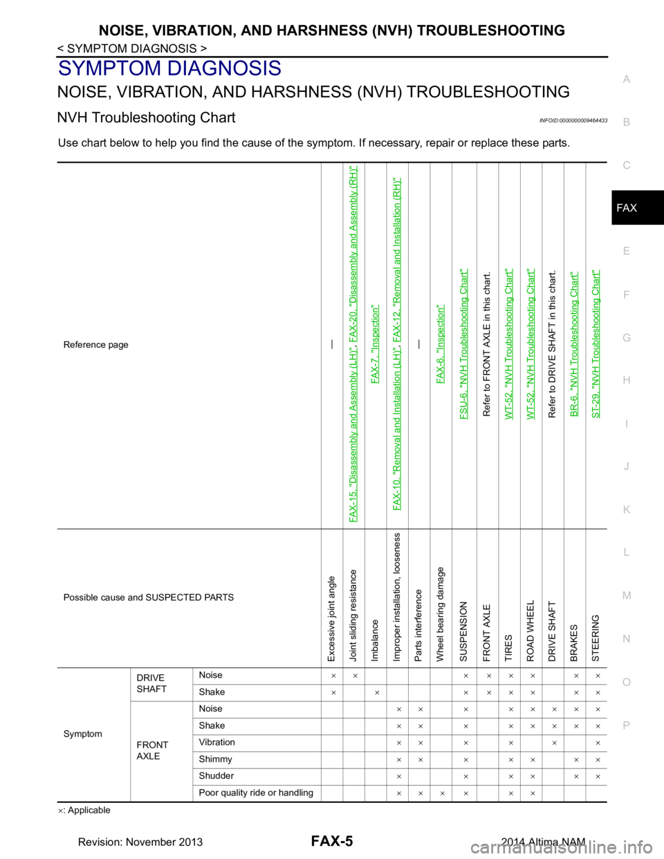
Use chart below to help you find the cause of the symptom. If necessary, repair or replace these parts.
×: ApplicableReference page
—
FAX-15, "Disassembly and Assembly (LH)", FAX-20, "Disassembly and Assembly (RH)"
FAX-7, "Inspection"
FAX-10, "Removal and Installation (LH)"
, FAX-12, "Removal and Installation (RH)"—
FAX-6, "Inspection"
FSU-6, "NVH Troubleshooting Chart"Refer to FRONT AXLE in this chart.
WT-52, "NVH Troubleshooting Chart"WT-52, "NVH Troubleshooting Chart"Refer to DRIVE SHAFT in this chart. BR-6, "NVH Troubleshooting Chart"ST-29, "NVH Troubleshooting Chart"
Possible cause and SUSPECTED PARTS
Excessive joint angle
Joint sliding resistance
Imbalance
Improper installation, looseness
Parts interference
Wheel bearing damage
SUSPENSION
FRONT AXLE
TIRES
ROAD WHEEL
DRIVE SHAFT
BRAKES
STEERING
Symptom DRIVE
SHAFT Noise
×× × ××× ××
Shake × × × ××× ××
FRONT
AXLE Noise
×× × ×××××
Shake ×× × ×××××
Vibration ××××××
Shimmy ×××××××
Shudder ××××××
Poor quality ride or handling ××× × ××
Revision: November 20132014 Altima NAM
Page 2458 of 4801
FAX-6
< PERIODIC MAINTENANCE >
FRONT WHEEL HUB
PERIODIC MAINTENANCE
FRONT WHEEL HUB
InspectionINFOID:0000000009464436
• Move wheel hub and bearing assembly in the axial direction by hand. Make sure there is no looseness of
wheel bearing.
• Rotate wheel hub and make sure that is no unusual noise or other irregular conditions. If there is any of irregular conditions, replace wheel hub and bearing assembly Axial end play : Refer to
FAX-27, "Wheel Bearing"
.
Revision: November 20132014 Altima NAM
Page 2460 of 4801
FAX-8
< REMOVAL AND INSTALLATION >
FRONT WHEEL HUB
REMOVAL AND INSTALLATION
FRONT WHEEL HUB
Exploded ViewINFOID:0000000009464438
Removal and InstallationINFOID:0000000009464439
REMOVAL
1. Remove front wheel and tire using power tool. Refer to WT-55, "Adjustment".
2. Remove brake caliper using power tool, leaving brak e caliper hydraulic hose attached. Position brake cal-
iper aside with wire. Refer to BR-36, "BRAKE CALIPER ASSEMBLY : Exploded View"
.
CAUTION:
• Do not depress brake pedal while brake caliper is removed.
• Do not twist or stretch the brake hose.
3. Put alignment marks on disc rotor and wheel hub and bearing assembly, then remove disc rotor.
1. Cotter pin 2. Nut retainer 3. Rotor
4. Wheel hub and bearing assembly 5. Wheel hub bolt 6. Splash guard
7. Steering knuckle Front
AWEIA0264ZZ
SDIA1480E
Revision: November 20132014 Altima NAM
Page 2461 of 4801

FRONT WHEEL HUBFAX-9
< REMOVAL AND INSTALLATION >
CEF
G H
I
J
K L
M A
B
FA X
N
O P
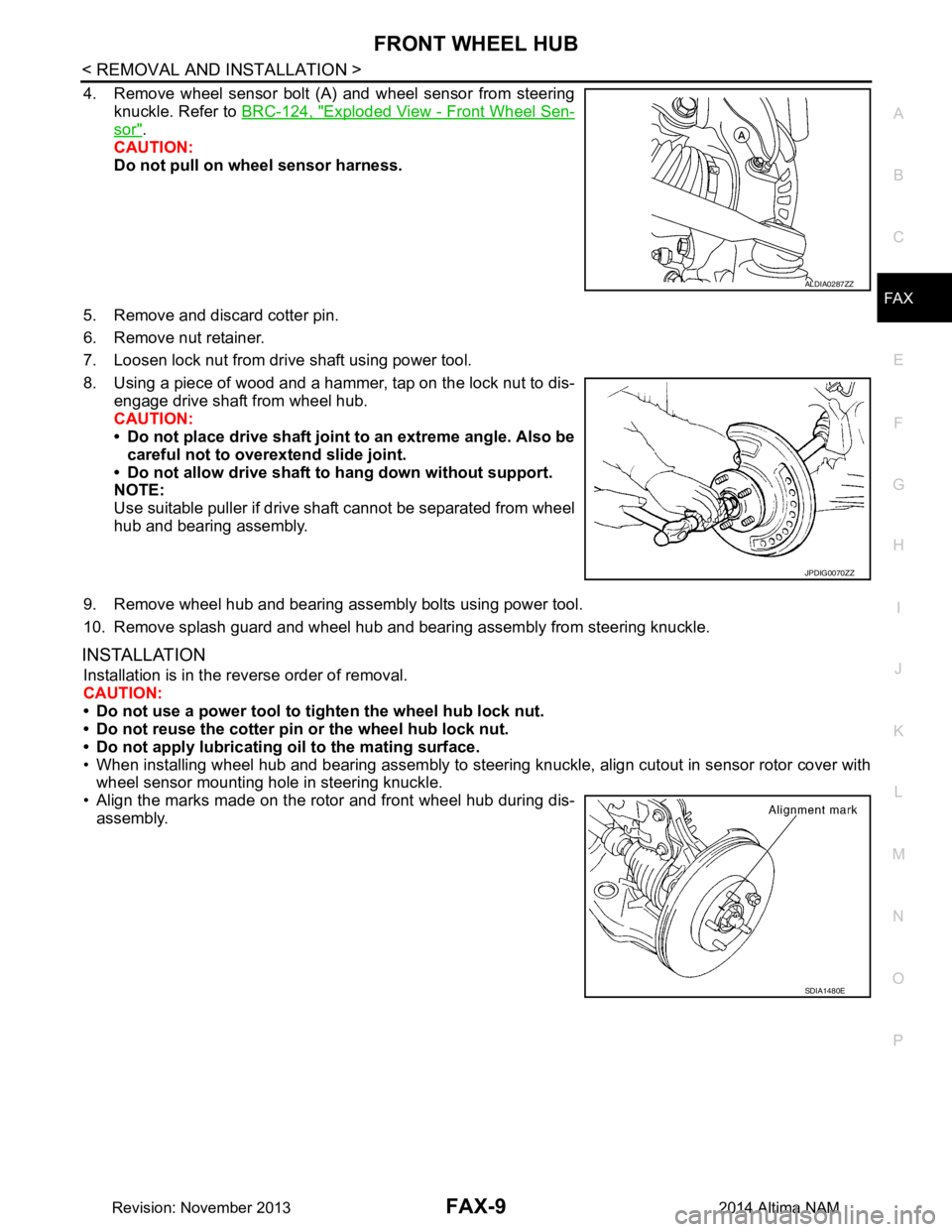
4. Remove wheel sensor bolt (A) and wheel sensor from steering knuckle. Refer to BRC-124, "Exploded View - Front Wheel Sen-
sor".
CAUTION:
Do not pull on wheel sensor harness.
5. Remove and discard cotter pin.
6. Remove nut retainer.
7. Loosen lock nut from drive shaft using power tool.
8. Using a piece of wood and a hammer, tap on the lock nut to dis- engage drive shaft from wheel hub.
CAUTION:
• Do not place drive shaft joint to an extreme angle. Also be careful not to over extend slide joint.
• Do not allow drive shaft to hang down without support.
NOTE:
Use suitable puller if drive shaft cannot be separated from wheel
hub and bearing assembly.
9. Remove wheel hub and bearing assembly bolts using power tool.
10. Remove splash guard and wheel hub and bearing assembly from steering knuckle.
INSTALLATION
Installation is in the reverse order of removal.
CAUTION:
• Do not use a power tool to tighten the wheel hub lock nut.
• Do not reuse the cotter pin or the wheel hub lock nut.
• Do not apply lubricating oil to the mating surface.
• When installing wheel hub and bearing assembly to steering knuckle, align cutout in sensor rotor cover with wheel sensor mounting hole in steering knuckle.
• Align the marks made on the rotor and front wheel hub during dis- assembly.
ALDIA0287ZZ
JPDIG0070ZZ
SDIA1480E
Revision: November 20132014 Altima NAM
Page 2462 of 4801

FAX-10
< REMOVAL AND INSTALLATION >
FRONT DRIVE SHAFT
FRONT DRIVE SHAFT
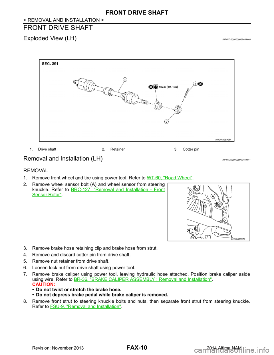
Exploded View (LH)INFOID:0000000009464440
Removal and Installation (LH)INFOID:0000000009464441
REMOVAL
1. Remove front wheel and tire using power tool. Refer to WT-60, "Road Wheel".
2. Remove wheel sensor bolt (A) and wheel sensor from steering knuckle. Refer to BRC-127, "Removal and Installation - Front
Sensor Rotor".
3. Remove brake hose retaining clip and brake hose from strut.
4. Remove and discard cotter pin from drive shaft.
5. Remove nut retainer from drive shaft.
6. Loosen lock nut from drive shaft using power tool.
7. Remove brake caliper using power tool, leaving hy draulic hose attached. Position brake caliper aside
using wire. Refer to BR-36, "BRAKE CALIPER ASSEMBLY : Removal and Installation"
.
CAUTION:
• Do not twist or stretch the brake hose.
• Do not depress brake pedal while brake caliper is removed.
8. Remove front strut to steering knuckle bolts and nut s, then separate front strut from steering knuckle.
Refer to FSU-9, "Removal and Installation"
.
1. Drive shaft 2. Retainer 3. Cotter pin
AWDIA0983GB
ALDIA0287ZZ
Revision: November 20132014 Altima NAM