Page 4126 of 4801
HEATED STEERING WHEEL SYSTEMST-23
< DTC/CIRCUIT DIAGNOSIS >
C
D E
F
H I
J
K L
M A
B
ST
N
O P
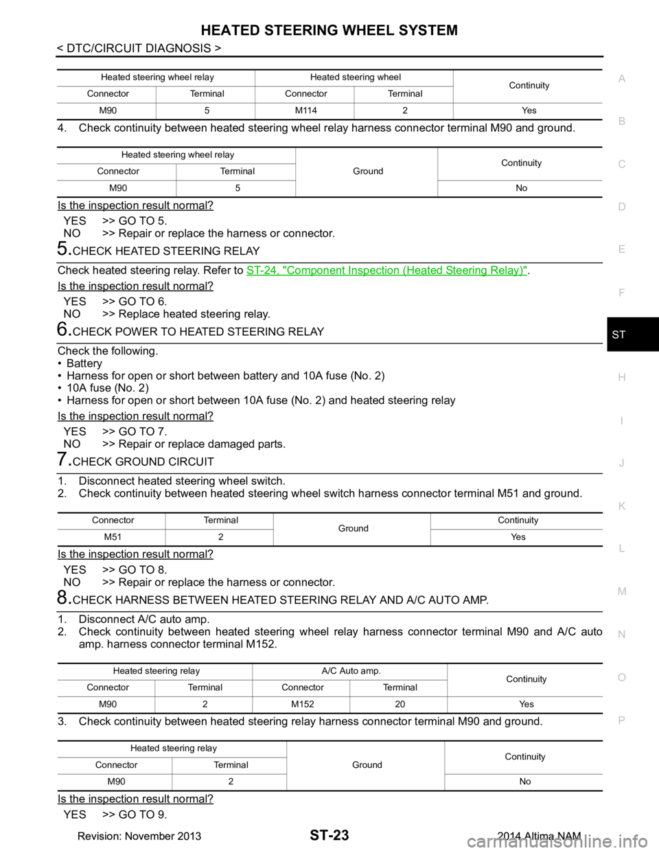
4. Check continuity between heated steering wheel relay harness connector terminal M90 and ground.
Is the inspection result normal?
YES >> GO TO 5.
NO >> Repair or replace the harness or connector.
5.CHECK HEATED STEERING RELAY
Check heated steering relay. Refer to ST-24, "Component Inspection (Heated Steering Relay)"
.
Is the inspection result normal?
YES >> GO TO 6.
NO >> Replace heated steering relay.
6.CHECK POWER TO HEATED STEERING RELAY
Check the following.
•Battery
• Harness for open or short between battery and 10A fuse (No. 2)
• 10A fuse (No. 2)
• Harness for open or short between 10A fuse (No. 2) and heated steering relay
Is the inspection result normal?
YES >> GO TO 7.
NO >> Repair or replace damaged parts.
7.CHECK GROUND CIRCUIT
1. Disconnect heated steering wheel switch.
2. Check continuity between heated steering wheel switch harness connector terminal M51 and ground.
Is the inspection result normal?
YES >> GO TO 8.
NO >> Repair or replace the harness or connector.
8.CHECK HARNESS BETWEEN HEATED STEE RING RELAY AND A/C AUTO AMP.
1. Disconnect A/C auto amp.
2. Check continuity between heated steering wheel relay harness connector terminal M90 and A/C auto
amp. harness connector terminal M152.
3. Check continuity between heated steering re lay harness connector terminal M90 and ground.
Is the inspection result normal?
YES >> GO TO 9.
Heated steering wheel relay Heated steering wheel Continuity
Connector Terminal Connector Terminal
M90 5 M114 2 Yes
Heated steering wheel relay GroundContinuity
Connector Terminal
M90 5 No
Connector Terminal GroundContinuity
M51 2 Yes
Heated steering relay A/C Auto amp. Continuity
Connector Terminal Connector Terminal
M90 2 M152 20 Yes
Heated steering relay GroundContinuity
Connector Terminal
M90 2 No
Revision: November 20132014 Altima NAMRevision: November 20132014 Altima NAM
Page 4129 of 4801
ST-26
< DTC/CIRCUIT DIAGNOSIS >
HEATED STEERING WHEEL SWITCH INDICATOR LAMP
HEATED STEERING WHEEL SWITCH INDICATOR LAMP
Component Function CheckINFOID:0000000009461262
1.CHECK HEATED STEERING WHEEL SWITCH INDICATOR LAMP
1. Turn ignition switch ON.
2. Turn heated steering wheel switch ON. Observe indicator.
3. Turn heated steering wheel switch OFF. Observe indicator.
Does heated steering wheel switch indicator lamp turn ON and then OFF?
YES >> Inspection End.
NO >> Go to ST-26, "Diagnosis Procedure"
.
Diagnosis ProcedureINFOID:0000000009461263
1.CHECK POWER CIRCUIT
1. Turn ignition switch OFF.
2. Remove the heated steering wheel switch.
3. Turn ignition switch ON.
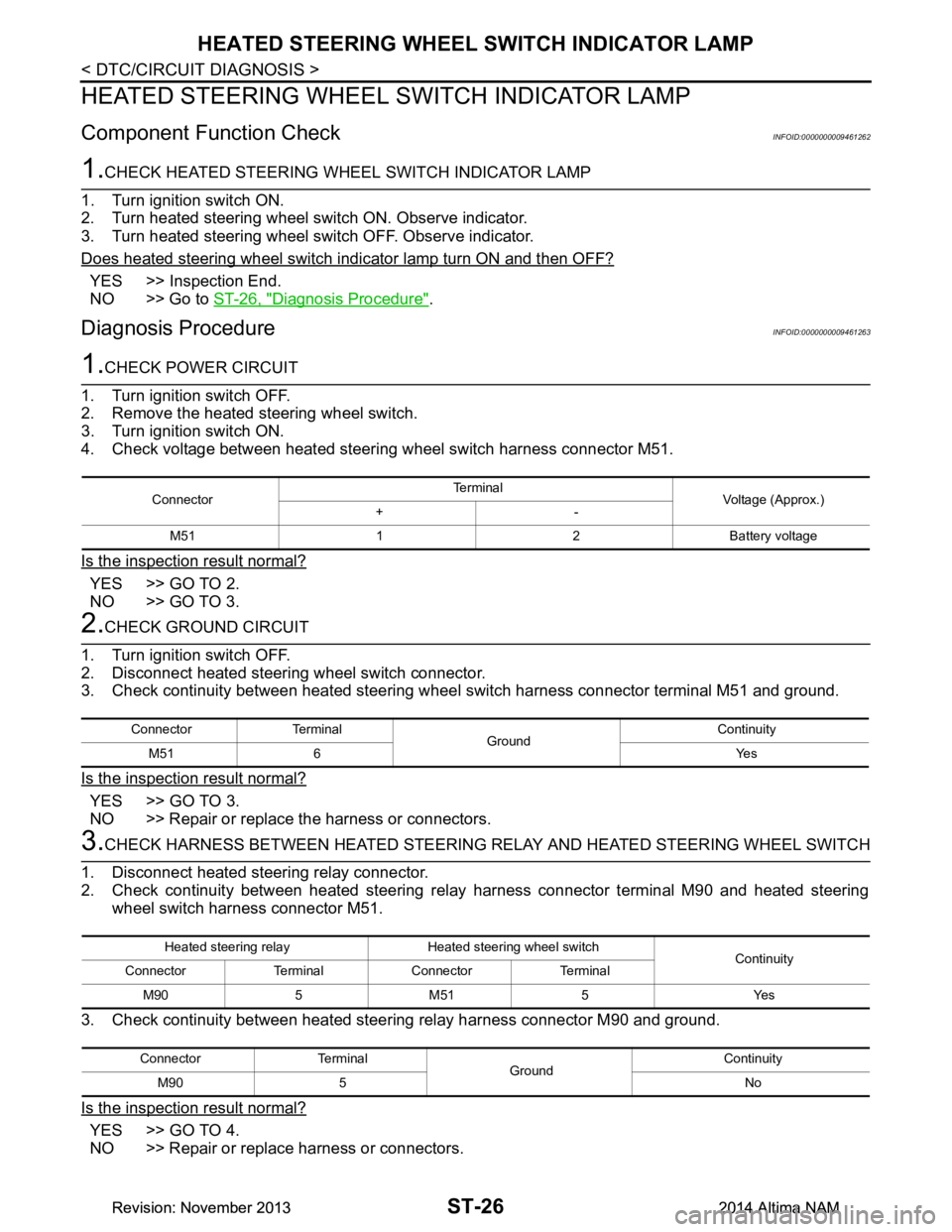
4. Check voltage between heated steering wheel switch harness connector M51.
Is the inspection result normal?
YES >> GO TO 2.
NO >> GO TO 3.
2.CHECK GROUND CIRCUIT
1. Turn ignition switch OFF.
2. Disconnect heated steering wheel switch connector.
3. Check continuity between heated steering wheel switch harness connector terminal M51 and ground.
Is the inspection result normal?
YES >> GO TO 3.
NO >> Repair or replace the harness or connectors.
3.CHECK HARNESS BETWEEN HEATED STEERING RELAY AND HEATED STEERING WHEEL SWITCH
1. Disconnect heated steering relay connector.
2. Check continuity between heated steering rela y harness connector terminal M90 and heated steering
wheel switch harness connector M51.
3. Check continuity between heated steer ing relay harness connector M90 and ground.
Is the inspection result normal?
YES >> GO TO 4.
NO >> Repair or replace harness or connectors.
Connector Te r m i n a l
Voltage (Approx.)
+-
M51 1 2 Battery voltage
Connector Terminal GroundContinuity
M51 6 Yes
Heated steering relay Heated steering wheel switch Continuity
Connector Terminal Connector Terminal
M90 5 M51 5 Yes
Connector Terminal GroundContinuity
M90 5 No
Revision: November 20132014 Altima NAMRevision: November 20132014 Altima NAM
Page 4130 of 4801
HEATED STEERING WHEEL SWITCH INDICATOR LAMPST-27
< DTC/CIRCUIT DIAGNOSIS >
C
D E
F
H I
J
K L
M A
B
ST
N
O P
4.CHECK HEATED STEERING RELAY
Check heated steering relay. Refer to ST-24, "Component Inspection (Heated Steering Relay)"
.
Is the inspection result normal?
YES >> GO TO 5.
NO >> Replace heated steering relay.
5.CHECK BATTERY POWER
Check the following:
•Battery
• Harness for open or short between battery and 10A fuse (No. 2)
• 10A fuse (No. 2)
• Harness for open or short between 10A fuse (No. 2) and heated steering wheel relay
Is the inspection result normal?
YES >> GO TO 6.
NO >> Repair harness or connector.
6.CHECK HARNESS BETWEEN A/C AUTO AMP. AND HEATED STEERING WHEEL SWITCH
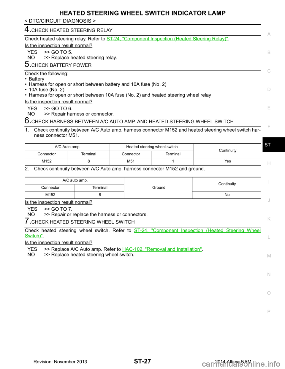
1. Check continuity between A/C Auto amp. harne ss connector M152 and heated steering wheel switch har-
ness connector M51.
2. Check continuity between A/C Auto amp. harness connector M152 and ground.
Is the inspection result normal?
YES >> GO TO 7.
NO >> Repair or replace the harness or connectors.
7.CHECK HEATED STEERING WHEEL SWITCH
Check heated steering wheel switch. Refer to ST-24, "Component Inspection (Heated Steering Wheel
Switch)".
Is the inspection result normal?
YES >> Replace A/C Auto amp. Refer to HAC-102, "Removal and Installation".
NO >> Replace heated steering wheel switch.
A/C Auto amp. Heated steering wheel switch Continuity
Connector Terminal Connector Terminal
M152 8 M51 1 Yes
A/C auto amp. GroundContinuity
Connector Terminal
M152 8 No
Revision: November 20132014 Altima NAMRevision: November 20132014 Altima NAM
Page 4133 of 4801
ST-30
< PERIODIC MAINTENANCE >
POWER STEERING FLUID
PERIODIC MAINTENANCE
POWER STEERING FLUID
Draining and RefillingINFOID:0000000009461266
DRAINING
1. Disconnect the high and low pressure piping from power steering gear.
2. Drain power steering fluid into a suitable container.
REFILLING
1. Fill power steering reservoir while checking power steering fluid level.
2. Bleed air from power steering hydraulic system. Refer to ST-30, "Air Bleeding Hydraulic System"
.
3. Check for power steering fluid leaks.
Air Bleeding Hydraulic SystemINFOID:0000000009461267
AIR BLEEDING HYDRAULIC SYSTEM
If air bleeding is not complete, excessive noise in the power steering oil pump will be present.
1. Make sure engine is off.
2. Turn the steering wheel from the full right stop pos ition and then to full left stop position several times.
Repeat until bubbles are no longer being generated in the reservoir.
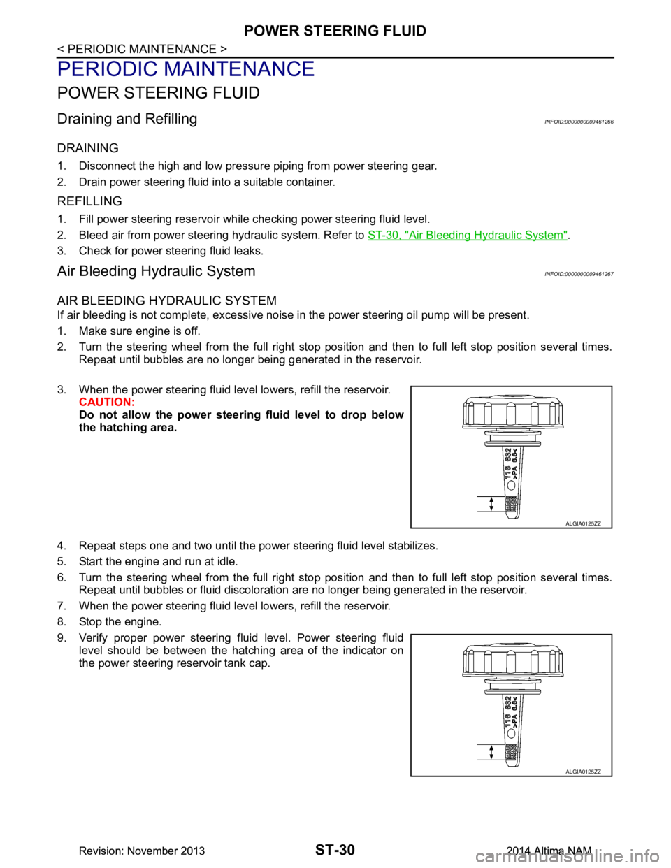
3. When the power steering fluid level lowers, refill the reservoir. CAUTION:
Do not allow the power steerin g fluid level to drop below
the hatching area.
4. Repeat steps one and two until the power steering fluid level stabilizes.
5. Start the engine and run at idle.
6. Turn the steering wheel from the full right stop pos ition and then to full left stop position several times.
Repeat until bubbles or fluid discoloration are no longer being generated in the reservoir.
7. When the power steering fluid level lowers, refill the reservoir.
8. Stop the engine.
9. Verify proper power steering fluid level. Power steering fluid level should be between the hatching area of the indicator on
the power steering reservoir tank cap.
ALGIA0125ZZ
ALGIA0125ZZ
Revision: November 20132014 Altima NAMRevision: November 20132014 Altima NAM
Page 4139 of 4801
ST-36
< REMOVAL AND INSTALLATION >
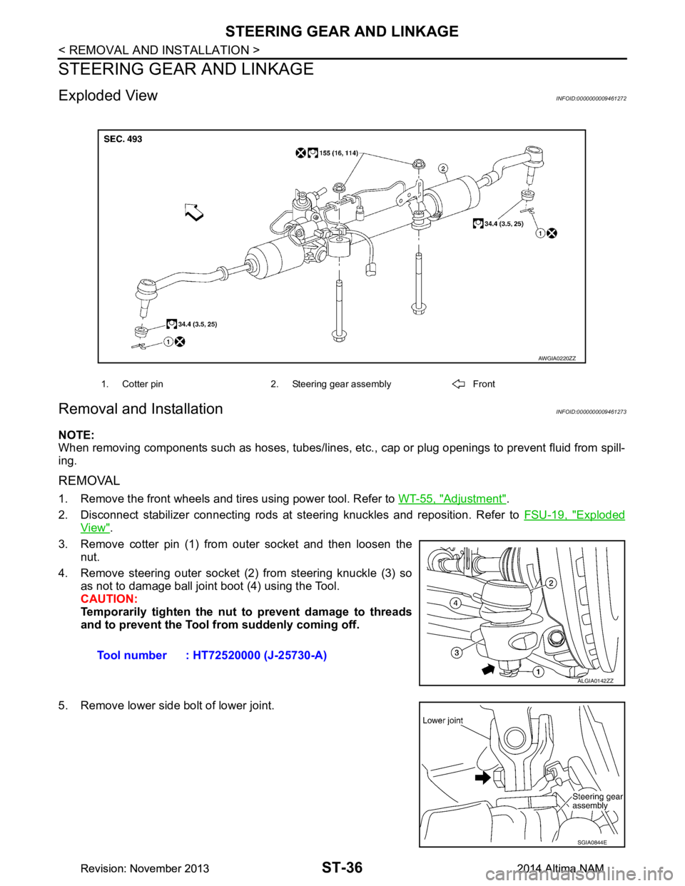
STEERING GEAR AND LINKAGE
STEERING GEAR AND LINKAGE
Exploded ViewINFOID:0000000009461272
Removal and InstallationINFOID:0000000009461273
NOTE:
When removing components such as hoses, tubes/lines, etc. , cap or plug openings to prevent fluid from spill-
ing.
REMOVAL
1. Remove the front wheels and tires using power tool. Refer to WT-55, "Adjustment".
2. Disconnect stabilizer connecting rods at st eering knuckles and reposition. Refer to FSU-19, "Exploded
View".
3. Remove cotter pin (1) from outer socket and then loosen the nut.
4. Remove steering outer socket (2) from steering knuckle (3) so as not to damage ball joint boot (4) using the Tool.
CAUTION:
Temporarily tighten the nut to prevent damage to threads
and to prevent the Tool fr om suddenly coming off.
5. Remove lower side bolt of lower joint.
1. Cotter pin 2. Steering gear assembly Front
AWGIA0220ZZ
Tool number : HT72520000 (J-25730-A)
ALGIA0142ZZ
SGIA0844E
Revision: November 20132014 Altima NAMRevision: November 20132014 Altima NAM
Page 4141 of 4801
ST-38
< REMOVAL AND INSTALLATION >
POWER STEERING OIL PUMP
POWER STEERING OIL PUMP
Exploded ViewINFOID:0000000009461274
Removal and InstallationINFOID:0000000009461275
NOTE:
When removing components such as hoses, tubes/lines, etc. , cap or plug openings to prevent fluid from spill-
ing.
REMOVAL
1. Remove the power steering oil pump cover (1).
2. Drain power steering fluid. Refer to ST-30, "Draining and Refilling"
.
3. Remove the bolt from the power steering pressure line bracket.
1. Power steering reservoir cap 2. Power steering oil pump assembly 3. Low pressure piping
4. High pressure piping Front
ALGIA0145GB
ALGIA0132ZZ
Revision: November 20132014 Altima NAMRevision: November 20132014 Altima NAM
Page 4142 of 4801
POWER STEERING OIL PUMPST-39
< REMOVAL AND INSTALLATION >
C
D E
F
H I
J
K L
M A
B
ST
N
O P
4. Disconnect the following components from the power steering oil pump:
• LH power steering pump connector (A).
• Reservoir hose (B).
• RH power steering pump connector (C).
• High pressure piping (D).
5. Remove power steering oil pump bolts, then remove power steering oil pump.
INSTALLATION
Installation is in the reverse order of removal.
1. Install power steering pressure line to power steering oil pump. • Install power steering pressure line hold down bolt hand tight.
• Install power steering pressure line bracket and tighten to specified torque.
• Tighten power steering pressure line hold down bolt to specified torque.
2. Bleed air from power steering system. CAUTION:
Do not reuse O-rings.
ALGIA0148ZZ
Revision: November 20132014 Altima NAMRevision: November 20132014 Altima NAM
Page 4143 of 4801
ST-40
< REMOVAL AND INSTALLATION >
HYDRAULIC LINE
HYDRAULIC LINE
Exploded ViewINFOID:0000000009461276
QR25DE
ALGIA0133GB
1. Power steering pump assembly 2. High pressure piping (upper) 3. High pressure piping (lower)
4. Power steering gear assembly 5. Low pressure piping (lower) 6. Low pressure piping (upper)
A. View A B. View B Front
Revision: November 20132014 Altima NAMRevision: November 20132014 Altima NAM