2014 NISSAN TEANA SEC
[x] Cancel search: SECPage 4184 of 4801

HYDRAULIC PUMP ELECTRIC POWER STEERING WARNING LAMP DOES
NOT TURN OFF
STC-33
< SYMPTOM DIAGNOSIS >
C
D E
F
H I
J
K L
M A
B
STC
N
O P
HYDRAULIC PUMP ELECTRIC POWER STEERING WARNING LAMP
DOES NOT TURN OFF
DescriptionINFOID:0000000009460374
Hydraulic pump electric power steering warning lamp does not turn OFF several seconds after engine started
Diagnosis ProcedureINFOID:0000000009460375
1.PERFORM SELF-DIAGNOSIS
With CONSULT
Perform “EPS” self-diagnosis.
Is any DTC detected?
YES >> Check the DTC. Refer to STC-13, "DTC Index".
NO >> GO TO 2.
2.CHECK HYDRAULIC PUMP ELECTRIC POWER STEERING WARNING LAMP
Perform the trouble diagnosis of hydraulic pump el ectric power steering warning lamp. Refer to STC-31,
"Diagnosis Procedure".
Is the inspection result normal?
YES >> GO TO 3.
NO >> Repair or replace the malfunctioning components.
3.POWER STEERING CONT ROL MODULE POWER SUPPLY AND GROUND CIRCUIT
Perform the trouble diagnosis of power steering control module power supply and ground. Refer to STC-23,
"Diagnosis Procedure".
Is the inspection result normal?
YES >> Check that the pin terminals and t he connection of each connector are normal.
NO >> Repair or replace the malfunctioning components.
Revision: November 20132014 Altima NAMRevision: November 20132014 Altima NAM
Page 4191 of 4801

STR-1
ENGINE
C
D E
F
G H
I
J
K L
M
SECTION STR
A
STR
N
O P
CONTENTS
STARTING SYSTEM
PRECAUTION ................ ...............................2
PRECAUTIONS .............................................. .....2
Precaution for Supplemental Restraint System
(SRS) "AIR BAG" and "SEAT BELT PRE-TEN-
SIONER" ............................................................. ......
2
PREPARATION ............................................3
PREPARATION .............................................. .....3
Special Service Tool ........................................... ......3
Commercial Service Tool ..........................................3
SYSTEM DESCRIPTION ..............................4
COMPONENT PARTS ................................... .....4
QR25DE ................................................................. ......4
QR25DE : Component Parts Location ......................4
QR25DE : Component Description ..........................4
VQ35DE ................................................................. ......4
VQ35DE : Component Parts Location ......................5
VQ35DE : Component Description ...........................5
SYSTEM ..............................................................6
System Diagram .................................................. ......6
System Description ...................................................6
Component Description ............................................6
WIRING DIAGRAM .......................................7
STARTING SYSTEM ...................................... .....7
Wiring Diagram ................................................... ......7
BASIC INSPECTION ...................................12
DIAGNOSIS AND REPAIR WORKFLOW ........12
Work Flow (With GR8-1200 NI) ........................... ....12
Work Flow (Without GR8-1200 NI) ..........................16
DTC/CIRCUIT DIAGNOSIS .........................18
B TERMINAL CIRCUIT .....................................18
Description ........................................................... ....18
Diagnosis Procedure ...............................................18
S CONNECTOR CIRCUIT .................................20
Description ...............................................................20
Diagnosis Procedure ...............................................20
SYMPTOM DIAGNOSIS ..............................21
STARTING SYSTEM .........................................21
Symptom Table ................................................... ....21
REMOVAL AND INSTALLATION ...............22
STARTER MOTOR ...........................................22
QR25DE ................................................................. ....22
QR25DE : Exploded View .......................................22
QR25DE : Removal and Installation ........................22
VQ35DE ................................................................. ....23
VQ35DE : Exploded View ........................................23
VQ35DE : Removal and Installation ........................23
SERVICE DATA AND SPECIFICATIONS
(SDS) ............... .............................................
25
STARTER MOTOR ...........................................25
Starter .................................................................. ....25
Revision: November 20132014 Altima NAMRevision: November 20132014 Altima NAM
Page 4192 of 4801

STR-2
< PRECAUTION >
PRECAUTIONS
PRECAUTION
PRECAUTIONS
Precaution for Supplemental Restraint System (SRS) "AIR BAG" and "SEAT BELT
PRE-TENSIONER"
INFOID:0000000009951694
The Supplemental Restraint System such as “A IR BAG” and “SEAT BELT PRE-TENSIONER”, used along
with a front seat belt, helps to reduce the risk or severi ty of injury to the driver and front passenger for certain
types of collision. Information necessary to service the system safely is included in the SR and SB section of
this Service Manual.
WARNING:
• To avoid rendering the SRS inopera tive, which could increase the risk of personal injury or death in
the event of a collision which would result in air bag inflation, all maintenance must be performed by
an authorized NISS AN/INFINITI dealer.
• Improper maintenance, including in correct removal and installation of the SRS, can lead to personal
injury caused by unintent ional activation of the system. For re moval of Spiral Cable and Air Bag
Module, see the SR section.
• Do not use electrical test equipmen t on any circuit related to the SRS unless instructed to in this
Service Manual. SRS wiring harn esses can be identified by yellow and/or orange harnesses or har-
ness connectors.
PRECAUTIONS WHEN USING POWER TOOLS (AIR OR ELECTRIC) AND HAMMERS
WARNING:
• When working near the Airbag Diagnosis Sensor Unit or other Airbag System sensors with the Igni-
tion ON or engine running, DO NOT use air or electri c power tools or strike near the sensor(s) with a
hammer. Heavy vibration could activate the sensor( s) and deploy the air bag(s), possibly causing
serious injury.
• When using air or electric power tools or hammers , always switch the Ignition OFF, disconnect the
battery and wait at least three minutes before performing any service.
Revision: November 20132014 Altima NAMRevision: November 20132014 Altima NAM
Page 4204 of 4801

STR-14
< BASIC INSPECTION >
DIAGNOSIS AND REPAIR WORKFLOW
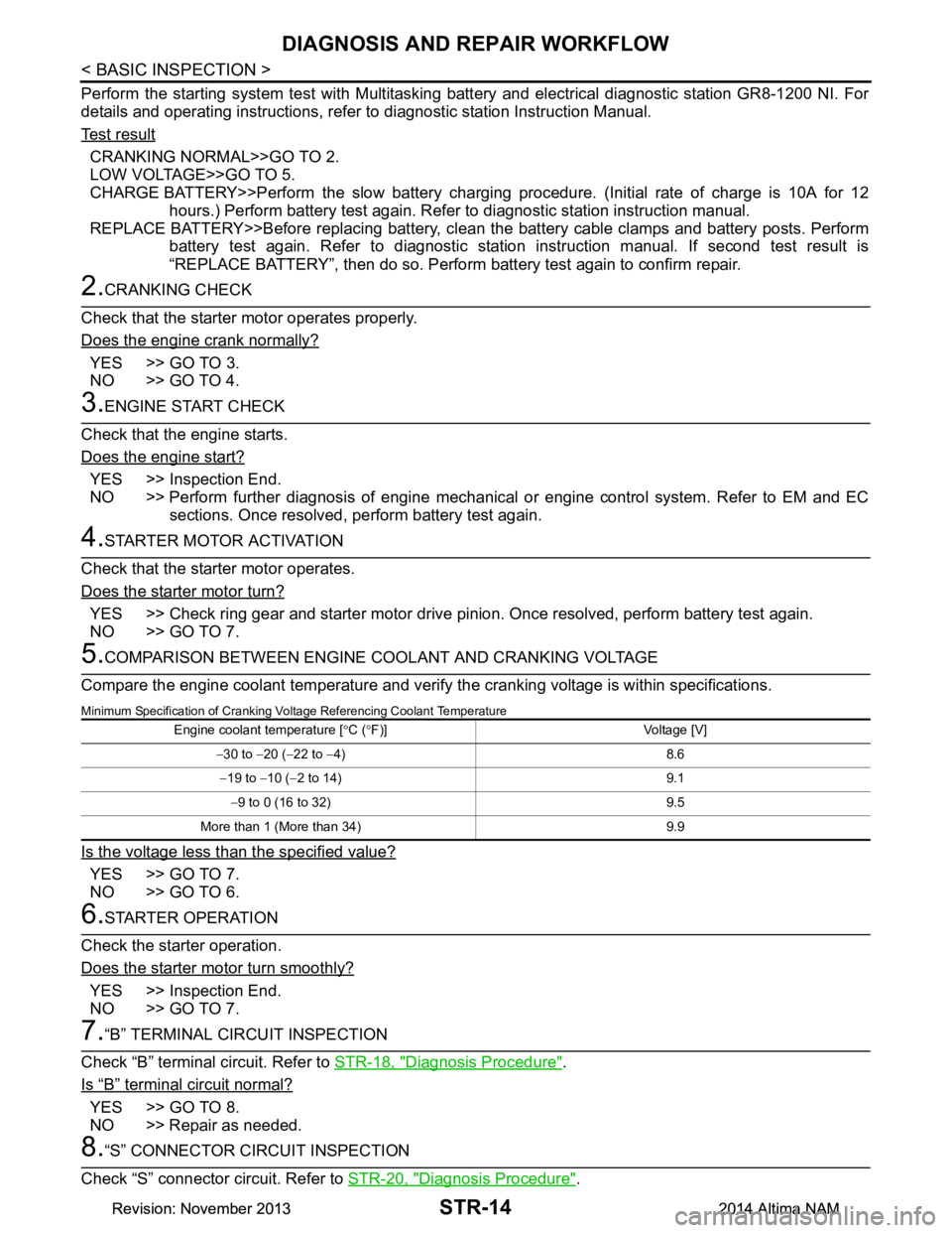
Perform the starting system test with Multitasking battery and electrical diagnostic station GR8-1200 NI. For
details and operating instructions, refer to diagnostic station Instruction Manual.
Te s t r e s u l t
CRANKING NORMAL>>GO TO 2.
LOW VOLTAGE>>GO TO 5.
CHARGE BATTERY>>Perform the slow battery charging procedure. (Initial rate of charge is 10A for 12
hours.) Perform battery test again. Refer to diagnostic station instruction manual.
REPLACE BATTERY>>Before replacing battery, clean t he battery cable clamps and battery posts. Perform
battery test again. Refer to diagnostic station instruction manual. If second test result is
“REPLACE BATTERY”, then do so. Perform battery test again to confirm repair.
2.CRANKING CHECK
Check that the starter motor operates properly.
Does the engine crank normally?
YES >> GO TO 3.
NO >> GO TO 4.
3.ENGINE START CHECK
Check that the engine starts.
Does the engine start?
YES >> Inspection End.
NO >> Perform further diagnosis of engine mechanical or engine control system. Refer to EM and EC sections. Once resolved, perform battery test again.
4.STARTER MOTOR ACTIVATION
Check that the starter motor operates.
Does the starter motor turn?
YES >> Check ring gear and starter motor drive pinion. Once resolved, perform battery test again.
NO >> GO TO 7.
5.COMPARISON BETWEEN ENGINE COOLANT AND CRANKING VOLTAGE
Compare the engine coolant temperature and verify the cranking voltage is within specifications.
Minimum Specification of Cranking Voltage Referencing Coolant Temperature
Is the voltage less than the specified value?
YES >> GO TO 7.
NO >> GO TO 6.
6.STARTER OPERATION
Check the starter operation.
Does the starter motor turn smoothly?
YES >> Inspection End.
NO >> GO TO 7.
7.“B” TERMINAL CIRCUIT INSPECTION
Check “B” terminal circuit. Refer to STR-18, "Diagnosis Procedure"
.
Is
“B” terminal circuit normal?
YES >> GO TO 8.
NO >> Repair as needed.
8.“S” CONNECTOR CIRCUIT INSPECTION
Check “S” connector circuit. Refer to STR-20, "Diagnosis Procedure"
.
Engine coolant temperature [°C ( °F)] Voltage [V]
− 30 to −20 ( −22 to −4) 8.6
− 19 to −10 ( −2 to 14) 9.1
− 9 to 0 (16 to 32) 9.5
More than 1 (More than 34) 9.9
Revision: November 20132014 Altima NAMRevision: November 20132014 Altima NAM
Page 4216 of 4801

TM-1
TRANSMISSION & DRIVELINE
CEF
G H
I
J
K L
M
SECTION TM
A
B
TM
N
O P
CONTENTS
TRANSAXLE & TRANSMISSION
CVT: RE0F10D
PRECAUTION ................ ...............................
9
PRECAUTIONS .............................................. .....9
Precaution for Supplemental Restraint System
(SRS) "AIR BAG" and "SEAT BELT PRE-TEN-
SIONER" ............................................................. ......
9
Precaution for Procedure without Cowl Top Cover ......9
Precaution for TCM and Transaxle Assembly Re-
placement ............................................................ ......
9
General Precautions ...............................................10
On Board Diagnosis (OBD) System of CVT and
Engine ................................................................. ....
11
Removal and Installation Procedure for CVT Unit
Connector ............................................................ ....
11
PREPARATION ...........................................13
PREPARATION .............................................. ....13
Special Service Tools .......................................... ....13
Commercial Service Tools ......................................13
SYSTEM DESCRIPTION .............................14
COMPONENT PARTS ................................... ....14
CVT CONTROL SYSTEM .........................................14
CVT CONTROL SYSTEM : Component Parts Lo-
cation ................................................................... ....
14
CVT CONTROL SYSTEM : TCM ............................16
CVT CONTROL SYSTEM : Transmission Range
Switch .................................................................. ....
16
CVT CONTROL SYSTEM : Primary Speed Sen-
sor ....................................................................... ....
16
CVT CONTROL SYSTEM : Output Speed Sensor ....16
CVT CONTROL SYSTEM : In put Speed Sensor ....17
CVT CONTROL SYSTEM : CVT Fluid Tempera-
ture Sensor .......................................................... ....
17
CVT CONTROL SYSTEM : Primary Pressure
Sensor ................................................................. ....
18
CVT CONTROL SYSTEM : Secondary Pressure
Sensor ................................................................. ....
18
CVT CONTROL SYSTEM : Primary Pressure So-
lenoid Valve ......................................................... ....
19
CVT CONTROL SYSTEM : Secondary Pressure
Solenoid Valve ..................................................... ....
19
CVT CONTROL SYSTEM : Select Solenoid Valve
....
19
CVT CONTROL SYSTEM : Torque Converter
Clutch Solenoid Valve ......................................... ....
19
CVT CONTROL SYSTEM : Line Pressure Sole-
noid Valve ............................................................ ....
20
CVT CONTROL SYSTEM : Overdrive Control
Switch .................................................................. ....
20
CVT CONTROL SYSTEM : O/D OFF Indicator
Lamp .................................................................... ....
20
CVT CONTROL SYSTEM : Shift Position Indica-
tor ........................................................................ ....
20
SHIFT LOCK SYSTEM ..............................................20
SHIFT LOCK SYSTEM : Component Parts Loca-
tion ....................................................................... ....
21
STRUCTURE AND OPERATION .....................22
TRANSAXLE .......................................................... ....22
TRANSAXLE : Cross-Sectional View ......................22
TRANSAXLE : Operation Stat us .............................23
TRANSAXLE : Transaxle Me chanism .....................23
TRANSAXLE : Oil Pressure System .......................26
TRANSAXLE : Component De scription ...................27
FLUID COOLER & FLUID WARMER SYSTEM .... ....27
FLUID COOLER & FLUID WARMER SYSTEM :
System Description .............................................. ....
28
SHIFT LOCK SYSTEM ..............................................28
SHIFT LOCK SYSTEM : Syst em Description ..........28
SYSTEM ...................... ......................................30
CVT CONTROL SYSTEM ..... .....................................30
CVT CONTROL SYSTEM : S ystem Description .....30
Revision: November 20132014 Altima NAMRevision: November 20132014 Altima NAM
Page 4220 of 4801

TM-5
CEF
G H
I
J
K L
M A
B
TM
N
O P
General Specification ..........................................
..
212
Shift Characteristics ..............................................212
Stall Speed ............................................................212
Torque Converter ..................................................212
Heater Thermostat ................................................212
CVT: RE0F10E
PRECAUTION ................ ............................
213
PRECAUTIONS .............................................. ..213
Precaution for Supplemental Restraint System
(SRS) "AIR BAG" and "SEAT BELT PRE-TEN-
SIONER" ............................................................. ..
213
Precaution for Procedure without Cowl Top Cover ..213
Precaution for TCM and Transaxle Assembly Re-
placement ............................................................ ..
213
General Precautions .............................................214
On Board Diagnosis (OBD) System of CVT and
Engine ................................................................. ..
215
Removal and Installation Procedure for CVT Unit
Connector ............................................................ ..
215
PREPARATION .........................................217
PREPARATION .............................................. ..217
Special Service Tools .......................................... ..217
Commercial Service Tools ....................................217
SYSTEM DESCRIPTION ...........................218
COMPONENT PARTS ................................... ..218
CVT CONTROL SYSTEM .......................................218
CVT CONTROL SYSTEM : Component Parts Lo-
cation ................................................................... ..
218
CVT CONTROL SYSTEM : TCM ..........................219
CVT CONTROL SYSTEM : Transmission Range
Switch .................................................................. ..
219
CVT CONTROL SYSTEM : Primary Speed Sen-
sor ....................................................................... ..
219
CVT CONTROL SYSTEM : Output Speed Sensor ..220
CVT CONTROL SYSTEM : Input Speed Sensor ..220
CVT CONTROL SYSTEM : CVT Fluid Tempera-
ture Sensor .......................................................... ..
221
CVT CONTROL SYSTEM : Primary Pressure
Sensor ................................................................. ..
221
CVT CONTROL SYSTEM : Secondary Pressure
Sensor ................................................................. ..
222
CVT CONTROL SYSTEM : Primary Pressure So-
lenoid Valve ......................................................... ..
222
CVT CONTROL SYSTEM : Secondary Pressure
Solenoid Valve .................................................... ..
222
CVT CONTROL SYSTEM : Select Solenoid Valve
..
223
CVT CONTROL SYSTEM : Torque Converter
Clutch Solenoid Valve ......................................... ..
223
CVT CONTROL SYSTEM : Line Pressure Sole-
noid Valve ........................................................... ..
223
CVT CONTROL SYSTEM : Paddle Shifter ...........223
CVT CONTROL SYSTEM : Shift Position Indica-
tor ........................................................................ ..
223
SHIFT LOCK SYSTEM ............................................223
SHIFT LOCK SYSTEM : Component Parts Loca-
tion ....................................................................... ..
224
STRUCTURE AND OPERATION ...................225
TRANSAXLE .......................................................... ..225
TRANSAXLE : Cross-Sectional View ....................225
TRANSAXLE : Operation Stat us ...........................226
TRANSAXLE : Transaxle Me chanism ...................226
TRANSAXLE : Oil Pressure System .....................228
TRANSAXLE : Component De scription .................229
FLUID COOLER & FLUID WARMER SYSTEM .... ..229
FLUID COOLER & FLUID WARMER SYSTEM :
System Description .............................................. ..
230
SHIFT LOCK SYSTEM ............................................230
SHIFT LOCK SYSTEM : Syst em Description ........230
SYSTEM ...................... ....................................232
CVT CONTROL SYSTEM ..... ...................................232
CVT CONTROL SYSTEM : S ystem Description ...232
CVT CONTROL SYSTEM : Fa il-safe ....................233
CVT CONTROL SYSTEM : Pr otection Control .....236
LINE PRESSURE CONTROL ......................... .........237
LINE PRESSURE CONTROL : System Descrip-
tion ....................................................................... ..
237
SHIFT CONTROL .................................................. ..237
SHIFT CONTROL : System Description ................238
SELECT CONTROL ............................................... ..239
SELECT CONTROL : System Description ............239
LOCK-UP CONTROL ............................................ ..240
LOCK-UP CONTROL : System Description ..........240
ON BOARD DIAGNOSTIC (OBD) SYSTEM ..242
Description .............................................................242
Function of OBD ....................................................242
DIAGNOSIS SYSTEM (TCM) ..........................243
DIAGNOSIS DESCRIPTION .................................. ..243
DIAGNOSIS DESCRIPTION : 1 Trip Detection Di-
agnosis and 2 Trip Detection Diagnosis .............. ..
243
DIAGNOSIS DESCRIPTION : DTC and DTC of
1st Trip ................................................................. ..
243
DIAGNOSIS DESCRIPTION : Malfunction Indica-
tor Lamp (MIL) ..................................................... ..
243
DIAGNOSIS DESCRIPTION : Counter System ....243
CONSULT Function ............................................. ..245
ECU DIAGNOSIS INFORMATION ............251
TCM .................................................................251
Reference Value .................................................. ..251
Revision: November 20132014 Altima NAMRevision: November 20132014 Altima NAM
Page 4224 of 4801
![NISSAN TEANA 2014 Service Manual
PRECAUTIONSTM-9
< PRECAUTION > [CVT: RE0F10D]
C
EF
G H
I
J
K L
M A
B
TM
N
O P
PRECAUTION
PRECAUTIONS
Precaution for Supplemental Restraint System (SRS) "AIR BAG" and "SEAT BELT
PRE-TENSIONER"
INFO NISSAN TEANA 2014 Service Manual
PRECAUTIONSTM-9
< PRECAUTION > [CVT: RE0F10D]
C
EF
G H
I
J
K L
M A
B
TM
N
O P
PRECAUTION
PRECAUTIONS
Precaution for Supplemental Restraint System (SRS) "AIR BAG" and "SEAT BELT
PRE-TENSIONER"
INFO](/manual-img/5/57390/w960_57390-4223.png)
PRECAUTIONSTM-9
< PRECAUTION > [CVT: RE0F10D]
C
EF
G H
I
J
K L
M A
B
TM
N
O P
PRECAUTION
PRECAUTIONS
Precaution for Supplemental Restraint System (SRS) "AIR BAG" and "SEAT BELT
PRE-TENSIONER"
INFOID:0000000009951696
The Supplemental Restraint System such as “A IR BAG” and “SEAT BELT PRE-TENSIONER”, used along
with a front seat belt, helps to reduce the risk or severi ty of injury to the driver and front passenger for certain
types of collision. Information necessary to service t he system safely is included in the SR and SB section of
this Service Manual.
WARNING:
• To avoid rendering the SRS inoper ative, which could increase the risk of personal injury or death in
the event of a collision which would result in air bag inflation, all maintenance must be performed by
an authorized NISSAN/INFINITI dealer.
• Improper maintenance, including in correct removal and installation of the SRS, can lead to personal
injury caused by unintentional act ivation of the system. For removal of Spiral Cable and Air Bag
Module, see the SR section.
• Do not use electrical test equipm ent on any circuit related to the SRS unless instructed to in this
Service Manual. SRS wiring harnesses can be identi fied by yellow and/or orange harnesses or har-
ness connectors.
PRECAUTIONS WHEN USING POWER TOOLS (AIR OR ELECTRIC) AND HAMMERS
WARNING:
• When working near the Airbag Diagnosis Sensor Un it or other Airbag System sensors with the Igni-
tion ON or engine running, DO NOT use air or el ectric power tools or strike near the sensor(s) with a
hammer. Heavy vibration could activate the sensor( s) and deploy the air bag(s), possibly causing
serious injury.
• When using air or electric power tools or hammers , always switch the Ignition OFF, disconnect the
battery and wait at least three mi nutes before performing any service.
Precaution for Procedure without Cowl Top CoverINFOID:0000000009463955
When performing the procedure after removing cowl top cover, cover
the lower end of windshield with urethane, etc to prevent damage to
windshield.
Precaution for TCM and Tran saxle Assembly ReplacementINFOID:0000000009463956
CAUTION:
• To replace TCM, refer to TM-80, "Description"
.
• To replace transaxle assembly, refer to TM-81, "Description"
.
PIIB3706J
Revision: November 20132014 Altima NAMRevision: November 20132014 Altima NAM
Page 4226 of 4801
![NISSAN TEANA 2014 Service Manual
PRECAUTIONSTM-11
< PRECAUTION > [CVT: RE0F10D]
C
EF
G H
I
J
K L
M A
B
TM
N
O P
On Board Diagnosis (OBD) System of CVT and EngineINFOID:0000000009463958
The TCM and ECM have an on board diagnostic s NISSAN TEANA 2014 Service Manual
PRECAUTIONSTM-11
< PRECAUTION > [CVT: RE0F10D]
C
EF
G H
I
J
K L
M A
B
TM
N
O P
On Board Diagnosis (OBD) System of CVT and EngineINFOID:0000000009463958
The TCM and ECM have an on board diagnostic s](/manual-img/5/57390/w960_57390-4225.png)
PRECAUTIONSTM-11
< PRECAUTION > [CVT: RE0F10D]
C
EF
G H
I
J
K L
M A
B
TM
N
O P
On Board Diagnosis (OBD) System of CVT and EngineINFOID:0000000009463958
The TCM and ECM have an on board diagnostic system. It will light up the malfunction indicator lamp (MIL) to
warn the driver of a malfunction causing emission deterioration.
CAUTION:
• Be sure to turn the ignition switch OFF and di sconnect the battery cable from the negative terminal
before any repair or inspection work. The open/s hort circuit of related switches, sensors, solenoid
valves, etc. will cause the MIL to light up.
• Be sure to connect and lock the connectors secure ly after work. A loose (unlocked) connector will
cause the MIL to light up due to an open circuit. (Be sure the connector is free from water, grease,
dirt, bent terminals, etc.)
• Be sure to route and secure the harnesses properly after work. Interference of the harness with a
bracket, etc. may cause the MIL to light up due to a short circuit.
• Be sure to connect rubber tubes properly afte r work. A misconnected or disconnected rubber tube
may cause the MIL to light up due to a malfunction of the EGR system or fuel injection system, etc.
• Be sure to erase the unnecessary malfunction informa tion (repairs completed) from the TCM and
ECM before returning the vehicle to the customer.
Removal and Installation Proc edure for CVT Unit ConnectorINFOID:0000000009463959
REMOVAL
• Rotate bayonet ring (1) counterclockwise. Pull out CVT unit har-
ness connector (2) upward and remove it.
INSTALLATION
1. Align marking (A) on CVT unit harness connector terminal with
marking (B) on bayonet ring. Insert CVT unit harness connector.
2. Rotate bayonet ring clockwise.
3. Rotate bayonet ring clockwise until marking (A) on CVT unit har- ness connector terminal body is aligned with the slit (B) on bayo-
net ring as shown in the figure (correctly fitting condition).
CAUTION:
SCIA6685J
JPDIA0294ZZ
JPDIA0295ZZ
Revision: November 20132014 Altima NAMRevision: November 20132014 Altima NAM