Page 2286 of 4801

EXL-20
< SYSTEM DESCRIPTION >
DIAGNOSIS SYSTEM (BCM)
COMB SW
COMB SW : CONSULT Function (BCM - COMB SW)INFOID:0000000009956484
CAUTION:
After disconnecting the CONSULT vehicle interface (VI) from the data link connector, the ignition must
be cycled OFF → ON (for at least 5 seconds) → OFF. If this step is not performed, the BCM may not go
to ”sleep mode”, potentially causing a di scharged battery and a no-start condition.
DATA MONITOR
BATTERY SAVER
BATTERY SAVER : CONSULT Function (BCM - BATTERY SAVER)INFOID:0000000009956486
CAUTION:
After disconnecting the CONSULT vehicle interface (VI) from the data link connector, the ignition must
be cycled OFF → ON (for at least 5 seconds) → OFF. If this step is not performed, the BCM may not go
to ”sleep mode”, potentially causing a di scharged battery and a no-start condition.
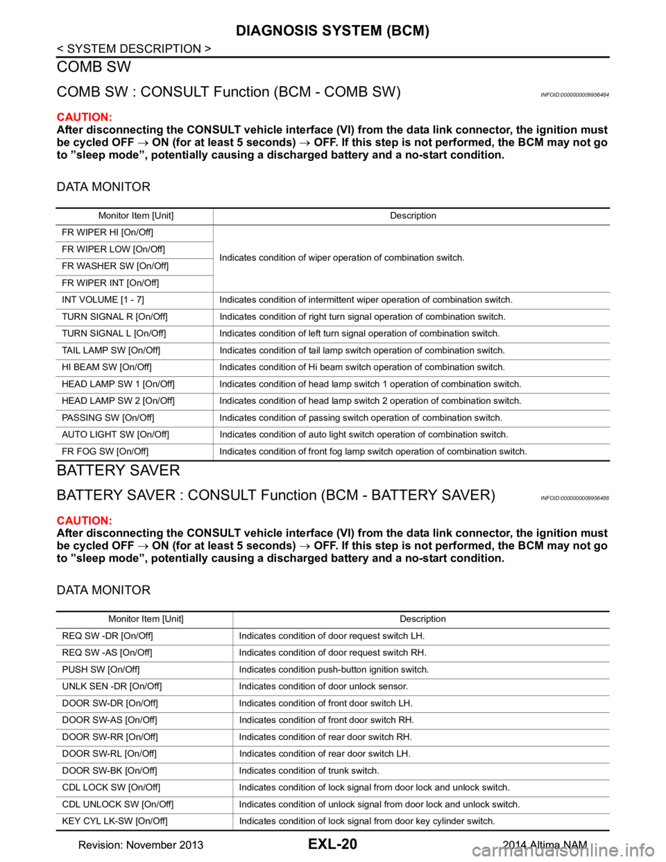
DATA MONITOR
Monitor Item [Unit] Description
FR WIPER HI [On/Off]
Indicates condition of wiper operation of combination switch.
FR WIPER LOW [On/Off]
FR WASHER SW [On/Off]
FR WIPER INT [On/Off]
INT VOLUME [1 - 7] Indicates condition of intermittent wiper operation of combination switch.
TURN SIGNAL R [On/Off] Indicates condition of right turn signal operation of combination switch.
TURN SIGNAL L [On/Off] Indicates condition of left turn signal operation of combination switch.
TAIL LAMP SW [On/Off] Indicates condition of tail lamp switch operation of combination switch.
HI BEAM SW [On/Off] Indicates condition of Hi beam switch operation of combination switch.
HEAD LAMP SW 1 [On/Off] Indicates condition of head lamp switch 1 operation of combination switch.
HEAD LAMP SW 2 [On/Off] Indicates condition of head lamp switch 2 operation of combination switch.
PASSING SW [On/Off] Indicates condition of pass ing switch operation of combination switch.
AUTO LIGHT SW [On/Off] Indicates condition of auto light switch operation of combination switch.
FR FOG SW [On/Off] Indicates condition of front fog lamp switch operation of combination switch.
Monitor Item [Unit] Description
REQ SW -DR [On/Off] Indicates condition of door request switch LH.
REQ SW -AS [On/Off] Indicates condition of door request switch RH.
PUSH SW [On/Off] Indicates condition push-button ignition switch.
UNLK SEN -DR [On/Off] Indicates condition of door unlock sensor.
DOOR SW-DR [On/Off] Indicates condition of front door switch LH.
DOOR SW-AS [On/Off] Indicates condition of front door switch RH.
DOOR SW-RR [On/Off] Indicates condition of rear door switch RH.
DOOR SW-RL [On/Off] Indicates condition of rear door switch LH.
DOOR SW-BK [On/Off] Indicates condition of trunk switch.
CDL LOCK SW [On/Off] Indicates condition of lock signal from door lock and unlock switch.
CDL UNLOCK SW [On/Off] Indicates condition of unlock signal from door lock and unlock switch.
KEY CYL LK-SW [On/Off] Indicates condition of lo ck signal from door key cylinder switch.
Revision: November 20132014 Altima NAMRevision: November 20132014 Altima NAM
Page 2287 of 4801
DIAGNOSIS SYSTEM (BCM)EXL-21
< SYSTEM DESCRIPTION >
C
D E
F
G H
I
J
K
M A
B
EXL
N
O P
ACTIVE TEST
KEY CYL UN-SW [On/Off] Indicates condition of unl ock signal from door key cylinder switch.
TRNK/HAT MNTR [On/Off] Indicates condition of trunk room lamp switch.
RKE-LOCK [On/Off] Indicates condition of lock signal from Intelligent Key.
RKE-UNLOCK [On/Off] Indicates condition of unlock signal from Intelligent Key. Monitor Item [Unit] Description
Test item Description
BATTERY SAVER This test is able to check battery saver operation [On/Off].
Revision: November 20132014 Altima NAMRevision: November 20132014 Altima NAM
Page 2401 of 4801

LICENSE PLATE LAMPEXL-135
< REMOVAL AND INSTALLATION >
C
D E
F
G H
I
J
K
M A
B
EXL
N
O P
LICENSE PLATE LAMP
Removal and InstallationINFOID:0000000009463633
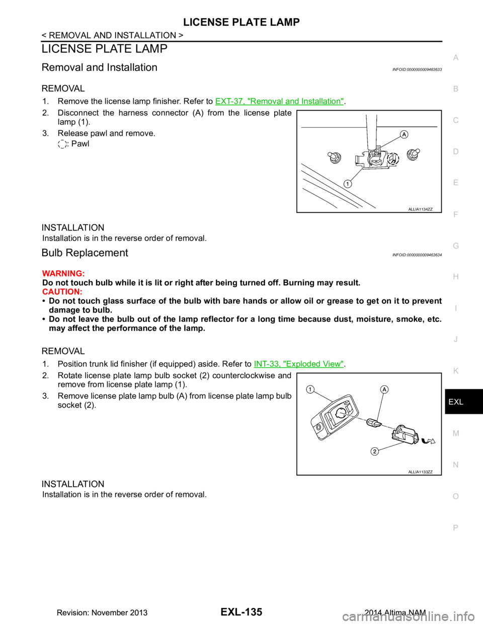
REMOVAL
1. Remove the license lamp finisher. Refer to EXT-37, "Removal and Installation".
2. Disconnect the harness connector (A) from the license plate lamp (1).
3. Release pawl and remove. : Pawl
INSTALLATION
Installation is in the reverse order of removal.
Bulb ReplacementINFOID:0000000009463634
WARNING:
Do not touch bulb while it is lit or right after being turned off. Burning may result.
CAUTION:
• Do not touch glass surface of the bulb with bare hand s or allow oil or grease to get on it to prevent
damage to bulb.
• Do not leave the bulb out of the lamp reflector fo r a long time because dust, moisture, smoke, etc.
may affect the performance of the lamp.
REMOVAL
1. Position trunk lid finisher (if equipped) aside. Refer to INT-33, "Exploded View".
2. Rotate license plate lamp bulb socket (2) counterclockwise and remove from license plate lamp (1).
3. Remove license plate lamp bulb (A) from license plate lamp bulb socket (2).
INSTALLATION
Installation is in the reverse order of removal.
ALLIA1134ZZ
ALLIA1133ZZ
Revision: November 20132014 Altima NAMRevision: November 20132014 Altima NAM
Page 2403 of 4801
REAR COMBINATION LAMPEXL-137
< REMOVAL AND INSTALLATION >
C
D E
F
G H
I
J
K
M A
B
EXL
N
O P
REAR COMBINATION LAMP - LED TYPE
Removal and InstallationINFOID:0000000009463636
Removal
1. Remove trunk rear finisher. Refer to INT-33, "TRUNK LID FINISHER : Removal and Installation".
2. Partially remove trunk side finisher. Refer to INT-34, "TRUNK SIDE FINISHER : Removal and Installa-
tion".
3. Remove the rear combination lamp nuts (B).
4. Disconnect the harness connector (A).
5. Pull the rear combination lamp rearward and remove.
Installation
Installation is the reverse order of removal.
ALLIA1138ZZ
1. Rear combination lamp 2. Rear turn signal lamp bulb 3. Rear combination lamp harness
4. Back-up lamp bulb 5. LED lamp harness connector 6. Side marker lamp bulb
ALLIA1147ZZ
Revision: November 20132014 Altima NAMRevision: November 20132014 Altima NAM
Page 2426 of 4801

EXT-12
< PERIODIC MAINTENANCE >
SQUEAK AND RATTLE TROUBLE DIAGNOSES
INSTRUMENT PANEL
Most incidents are caused by contact and movement between:
1. Cluster lid A and the instrument panel
2. Acrylic lens and combination meter housing
3. Instrument panel to front pillar finisher
4. Instrument panel to windshield
5. Instrument panel pins
6. Wiring harnesses behind the combination meter
7. A/C defroster duct and duct joint
These incidents can usually be located by tapping or moving the components to duplicate the noise or by
pressing on the components while driving to stop the noise. Most of these incidents can be repaired by apply-
ing felt cloth tape or silicone spray (in hard to reach areas). Urethane pads can be used to insulate wiring har-
ness.
CAUTION:
Do not use silicone spray to isolate a squeak or ra ttle. If you saturate the area with silicone, you will
not be able to recheck the repair.
CENTER CONSOLE
Components to pay attention to include:
1. Shift selector assembly cover to finisher
2. A/C control unit and cluster lid C
3. Wiring harnesses behind audio and A/C control unit
The instrument panel repair and isolation pr ocedures also apply to the center console.
DOORS
Pay attention to the:
1. Finisher and inner panel making a slapping noise
2. Inside handle escutcheon to door finisher
3. Wiring harnesses tapping
4. Door striker out of alignment causing a popping noise on starts and stops
Tapping or moving the components or pressing on them wh ile driving to duplicate the conditions can isolate
many of these incidents. You can usually insulate the areas with felt cloth tape or insulator foam blocks from
the NISSAN Squeak and Rattle Kit (J-50397) to repair the noise.
TRUNK
Trunk noises are often caused by a loose jack or loose items put into the trunk by the owner.
In addition look for:
1. Trunk lid bumpers out of adjustment
2. Trunk lid striker out of adjustment
3. The trunk lid torsion bars knocking together
4. A loose license plate or bracket
Most of these incidents can be repaired by adjusting, se curing or insulating the item(s) or component(s) caus-
ing the noise.
SUNROOF/HEADLINING
Noises in the sunroof/headlining area c an often be traced to one of the following:
1. Sunroof lid, rail, linkage or seals making a rattle or light knocking noise
2. Sun visor shaft shaking in the holder
3. Front or rear windshield touching headlining and squeaking
Again, pressing on the components to stop the noise while duplicating the conditions can isolate most of these
incidents. Repairs usually consist of insulating with felt cloth tape.
OVERHEAD CONSOLE (FRONT AND REAR)
Overhead console noises are often caused by the c onsole panel clips not being engaged correctly. Most of
these incidents are repaired by pushing up on the c onsole at the clip locations until the clips engage.
In addition look for:
Revision: November 20132014 Altima NAM
Page 2451 of 4801
LICENSE LAMP FINISHEREXT-37
< REMOVAL AND INSTALLATION >
C
D E
F
G H
I
J
L
M A
B
EXT
N
O P
LICENSE LAMP FINISHER
Removal and InstallationINFOID:0000000009461019
REMOVAL
1. Remove the trunk lid finisher (if equipped). Refer to INT-33, "TRUNK LID FINISHER : Removal and Instal-
lation".
2. Remove the license lamp finisher nuts and bolts.
3. Remove license lamp finisher by pulling toward the rear, then disconnect the harness connector from the trunk opener request switch and remove.
INSTALLATION
Installation is in the reverse order of removal.
1. License lamp finisher
ALKIA2660ZZ
Revision: November 20132014 Altima NAM
Page 2452 of 4801

EXT-38
< REMOVAL AND INSTALLATION >
REAR SPOILER
REAR SPOILER
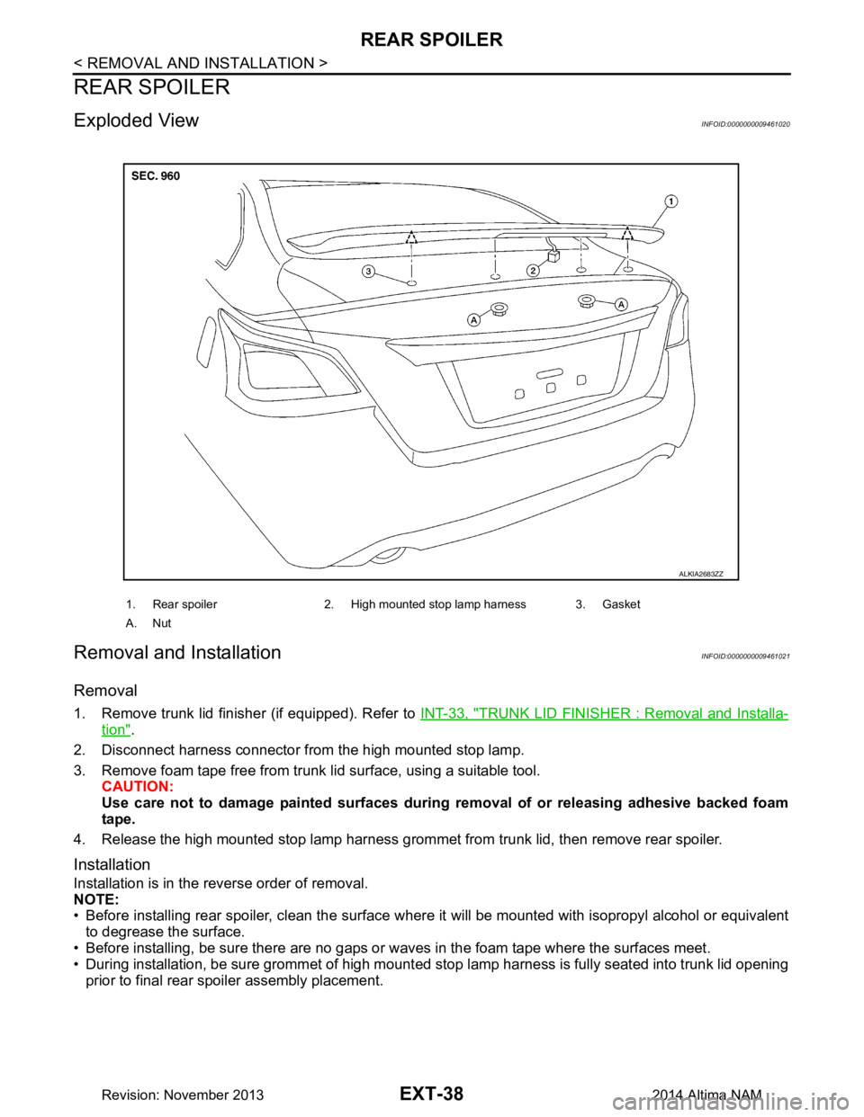
Exploded ViewINFOID:0000000009461020
Removal and InstallationINFOID:0000000009461021
Removal
1. Remove trunk lid finisher (if equipped). Refer to INT-33, "TRUNK LID FINISHER : Removal and Installa-
tion".
2. Disconnect harness connector from the high mounted stop lamp.
3. Remove foam tape free from trunk lid surface, using a suitable tool. CAUTION:
Use care not to damage painted surfaces during removal of or releasing adhesive backed foam
tape.
4. Release the high mounted stop lamp harness grommet from trunk lid, then remove rear spoiler.
Installation
Installation is in the reverse order of removal.
NOTE:
• Before installing rear spoiler, clean the surface w here it will be mounted with isopropyl alcohol or equivalent
to degrease the surface.
• Before installing, be sure there are no gaps or wa ves in the foam tape where the surfaces meet.
• During installation, be sure grommet of high mounted stop lamp harness is fully seated into trunk lid opening
prior to final rear spoiler assembly placement.
1. Rear spoiler 2. High mounted stop lamp harness 3. Gasket
A. Nut
ALKIA2683ZZ
Revision: November 20132014 Altima NAM
Page 2540 of 4801
GI-12
< HOW TO USE THIS MANUAL >
HOW TO READ WIRING DIAGRAMS
• ignition switch is “OFF”,
• doors, hood and trunk lid/back door are closed,
• pedals are not depressed, and
• parking brake is released.
MULTIPLE SWITCH
The continuity of multiple switch is described in two ways as shown below.
• The switch chart is used in schematic diagrams.
• The switch diagram is used in wiring diagrams.
SGI860
JSAIA0017GB
Revision: November 20132014 Altima NAMRevision: November 20132014 Altima NAM