2014 NISSAN TEANA trunk
[x] Cancel search: trunkPage 2926 of 4801

TRUNK ROOM TRIM & TRUNK LID FINISHERINT-35
< REMOVAL AND INSTALLATION >
C
D E
F
G H
I
K L
M A
B
INT
N
O P
INSTALLATION
Installation is in the reverse order of removal.
TRUNK REAR FINISHER
TRUNK REAR FINISHER : Removal and InstallationINFOID:0000000009461369
REMOVAL
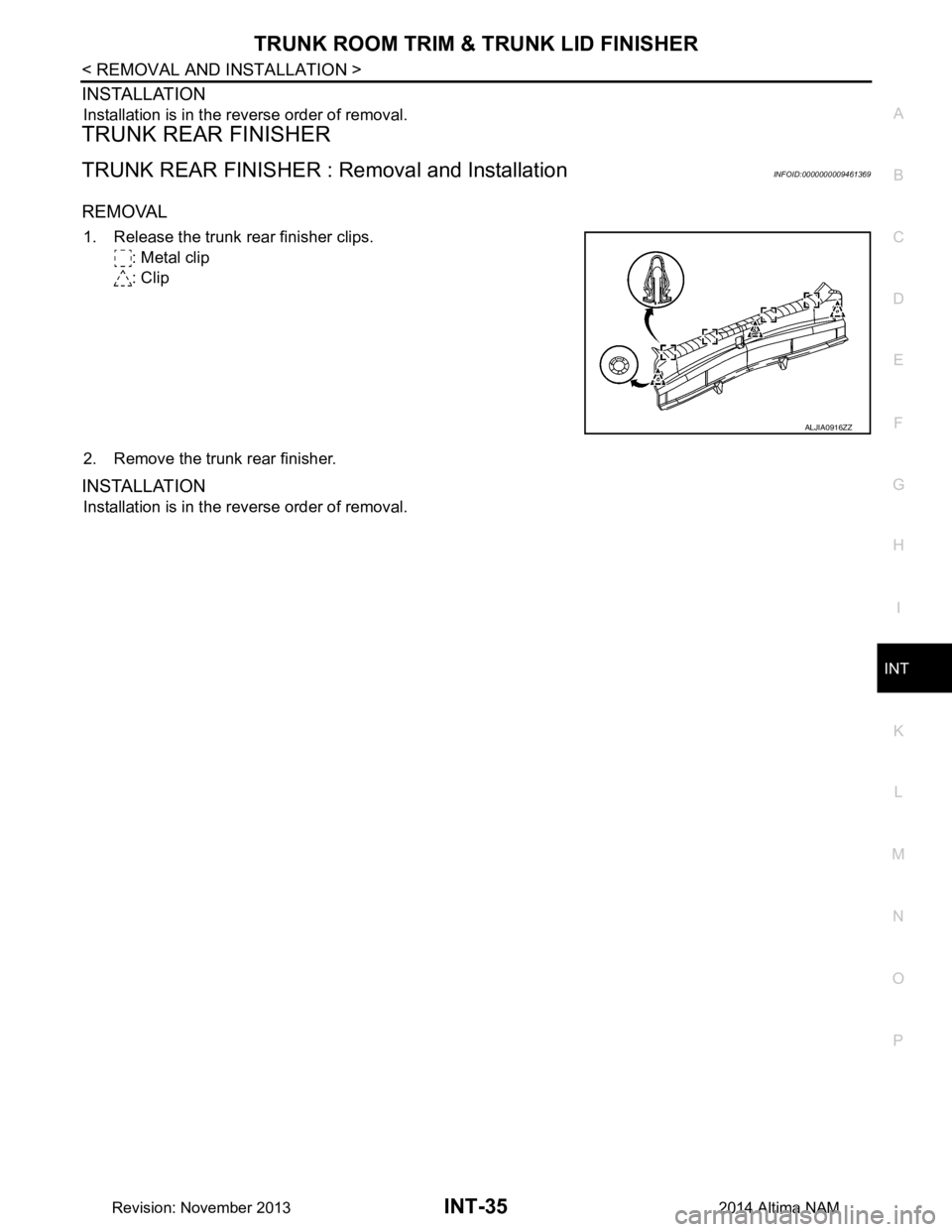
1. Release the trunk rear finisher clips.
: Metal clip
: Clip
2. Remove the trunk rear finisher.
INSTALLATION
Installation is in the reverse order of removal.
ALJIA0916ZZ
Revision: November 20132014 Altima NAM
Page 2936 of 4801

IP-10
< SYMPTOM DIAGNOSIS >
SQUEAK AND RATTLE TROUBLE DIAGNOSES
INSTRUMENT PANEL
Most incidents are caused by contact and movement between:
1. Cluster lid A and the instrument panel
2. Acrylic lens and combination meter housing
3. Instrument panel to front pillar finisher
4. Instrument panel to windshield
5. Instrument panel pins
6. Wiring harnesses behind the combination meter
7. A/C defroster duct and duct joint
These incidents can usually be located by tapping or moving the components to duplicate the noise or by
pressing on the components while driving to stop the noise. Most of these incidents can be repaired by apply-
ing felt cloth tape or silicone spray (in hard to reach areas). Urethane pads can be used to insulate wiring har-
ness.
CAUTION:
Do not use silicone spray to isolate a squeak or ra ttle. If you saturate the area with silicone, you will
not be able to recheck the repair.
CENTER CONSOLE
Components to pay attention to include:
1. Shift selector assembly cover to finisher
2. A/C control unit and cluster lid C
3. Wiring harnesses behind audio and A/C control unit
The instrument panel repair and isolation pr ocedures also apply to the center console.
DOORS
Pay attention to the:
1. Finisher and inner panel making a slapping noise
2. Inside handle escutcheon to door finisher
3. Wiring harnesses tapping
4. Door striker out of alignment causing a popping noise on starts and stops
Tapping or moving the components or pressing on them wh ile driving to duplicate the conditions can isolate
many of these incidents. You can usually insulate the areas with felt cloth tape or insulator foam blocks from
the NISSAN Squeak and Rattle Kit (J-50397) to repair the noise.
TRUNK
Trunk noises are often caused by a loose jack or loose items put into the trunk by the owner.
In addition look for:
1. Trunk lid bumpers out of adjustment
2. Trunk lid striker out of adjustment
3. The trunk lid torsion bars knocking together
4. A loose license plate or bracket
Most of these incidents can be repaired by adjusting, se curing or insulating the item(s) or component(s) caus-
ing the noise.
SUNROOF/HEADLINING
Noises in the sunroof/headlining area c an often be traced to one of the following:
1. Sunroof lid, rail, linkage or seals making a rattle or light knocking noise
2. Sun visor shaft shaking in the holder
3. Front or rear windshield touching headlining and squeaking
Again, pressing on the components to stop the noise while duplicating the conditions can isolate most of these
incidents. Repairs usually consist of insulating with felt cloth tape.
OVERHEAD CONSOLE (FRONT AND REAR)
Overhead console noises are often caused by the c onsole panel clips not being engaged correctly. Most of
these incidents are repaired by pushing up on the c onsole at the clip locations until the clips engage.
In addition look for:
Revision: November 20132014 Altima NAM
Page 2948 of 4801

IP-22
< REMOVAL AND INSTALLATION >
GLOVE BOX ASSEMBLY
GLOVE BOX ASSEMBLY
Removal and InstallationINFOID:0000000009461387
REMOVAL
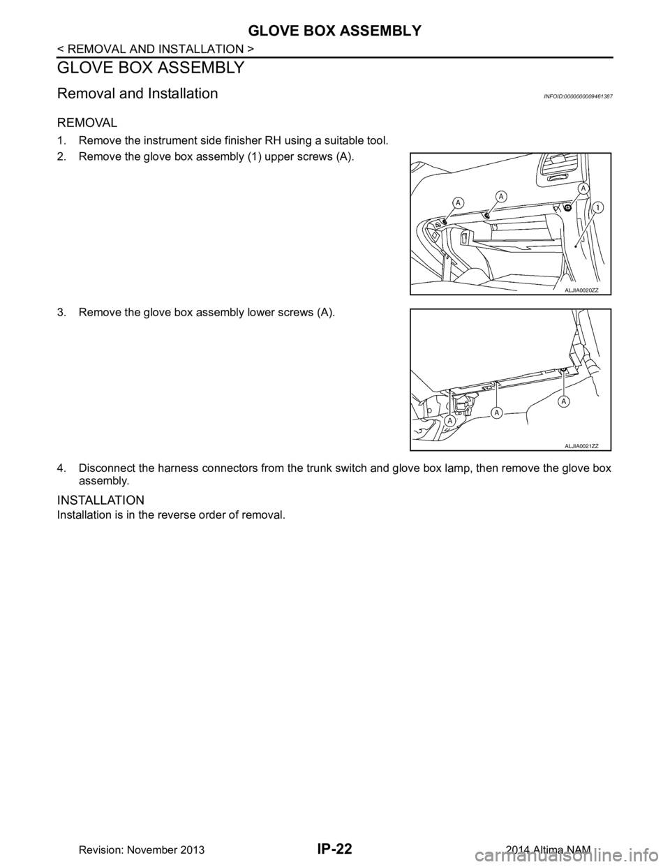
1. Remove the instrument side finisher RH using a suitable tool.
2. Remove the glove box assembly (1) upper screws (A).
3. Remove the glove box assembly lower screws (A).
4. Disconnect the harness connectors from the trunk switch and glove box lamp, then remove the glove box assembly.
INSTALLATION
Installation is in the reverse order of removal.
ALJIA0020ZZ
ALJIA0021ZZ
Revision: November 20132014 Altima NAM
Page 2984 of 4801
![NISSAN TEANA 2014 Service Manual
LAN
SYSTEMLAN-35
< SYSTEM DESCRIPTION > [CAN]
C
D E
F
G H
I
J
K L
B
A
O P
N
*1: QR25DE models
*2: VQ35DE models
*3: With automatic air conditioning system
*4: With manual air conditioning system
NISSAN TEANA 2014 Service Manual
LAN
SYSTEMLAN-35
< SYSTEM DESCRIPTION > [CAN]
C
D E
F
G H
I
J
K L
B
A
O P
N
*1: QR25DE models
*2: VQ35DE models
*3: With automatic air conditioning system
*4: With manual air conditioning system](/manual-img/5/57390/w960_57390-2983.png)
LAN
SYSTEMLAN-35
< SYSTEM DESCRIPTION > [CAN]
C
D E
F
G H
I
J
K L
B
A
O P
N
*1: QR25DE models
*2: VQ35DE models
*3: With automatic air conditioning system
*4: With manual air conditioning system
NOTE:
CAN data of the air bag diagnosis sensor unit is not used by usual service work, thus it is omitted.
Trunk switch signal R R R T
Turn indicator signal R R R T Signal name
ECM
EPS
IPDM-E TCM
M&A
STRG AV
AV M
HVAC ABS
BCM
Revision: November 20132014 Altima NAMRevision: November 20132014 Altima NAM
Page 3245 of 4801

SQUEAK AND RATTLE TROUBLE DIAGNOSESMIR-15
< SYMPTOM DIAGNOSIS >
C
D E
F
G H
I
J
K
M A
B
MIR
N
O P
INSTRUMENT PANEL
Most incidents are caused by contact and movement between:
1. Cluster lid A and the instrument panel
2. Acrylic lens and combination meter housing
3. Instrument panel to front pillar finisher
4. Instrument panel to windshield
5. Instrument panel pins
6. Wiring harnesses behind the combination meter
7. A/C defroster duct and duct joint
These incidents can usually be located by tapping or moving the components to duplicate the noise or by
pressing on the components while driving to stop the noi se. Most of these incidents can be repaired by apply-
ing felt cloth tape or silicone spray (in hard to reach areas). Urethane pads can be used to insulate wiring har-
ness.
CAUTION:
Do not use silicone spray to isolate a squeak or ra ttle. If you saturate the area with silicone, you will
not be able to recheck the repair.
CENTER CONSOLE
Components to pay attention to include:
1. Shift selector assembly cover to finisher
2. A/C control unit and cluster lid C
3. Wiring harnesses behind audio and A/C control unit
The instrument panel repair and isolation pr ocedures also apply to the center console.
DOORS
Pay attention to the:
1. Finisher and inner panel making a slapping noise
2. Inside handle escutcheon to door finisher
3. Wiring harnesses tapping
4. Door striker out of alignment causing a popping noise on starts and stops
Tapping or moving the components or pressing on them wh ile driving to duplicate the conditions can isolate
many of these incidents. You can usually insulate the ar eas with felt cloth tape or insulator foam blocks from
the NISSAN Squeak and Rattle Kit (J-50397) to repair the noise.
TRUNK
Trunk noises are often caused by a loose jack or loose items put into the trunk by the owner.
In addition look for:
1. Trunk lid bumpers out of adjustment
2. Trunk lid striker out of adjustment
3. The trunk lid torsion bars knocking together
4. A loose license plate or bracket
Most of these incidents can be repaired by adjusting, se curing or insulating the item(s) or component(s) caus-
ing the noise.
SUNROOF/HEADLINING
Noises in the sunroof/headlining area can often be traced to one of the following:
1. Sunroof lid, rail, linkage or seals making a rattle or light knocking noise
2. Sun visor shaft shaking in the holder
3. Front or rear windshield touching headlining and squeaking
Again, pressing on the components to stop the noise while duplicating the conditions can isolate most of these
incidents. Repairs usually consist of insulating with felt cloth tape.
OVERHEAD CONSOLE (FRONT AND REAR)
Overhead console noises are often caused by the cons ole panel clips not being engaged correctly. Most of
these incidents are repaired by pushing up on the c onsole at the clip locations until the clips engage.
In addition look for:
Revision: November 20132014 Altima NAMRevision: November 20132014 Altima NAM
Page 3257 of 4801

MWI-2
Wiring Diagram .......................................................30
METER ...............................................................32
Wiring Diagram .................................................... ...32
BASIC INSPECTION ...................................51
DIAGNOSIS AND REPAIR WORKFLOW ...... ...51
Work flow ............................................................. ...51
DTC/CIRCUIT DIAGNOSIS ...................... ...53
U1000 CAN COMM CIRCUIT ......................... ...53
DTC Logic ............................................................ ...53
Diagnosis Procedure .............................................53
U1010 CONTROL UNIT (CAN) .........................54
Description ........................................................... ...54
DTC Logic ...............................................................54
Diagnosis Procedure ..............................................54
B2205 VEHICLE SPEED ...................................55
Description ........................................................... ...55
DTC Logic ...............................................................55
Diagnosis Procedure .............................................55
B2267 ENGINE SPEED .....................................56
Description ........................................................... ...56
DTC Logic ...............................................................56
Diagnosis Procedure ..............................................56
B2268 WATER TEMP ........................................57
Description ........................................................... ...57
DTC Logic ...............................................................57
Diagnosis Procedure ..............................................57
POWER SUPPLY AND GROUND CIRCUIT .....58
COMBINATION METER ........................................ ...58
COMBINATION METER : Diagnosis Procedure ....58
BCM (BODY CONTROL MODULE) ...................... ...58
BCM (BODY CONTROL MODULE) : Diagnosis
Procedure ............................................................ ...
58
IPDM E/R (INTELLIGENT POWER DISTRIBU-
TION MODULE ENGINE ROOM) .......................... ...
59
IPDM E/R (INTELLIGENT POWER DISTRIBU-
TION MODULE ENGINE ROOM) : Diagnosis Pro-
cedure .................................................................. ...
59
FUEL LEVEL SENSOR SIGNAL CIRCUIT .......61
Description ........................................................... ...61
Component Function Check ...................................61
Diagnosis Procedure .............................................61
Component Inspection ............................................62
PARKING BRAKE SWITCH SIGNAL CIR-
CUIT ................................................................ ...
63
Description ........................................................... ...63
Component Function Check ...................................63
Diagnosis Procedure ..............................................63
Component Inspection ......................................... ...63
WASHER FLUID LEVEL SWITCH CIRCUIT ....64
Description ........................................................... ...64
Diagnosis Procedure ...............................................64
Component Inspection ............................................64
AMBIENT SENSOR SIGNAL CIRCUIT ............66
Description ........................................................... ...66
Component Function Check ...................................66
Diagnosis Procedure ...............................................66
Component Inspection ............................................67
METER CONTROL SWITCH SIGNAL CIR-
CUIT ................................................................ ...
68
Diagnosis Procedure ............................................ ...68
Component Inspection ............................................69
STEERING SWITCH ..........................................70
Description ........................................................... ...70
Diagnosis Procedure ...............................................70
Component Inspection ............................................70
SYMPTOM DIAGNOSIS ............................72
THE FUEL GAUGE INDICATOR DOES NOT
OPERATE ....................................................... ...
72
Description ........................................................... ...72
Diagnosis Procedure ...............................................72
THE METER CONTROL SWITCH IS INOPER-
ATIVE .............................................................. ...
73
Description ........................................................... ...73
Diagnosis Procedure ...............................................73
THE OIL PRESSURE WARNING CONTIN-
UES DISPLAYING, OR DOES NOT DISPLAY ...
74
Description ........................................................... ...74
Diagnosis Procedure ...............................................74
THE PARKING BRAKE RELEASE WARNING
CONTINUES DISPLAYING, OR DOES NOT
DISPLAY ......................................................... ...
75
Description ........................................................... ...75
Diagnosis Procedure ...............................................75
THE LOW WASHER FLUID WARNING CON-
TINUES DISPLAYING, or DOES NOT DIS-
PLAY ............................................................... ...
76
Description ........................................................... ...76
Diagnosis Procedure ...............................................76
THE DOOR OPEN WARNING CONTINUES
DISPLAYING, OR DOES NOT DISPLAY ...... ...
77
Description ........................................................... ...77
Diagnosis Procedure ...............................................77
THE TRUNK OPEN WARNING CONTINUES
DISPLAYING, OR DOES NOT DISPLAY ...... ...
78
Description ........................................................... ...78
Diagnosis Procedure ...............................................78
Revision: November 20132014 Altima NAMRevision: November 20132014 Altima NAM
Page 3263 of 4801

MWI-8
< SYSTEM DESCRIPTION >
COMPONENT PARTS
Unit Description
Combination meter Controls the following with the signals received from each unit via CAN communication and the signals
from switches and sensors:
• Speedometer
• Tachometer
• Engine coolant temperature gauge
• Fuel gauge
• Warning lamps
• Indicator lamps
• Meter illumination control
• Meter effect function
• Information display
Meter control switch Transmits the following signals to the combination meter:
• Trip reset switch signal
• Illumination control switch signal (+)
• Illumination control switch signal ( −)
ECM Transmits the following signals to the combination meter via CAN communication:
• Engine speed signal
• Engine coolant temperature signal
• Engine oil pressure warning signal
• Fuel consumption monitor signal
ABS actuator and electric unit
(control unit) Transmits the vehicle speed signal to the combination meter via CAN communication.
Power steering control module Transmits the EPS signal to the combination meter via CAN communication.
BCM Transmits the following signals to the combination meter via CAN communication:
• Tire pressure information
• Position light request signal
• Low tire pressure warning lamp signal
• Door switch signal
• Trunk lamp switch signal
TCM Receives the O/D OFF switch signal from the combination meter via CAN communication.
Transmits the O/D OFF indicator request signal to the combination meter via CAN communication.
CVT shift selector switch
(overdrive co ntrol switch)
(with QR25DE) Transmits the O/D OFF switch signal to the combination meter
Fuel level sensor unit Transmits the fuel level sensor signal to the combination meter.
Seat belt buckle switch LH
(RH similar) Transmits the seat belt buckle switch LH signal to the combination meter.
Air bag diagnosis sensor unit Transmits the following signals to the combination meter:
• Seat belt buckle switch RH signal
• Air bag warning indicator
Engine oil pressure sensor Transmits the engine oil pressure sensor signal to the ECM.
Ambient sensor Transmits the ambient sensor signal to the IPDM E/R.
A/C auto amp. • Receives the ambient sensor signal from the IPDM E/R (with auto A/C).
• Transmits the ambient sensor signal to the combination meter via CAN communication.
Parking brake switch Transmits the parking brake switch signal to the combination meter.
Washer fluid level switch Transmits the washer fluid level switch signal to the combination meter.
Steering switch Transmits the following signals to the information display:
• Display signal
• Menu up signal
• Menu down signal
• Enter signal
• Back signal
IPDM E/R • Receives the ambient sensor signal from the ambient sensor.
• Transmits the ambient sensor signal to the combination meter (without auto A/C).
• Transmits the ambient sensor signal to the A/C auto amp (with auto A/C).
Brake fluid level switch Transmits the brake fluid level switch signal to the combination meter.
Revision: November 20132014 Altima NAMRevision: November 20132014 Altima NAM
Page 3268 of 4801

MWI
SYSTEMMWI-13
< SYSTEM DESCRIPTION >
C
D E
F
G H
I
J
K L
M B
A
O P
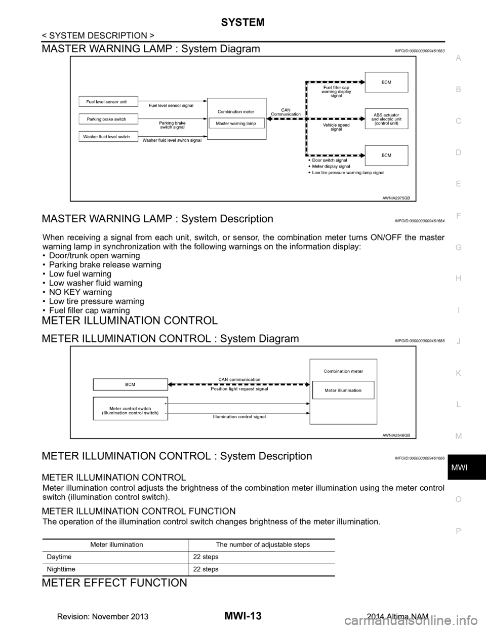
MASTER WARNING LAMP : System DiagramINFOID:0000000009461683
MASTER WARNING LAMP : System DescriptionINFOID:0000000009461684
When receiving a signal from each unit, switch, or s ensor, the combination meter turns ON/OFF the master
warning lamp in synchronization with the following warnings on the information display:
• Door/trunk open warning
• Parking brake release warning
• Low fuel warning
• Low washer fluid warning
• NO KEY warning
• Low tire pressure warning
• Fuel filler cap warning
METER ILLUMINATION CONTROL
METER ILLUMINATION CONTROL : System DiagramINFOID:0000000009461685
METER ILLUMINATION CONTROL : System DescriptionINFOID:0000000009461686
METER ILLUMINATION CONTROL
Meter illumination control adjusts the brightness of the combination meter illumination using the meter control
switch (illumination control switch).
METER ILLUMINATION CONTROL FUNCTION
The operation of the illumination control switch changes brightness of the meter illumination.
METER EFFECT FUNCTION
AWNIA2975GB
AWNIA2548GB
Meter illumination The number of adjustable steps
Daytime 22 steps
Nighttime 22 steps
Revision: November 20132014 Altima NAMRevision: November 20132014 Altima NAM