Page 2880 of 4801
TRUNK ROOM LAMP CIRCUITINL-59
< DTC/CIRCUIT DIAGNOSIS >
C
D E
F
G H
I
J
K
M A
B
INL
N
O P
Is the inspection result normal?
YES >> Check the trunk room lamp for an open. If OK, replace BCM. Refer to BCS-80, "Removal and
Installation". If NG, replace the trunk room lamp. Refer to INL-68, "Removal and Installation".
NO >> Repair or replace harness or connectors.
3.CHECK TRUNK ROOM LAMP SHORT CIRCUIT
1. Turn ignition switch OFF.
2. Disconnect BCM connector M19 and trunk room lamp connector.
3. Check continuity between BCM connector M19 terminal 85 and ground.
Is the inspection result normal?
YES >> Check the trunk room lamp for a short circuit. If OK, replace BCM. Refer to BCS-80, "Removal
and Installation". If NG, replace the trunk room lamp. Refer to INL-68, "Removal and Installation".
NO >> Repair or replace harness or connectors.
BCM
GroundContinuity
Connector Terminal
M19 85 No
Revision: November 20132014 Altima NAMRevision: November 20132014 Altima NAM
Page 2883 of 4801

INL-62
< SYMPTOM DIAGNOSIS >
INTERIOR LIGHTING SYSTEM SYMPTOMS
SYMPTOM DIAGNOSIS
INTERIOR LIGHTING SYSTEM SYMPTOMS
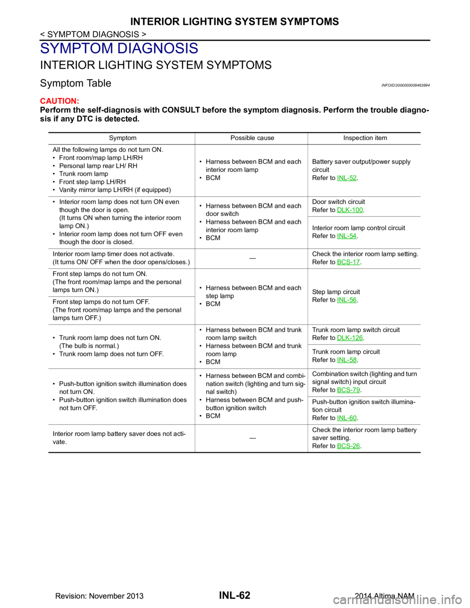
Symptom TableINFOID:0000000009463894
CAUTION:
Perform the self-diagnosis with CONSULT before th e symptom diagnosis. Perform the trouble diagno-
sis if any DTC is detected.
Symptom Possible cause Inspection item
All the following lamps do not turn ON.
• Front room/map lamp LH/RH
• Personal lamp rear LH/ RH
• Trunk room lamp
• Front step lamp LH/RH
• Vanity mirror lamp LH/RH (if equipped) • Harness between BCM and each
interior room lamp
•BCM Battery saver output/power supply
circuit
Refer to INL-52
.
• Interior room lamp does not turn ON even though the door is open.
(It turns ON when turn ing the interior room
lamp ON.)
• Interior room lamp does not turn OFF even though the door is closed. • Harness between BCM and each
door switch
• Harness between BCM and each interior room lamp
•BCM Door switch circuit
Refer to DLK-100
.
Interior room lamp control circuit
Refer to INL-54
.
Interior room lamp timer does not activate.
(It turns ON/ OFF when the door opens/closes.) —Check the interior room lamp setting.
Refer to BCS-17
.
Front step lamps do not turn ON.
(The front room/map lamps and the personal
lamps turn ON.) • Harness between BCM and each
step lamp
•BCM St ep la mp ci rcu it
Refer to INL-56
.
Front step lamps do not turn OFF.
(The front room/map lamps and the personal
lamps turn OFF.)
• Trunk room lamp does not turn ON. (The bulb is normal.)
• Trunk room lamp does not turn OFF. • Harness between BCM and trunk
room lamp switch
• Harness between BCM and trunk room lamp
•BCM Trunk room lamp switch circuit
Refer to DLK-126
.
Trunk room lamp circuit
Refer to INL-58
.
• Push-button ignition switch illumination does not turn ON.
• Push-button ignition switch illumination does not turn OFF. • Harness between BCM and combi-
nation switch (lighting and turn sig-
nal switch)
• Harness between BCM and push- button ignition switch
•BCM Combination switch (lighting and turn
signal switch) input circuit
Refer to BCS-79
.
Push-button ignition switch illumina-
tion circuit
Refer to INL-60
.
Interior room lamp battery saver does not acti-
vate. —Check the interior room lamp battery
saver setting.
Refer to BCS-26
.
Revision: November 20132014 Altima NAMRevision: November 20132014 Altima NAM
Page 2889 of 4801

INL-68
< REMOVAL AND INSTALLATION >
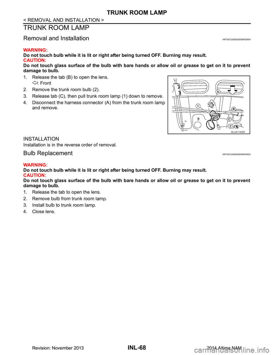
TRUNK ROOM LAMP
TRUNK ROOM LAMP
Removal and InstallationINFOID:0000000009463904
WARNING:
Do not touch bulb while it is lit or right after being turned OFF. Burning may result.
CAUTION:
Do not touch glass surface of the bulb with bare ha nds or allow oil or grease to get on it to prevent
damage to bulb.
1. Release the tab (B) to open the lens. : Front
2. Remove the trunk room bulb (2).
3. Release tab (C), then pull trunk room lamp (1) down to remove.
4. Disconnect the harness connector (A ) from the trunk room lamp
and remove.
INSTALLATION
Installation is in the reverse order of removal.
Bulb ReplacementINFOID:0000000009463905
WARNING:
Do not touch bulb while it is lit or right after being turned OFF. Burning may result.
CAUTION:
Do not touch glass surface of the bulb with bare ha nds or allow oil or grease to get on it to prevent
damage to bulb.
1. Release the tab to open the lens.
2. Remove bulb from trunk room lamp.
3. Install bulb to trunk room lamp.
4. Close lens.
ALLIA1154ZZ
Revision: November 20132014 Altima NAMRevision: November 20132014 Altima NAM
Page 2891 of 4801
INL-70
< SERVICE DATA AND SPECIFICATIONS (SDS)
SERVICE DATA AND SPECIFICATIONS (SDS)
SERVICE DATA AND SPECIFICATIONS (SDS)
SERVICE DATA AND SPECIFICATIONS (SDS)
Bulb SpecificationsINFOID:0000000009463907
* Always check with the Parts Department for the latest parts information.Item Wattage (W)*
Front room/map lamp LED
Vanity mirror lamp -
Glove box lamp -
Front step lamp 3.8
Personal lamp rear 8
Trunk room lamp 3.4
Revision: November 20132014 Altima NAMRevision: November 20132014 Altima NAM
Page 2893 of 4801

INT-2
Removal and Installation ........................................30
TRUNK ROOM TRIM & TRUNK LID FINISH-
ER ................................................................... ...
33
Exploded View ..................................................... ...33
TRUNK LID FINISHER ........................................... ...33
TRUNK LID FINISHER : Removal and Installation ...33
TRUNK FLOOR CARPET ...................................... ...33
TRUNK FLOOR CARPET : Removal and Installa-
tion ....................................................................... ...
33
TRUNK SIDE FINISHER ........................................ ...34
TRUNK SIDE FINISHER : Removal and Installa-
tion ....................................................................... ...
34
TRUNK CARGO NET ............................................. ...34
TRUNK CARGO NET : Removal and Installation ...34
TRUNK REAR FINISHER .........................................35
TRUNK REAR FINISHER : Removal and Installa-
tion ....................................................................... ...
35
Revision: November 20132014 Altima NAM
Page 2902 of 4801

SQUEAK AND RATTLE TROUBLE DIAGNOSESINT-11
< SYMPTOM DIAGNOSIS >
C
D E
F
G H
I
K L
M A
B
INT
N
O P
INSTRUMENT PANEL
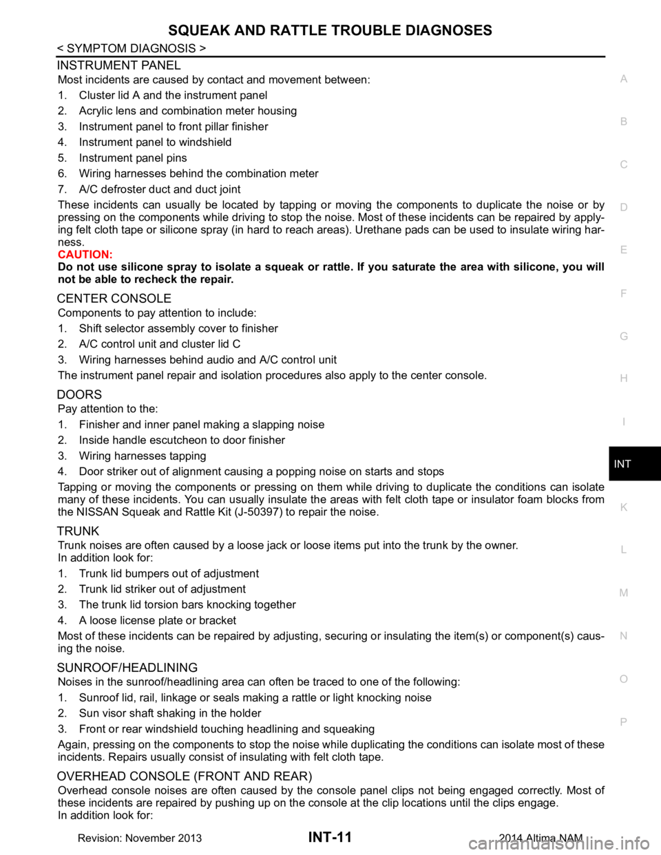
Most incidents are caused by contact and movement between:
1. Cluster lid A and the instrument panel
2. Acrylic lens and combination meter housing
3. Instrument panel to front pillar finisher
4. Instrument panel to windshield
5. Instrument panel pins
6. Wiring harnesses behind the combination meter
7. A/C defroster duct and duct joint
These incidents can usually be located by tapping or moving the components to duplicate the noise or by
pressing on the components while driving to stop the noi se. Most of these incidents can be repaired by apply-
ing felt cloth tape or silicone spray (in hard to reach areas). Urethane pads can be used to insulate wiring har-
ness.
CAUTION:
Do not use silicone spray to isolate a squeak or ra ttle. If you saturate the area with silicone, you will
not be able to recheck the repair.
CENTER CONSOLE
Components to pay attention to include:
1. Shift selector assembly cover to finisher
2. A/C control unit and cluster lid C
3. Wiring harnesses behind audio and A/C control unit
The instrument panel repair and isolation pr ocedures also apply to the center console.
DOORS
Pay attention to the:
1. Finisher and inner panel making a slapping noise
2. Inside handle escutcheon to door finisher
3. Wiring harnesses tapping
4. Door striker out of alignment causing a popping noise on starts and stops
Tapping or moving the components or pressing on them wh ile driving to duplicate the conditions can isolate
many of these incidents. You can usually insulate the ar eas with felt cloth tape or insulator foam blocks from
the NISSAN Squeak and Rattle Kit (J-50397) to repair the noise.
TRUNK
Trunk noises are often caused by a loose jack or loose items put into the trunk by the owner.
In addition look for:
1. Trunk lid bumpers out of adjustment
2. Trunk lid striker out of adjustment
3. The trunk lid torsion bars knocking together
4. A loose license plate or bracket
Most of these incidents can be repaired by adjusting, se curing or insulating the item(s) or component(s) caus-
ing the noise.
SUNROOF/HEADLINING
Noises in the sunroof/headlining area can often be traced to one of the following:
1. Sunroof lid, rail, linkage or seals making a rattle or light knocking noise
2. Sun visor shaft shaking in the holder
3. Front or rear windshield touching headlining and squeaking
Again, pressing on the components to stop the noise while duplicating the conditions can isolate most of these
incidents. Repairs usually consist of insulating with felt cloth tape.
OVERHEAD CONSOLE (FRONT AND REAR)
Overhead console noises are often caused by the cons ole panel clips not being engaged correctly. Most of
these incidents are repaired by pushing up on the c onsole at the clip locations until the clips engage.
In addition look for:
Revision: November 20132014 Altima NAM
Page 2924 of 4801
TRUNK ROOM TRIM & TRUNK LID FINISHERINT-33
< REMOVAL AND INSTALLATION >
C
D E
F
G H
I
K L
M A
B
INT
N
O P
TRUNK ROOM TRIM & TRUNK LID FINISHER
Exploded ViewINFOID:0000000009461364
TRUNK LID FINISHER
TRUNK LID FINISHER : Re moval and InstallationINFOID:0000000009461365
REMOVAL
1. Release the trunk lid finisher clips.
: Clip
2. Remove the trunk lid finisher.
INSTALLATION
Installation is in the reverse order of removal.
TRUNK FLOOR CARPET
TRUNK FLOOR CARPET : Re moval and InstallationINFOID:0000000009461366
REMOVAL
1. Remove the rear seat back. Refer to SE-36, "Removal and Installation - Seat Assembly".
1. Trunk lid finisher 2. Trunk side finisher (LH) 3. Trunk cargo net (if equipped)
4. Trunk rear finisher 5. Trunk floor carpet 6. Trunk side finisher (RH)
Front
ALJIA0915ZZ
ALJIA0919ZZ
Revision: November 20132014 Altima NAM
Page 2925 of 4801
INT-34
< REMOVAL AND INSTALLATION >
TRUNK ROOM TRIM & TRUNK LID FINISHER
2. Remove the trunk floor carpet clips.: Clip
3. Remove the trunk floor carpet.
INSTALLATION
Installation is in the reverse order of removal.
TRUNK SIDE FINISHER
TRUNK SIDE FINISHER : Removal and InstallationINFOID:0000000009461367
REMOVAL
1. Lower the rear seat back.
2. Remove the rear seat bolster. Refer to SE-38, "Removal and Installation - Rear Seat Bolster"
.
3. Remove the trunk rear finisher. Refer to INT-35, "TRUNK REAR FINISHER : Removal and Installation"
.
4. Remove the trunk side finisher clips. : Clip
5. Remove the trunk side finisher.
INSTALLATION
Installation is in the reverse order of removal.
TRUNK CARGO NET
TRUNK CARGO NET : Remo val and InstallationINFOID:0000000009461368
REMOVAL
1. Unclip the trunk cargo net from the trunk cargo net fasteners (A).
2. Remove the trunk cargo net.
ALJIA0920ZZ
ALJIA0918ZZ
ALJIA0917ZZ
Revision: November 20132014 Altima NAM