2014 NISSAN TEANA trunk
[x] Cancel search: trunkPage 3270 of 4801

MWI
SYSTEMMWI-15
< SYSTEM DESCRIPTION >
C
D E
F
G H
I
J
K L
M B
A
O P
Engine-start effect exits when any of the above operat ional conditions is cancelled during the engine-start
effect.
INFORMATION DISPLAY
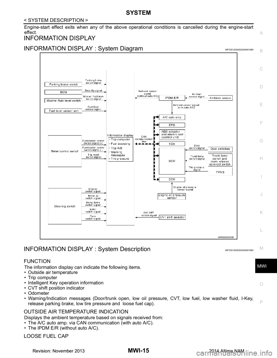
INFORMATION DISPLAY : System DiagramINFOID:0000000009461689
INFORMATION DISPLAY : System DescriptionINFOID:0000000009461690
FUNCTION
The information display can indicate the following items.
• Outside air temperature
• Trip computer
• Intelligent Key operation information
• CVT shift position indicator
• Odometer
• Warning/Indication messages (Door/trunk open, low oil pressure, CVT, low fuel, low washer fluid, I-Key,
release parking brake, low tire pressure and loose fuel cap).
OUTSIDE AIR TEMPERATURE INDICATION
Displays the ambient temperature based on signals received from:
• The A/C auto amp. via CAN communication (with auto A/C).
• The IPDM E/R (without auto A/C).
LOOSE FUEL CAP
AWNIA2645GB
Revision: November 20132014 Altima NAMRevision: November 20132014 Altima NAM
Page 3271 of 4801

MWI-16
< SYSTEM DESCRIPTION >
SYSTEM
The LOOSE FUEL CAP message will display in the information display when the fuel-filler cap is not tightened
correctly. The message will turn off as soon as the EC M detects the fuel-filler cap is properly tightened. The
ECM provides a loose fuel cap signal to the combination meter via CAN communication.
LOW TIRE PRESSURE WARNING
This warning appears when the BCM detects low inflati on pressure or a system malfunction. The BCM sends
a signal to the combination meter via CAN communication to illuminate the low tire pressure warning lamp. In
addition, a warning message will be displayed in the vehicle information display.
DOOR OPEN WARNING
This warning appears when the ignition switch is ON and the door is open. The BCM receives a door switch
signal from the door open door switch. The BCM sends t he door switch signal to the combination meter via
CAN communication lines.
TRUNK OPEN WARNING
This warning appears when the ignition switch is ON and the trunk is opened. The BCM receives a trunk lamp
switch signal from the trunk lamp switch. The BCM s ends the trunk lamp switch signal to the combination
meter via CAN communication.
LOW FUEL WARNING
This warning appears when the fuel level in the fuel tank is less than approximately 4 US gal (15 L, 3.3 Imp
gal). A variable resistor signal is supplied to the combi nation meter from the fuel level sensor unit to determine
the amount of fuel in the fuel tank.
LOW WINDSHIELD WASHER FLUID WARNING
When the windshield washer fluid level is low, the was her fluid level switch provides a ground signal to the
combination meter and the warning is displayed. Once fluid is added, the switch opens and the warning is no
longer displayed.
RELEASE PARKING BRAKE WARNING
When the parking brake is applied, the parking brake switch provides a ground signal to the combination
meter. When the vehicle speed is greater than 4 MPH (7 km/h), the message is displayed and the warning
chime sounds.
SHIFT POSITION INDICATOR
Displays the position of the shift selector based on signals received from TCM via CAN communication.
LOW OIL PRESSURE WARNING
The low oil pressure warning appears in the information display when the combination meter receives a low
engine oil pressure signal from the ECM via CAN communication.
WARNING CHECK INDICATION
The combination meter can cause an interrupt on the information display to indicate a warning, based on sig-
nals received from each unit and switch.
Refer to Owner’s Manual for additional information display items.
COMPASS
COMPASS : DescriptionINFOID:0000000009461691
DESCRIPTION
With the ignition switch in the ON position, and the mode (N) switch
ON, the compass display will indicate the direction the vehicle is
heading.
Vehicle direction is displayed as follows:
• N: north
• E: east
• S: south
•W: west
LKIA0447E
Revision: November 20132014 Altima NAMRevision: November 20132014 Altima NAM
Page 3274 of 4801
![NISSAN TEANA 2014 Service Manual
MWI
DIAGNOSIS SYSTEM (METER)MWI-19
< SYSTEM DESCRIPTION >
C
D E
F
G H
I
J
K L
M B
A
O P
Refer to MWI-27, "DTC Index".
DATA MONITOR
Display Item List
X: Applicable
Display item [Unit] MAIN
SIGNALS NISSAN TEANA 2014 Service Manual
MWI
DIAGNOSIS SYSTEM (METER)MWI-19
< SYSTEM DESCRIPTION >
C
D E
F
G H
I
J
K L
M B
A
O P
Refer to MWI-27, "DTC Index".
DATA MONITOR
Display Item List
X: Applicable
Display item [Unit] MAIN
SIGNALS](/manual-img/5/57390/w960_57390-3273.png)
MWI
DIAGNOSIS SYSTEM (METER)MWI-19
< SYSTEM DESCRIPTION >
C
D E
F
G H
I
J
K L
M B
A
O P
Refer to MWI-27, "DTC Index".
DATA MONITOR
Display Item List
X: Applicable
Display item [Unit] MAIN
SIGNALS Description
SPEED METER
[mph or km/h] X Displays the value of vehicle speed signal.
SPEED OUTPUT
[mph or km/h] X Vehicle speed signal value transmitted to other units via CAN communication.
ODO OUTPUT
[mph or km/h] Odometer signal value transmitted to other units via CAN communication.
TACHO METER
[rpm] X Value of the engine speed signal received from ECM via CAN communication.
FUEL METER
[L] X Fuel level indicated on combination meter.
W TEMP METER
[ ° F] or [ °C] X Displays the value of engine coolant temperature signal, which is input from ECM.
ABS W/L
[On/Off] Displays [ON/OFF] condition of ABS warning indicator.
VDC/TCS IND
[ON/OFF] Displays [ON/OFF] condition of VDC OFF indicator lamp.
SLIP IND
[ON/OFF] Displays [ON/OFF] condition of SLIP indicator lamp.
BRAKE W/L
[ON/OFF] Displays [ON/OFF] condition of brake warning indicator.
DOOR W/L
[ON/OFF] Displays [ON/OFF] condition of door warning message.
TRUNK/GLAS-H
[On/Off] Displays [ON/OFF] condition of trunk warning message.
HI-BEAM IND
[ON/OFF] Displays [ON/OFF] condition of high beam indicator.
TURN IND
[On/Off] Displays [ON/OFF] condition of turn indicator.
FR FOG IND
[On/Off] Displays [ON/OFF] condition of front fog lamp indicator.
LIGHT IND
[On/Off] Displays [ON/OFF] condition of light indicator.
OIL W/L
[ON/OFF] Displays [ON/OFF] condition of low oil pressure warning message.
MIL
[ON/OFF] Displays [ON/OFF] condition of malfunction indicator.
CRUISE IND
[Off] Displays [ON/OFF] condition of CRUISE
indicator in the information display.
CRUISE W/L
[ON/OFF] Displays [ON/OFF] condition of
tire CRUISE warning message.
CVT IND
[Off] Displays [ON/OFF] condition of CVT indicator in the information display.
SET IND
[On/Off] Displays [ON/OFF] condition of SET indicator in the information display.
O/D OFF IND
[ON/OFF] Displays [ON/OFF] condition of O/D OFF indicator.
Revision: November 20132014 Altima NAMRevision: November 20132014 Altima NAM
Page 3277 of 4801

MWI-22
< ECU DIAGNOSIS INFORMATION >
COMBINATION METER
ECU DIAGNOSIS INFORMATION
COMBINATION METER
Reference ValueINFOID:0000000009461694
VALUES ON THE DIAGNOSIS TOOL
Monitor Item Condition Value/Status
SPEED METER
[mph or km/h] Ignition switch ON While driving
Input value of vehicle speed signal
(CAN communication signal)
SPEED OUTPUT
[mph or km/h] Ignition switch ON While driving Output value of vehicle speed sig-
nal (CAN communication signal)
ODO OUTPUT
[mph or km/h] Ignition switch ON — Output value of odometer signal
(CAN communication signal)
TACHO METER
[rpm] Ignition switch ON Engine running
Input value of engine speed signal
(CAN communication signal)
FUEL METER
[L] Ignition switch ON — Input value of fuel level sensor sig-
nal
W TEMP METER
[ ° F] or [ °C] Ignition switch ON — Input value of engine coolant tem-
perature signal (CAN communica-
tion signal)
ABS W/L Ignition switch ON ABS warning lamp ON On
ABS warning lamp OFF Off
VDC/TCS IND Ignition switch ON VDC OFF indica
tor lamp ON On
VDC OFF indicato r lamp OFF Off
SLIP IND Ignition switch ON VDC warning lamp ON On
VDC warning lamp OFF Off
BRAKE W/L Ignition switch ON Brake warning lamp ON On
Brake warning lamp OFF Off
DOOR W/L Ignition switch ON Door open warning ON On
Other than the above Off
TRUNK/GLAS-H Ignition switch ON Trunk open warning ON On
Trunk open warning OFF Off
HI-BEAM IND Ignition switch ON High beam indicator lamp ON On
High beam indicator lamp OFF Off
TURN IND Ignition switch ON Turn signal indicator lamp ON On
Turn signal indicator lamp OFF Off
LIGHT IND Ignition switch ON Tail lamp indicator lamp ON On
Tail lamp indicator lamp OFF Off
FR FOG IND Ignition switch ON Front fog lamp indicator lamp ON On
Front fog lamp indicator lamp OFF Off
OIL W/L Ignition switch ON Oil pressure warning On
Oil pressure warning Off
MIL Ignition switch ON Malfunction indicator lamp ON On
Malfunction indicator lamp OFF Off
CRUISE IND Ignition switch ON CRUISE indicator ON On
CRUISE indicator OFF Off
Revision: November 20132014 Altima NAMRevision: November 20132014 Altima NAM
Page 3332 of 4801

MWI
THE DOOR OPEN WARNING CONTINUES DISPLAYING, OR DOES NOT DIS-
PLAY
MWI-77
< SYMPTOM DIAGNOSIS >
C
D E
F
G H
I
J
K L
M B
A
O P
THE DOOR OPEN WARN ING CONTINUES DISPLAYING, OR DOES NOT
DISPLAY
DescriptionINFOID:0000000009461748
• The door ajar warning is displayed even though all of the doors and the trunk are closed.
• The door ajar warning is not displayed even though a door or the trunk is ajar.
Diagnosis ProcedureINFOID:0000000009461749
1.CHECK BCM INPUT SIGNAL
Check the BCM input signal. Refer to DLK-100, "Component Function Check"
.
Is the inspection result normal?
YES >> GO TO 2.
NO >> GO TO 3.
2.CHECK COMBINATION METER INPUT SIGNAL
Select the METER/M&A Data Monitor and check t he DOOR W/L monitor value while opening and closing
doors.
Is the inspection result normal?
YES >> Replace combination meter. Refer to MWI-82, "Removal and Installation".
NO >> Replace BCM. Refer to BCS-80, "Removal and Installation"
.
3.CHECK DOOR SWITCH SIGNAL CIRCUIT
Check the door switch signal circuit. Refer to DLK-100, "Diagnosis Procedure"
.
Is the inspection result normal?
YES >> GO TO 4.
NO >> Repair or replace harness or connectors.
4.CHECK DOOR SWITCH
Perform a unit check for the door switch. Refer to DLK-102, "Component Inspection"
.
Is the inspection result normal?
YES >> Replace combination meter. Refer to MWI-82, "Removal and Installation".
NO >> Replace applicable door switch. Refer to DLK-219, "Removal and Installation"
.
DOOR W/L
Door open : On
Door closed : Off
Revision: November 20132014 Altima NAMRevision: November 20132014 Altima NAM
Page 3333 of 4801

MWI-78
< SYMPTOM DIAGNOSIS >
THE TRUNK OPEN WARNING CONTINUES DISPLAYING, OR DOES NOT DIS-
PLAY
THE TRUNK OPEN WARNING CONTIN UES DISPLAYING, OR DOES NOT
DISPLAY
DescriptionINFOID:0000000009461750
• The trunk ajar warning is displayed continuously even though the trunk lid is closed.
• The trunk ajar warning is not displayed even though the trunk lid is open.
Diagnosis ProcedureINFOID:0000000009461751
1.CHECK BCM INPUT SIGNAL
1. Connect the CONSULT.
2. Check the BCM input signals. Refer to DLK-126, "Component Function Check"
.
Is the inspection result normal?
YES >> GO TO 2.
NO >> GO TO 3.
2.CHECK COMBINATION METER INPUT SIGNAL
Select the Data Monitor for the METER/M &A and check the TRUNK/GLAS-H monitor value.
Is the inspection result normal?
YES >> Replace combination meter. Refer to MWI-82, "Removal and Installation".
NO >> Replace BCM. Refer to BCS-80, "Removal and Installation"
.
3.CHECK TRUNK ROOM LAMP SWITCH SIGNAL CIRCUIT
Check the trunk room lamp switch signal circuit. Refer to DLK-126, "Diagnosis Procedure"
.
Is the inspection result normal?
YES >> GO TO 4.
NO >> Repair harness or connector.
4.CHECK TRUNK ROOM LAMP SWITCH
Check the room lamp switch. Refer to DLK-127, "Component Inspection"
.
Is the inspection result normal?
YES >> Replace combination meter. Refer to MWI-82, "Removal and Installation".
NO >> Replace trunk lid lock assembly. Refer to DLK-210, "TRUNK LAMP SWITCH AND TRUNK
RELEASE SOLENOID : Removal and Installation".
TRUNK/GLAS-H
Trunk lid open : On
Trunk lid closed : Off
Revision: November 20132014 Altima NAMRevision: November 20132014 Altima NAM
Page 3387 of 4801
![NISSAN TEANA 2014 Service Manual
PCS-38
< SYSTEM DESCRIPTION >[POWER DISTRIBUTION SYSTEM]
DIAGNOSIS SYSTEM (BCM)
DIAGNOSIS SYSTEM (BCM)
COMMON ITEM
COMMON ITEM : CONSULT Fu
nction (BCM - COMMON ITEM)INFOID:0000000009941330
CAUTION: NISSAN TEANA 2014 Service Manual
PCS-38
< SYSTEM DESCRIPTION >[POWER DISTRIBUTION SYSTEM]
DIAGNOSIS SYSTEM (BCM)
DIAGNOSIS SYSTEM (BCM)
COMMON ITEM
COMMON ITEM : CONSULT Fu
nction (BCM - COMMON ITEM)INFOID:0000000009941330
CAUTION:](/manual-img/5/57390/w960_57390-3386.png)
PCS-38
< SYSTEM DESCRIPTION >[POWER DISTRIBUTION SYSTEM]
DIAGNOSIS SYSTEM (BCM)
DIAGNOSIS SYSTEM (BCM)
COMMON ITEM
COMMON ITEM : CONSULT Fu
nction (BCM - COMMON ITEM)INFOID:0000000009941330
CAUTION:
After disconnecting the CONSULT vehicle interface (VI) from the data link connector, the ignition must
be cycled OFF → ON (for at least 5 seconds) → OFF. If this step is not performed, the BCM may not go
to ”sleep mode”, potentially causing a di scharged battery and a no-start condition.
APPLICATION ITEM
CONSULT performs the following functions via CAN communication with BCM.
SYSTEM APPLICATION
BCM can perform the following functions.
Direct Diagnostic Mode Description
Ecu Identification The BCM part number is displayed.
Self Diagnostic Result The BCM self diagnostic results are displayed.
Data Monitor The BCM input/output data is displayed in real time.
Active Test The BCM activates outputs to test components.
Work support The settings for BCM functions can be changed.
Configuration • The vehicle specification can be read and saved.
• The vehicle specification can be written when replacing BCM.
CAN Diag Support Mntr The result of transmit/receive diagnosis of CAN communication is displayed.
System Sub System Direct Diagnostic Mode
Ecu Identification
Self Diagnostic Result
Data Monitor
Active Test
Work support
Configuration
CAN Diag Su pport Mntr
Door lock DOOR LOCK ××××
Rear window defogger REAR DEFOGGER ×××
Warning chime BUZZER ××
Interior room lamp timer INT LAMP ×××
Remote keyless entry system MULTI REMOTE ENT ×××
Exterior lamp HEADLAMP ×××
Wiper and washer WIPER ×××
Turn signal and hazard warning lamps FLASHER ××
Air conditioner AIR CONDITIONER ×
Intelligent Key system INTELLIGENT KEY ××××
Combination switch COMB SW ×
BCM BCM × × ×××
Immobilizer IMMU ×××
Interior room lamp battery saver BATTERY SAVER ××
Trunk open TRUNK ×
Vehicle security system THEFT ALM ×××
Revision: November 20132014 Altima NAMRevision: November 20132014 Altima NAM
Page 3388 of 4801
![NISSAN TEANA 2014 Service Manual
PCS
DIAGNOSIS SYSTEM (BCM)PCS-39
< SYSTEM DESCRIPTION > [POWER DISTRIBUTION SYSTEM]
C
D E
F
G H
I
J
K L
B
A
O P
N
INTELLIGENT KEY
INTELLIGENT KEY : CONSULT Func
tion (BCM - INTELLIGENT KEY)INFOID:0 NISSAN TEANA 2014 Service Manual
PCS
DIAGNOSIS SYSTEM (BCM)PCS-39
< SYSTEM DESCRIPTION > [POWER DISTRIBUTION SYSTEM]
C
D E
F
G H
I
J
K L
B
A
O P
N
INTELLIGENT KEY
INTELLIGENT KEY : CONSULT Func
tion (BCM - INTELLIGENT KEY)INFOID:0](/manual-img/5/57390/w960_57390-3387.png)
PCS
DIAGNOSIS SYSTEM (BCM)PCS-39
< SYSTEM DESCRIPTION > [POWER DISTRIBUTION SYSTEM]
C
D E
F
G H
I
J
K L
B
A
O P
N
INTELLIGENT KEY
INTELLIGENT KEY : CONSULT Func
tion (BCM - INTELLIGENT KEY)INFOID:0000000009941331
CAUTION:
After disconnecting the CONSULT vehicle interface (VI) from the data link connector, the ignition must
be cycled OFF → ON (for at least 5 seconds) → OFF. If this step is not performed, the BCM may not go
to ”sleep mode”, potentiall y causing a discharged battery and a no-start condition.
SELF DIAGNOSTIC RESULT
Refer to BCS-52, "DTC Index".
DATA MONITOR
RAP system RETAINED PWR ×
Signal buffer system SIGNAL BUFFER ×
TPMS AIR PRESSURE MONITOR ××××
System Sub System
Direct Diagnostic Mode
Ecu Identification
Self Diagnostic Result
Data Monitor
Active Test
Work support
Configuration
CAN Diag Support Mntr
Monitor Item [Unit] Main Description
REQ SW -DR [On/Off] ×Indicates condition of door request switch LH.
REQ SW -AS [On/Off] ×Indicates condition of door request switch RH.
REQ SW -BD/TR [On/Off] ×Indicates condition of trunk opener request switch.
PUSH SW [On/Off] Indicates condition of push-button ignition switch.
SHFTLCK SLNID PER SPLY [On/Off] ×Indicates condition of power supply to shiftlock solenoid.
BRAKE SW 1 [On/Off] ×Indicates condition of brake switch.
BRAKE SW 2 [On/Off] Indicates condition of brake switch.
DETE/CANCL SW [On/Off] ×Indicates condition of P (park) position.
SFT PN/N SW [On/Off] ×Indicates condition of P (park) or N (neutral) position.
UNLK SEN -DR [On/Off] ×Indicates condition of door unlock sensor.
PUSH SW -IPDM [On/Off] Indicates condition of push-button ignition switch received from IPDM E/R
on CAN communication line.
IGN RLY1 -F/B [On/Off] Indicates condition of ignition relay 1 received from IPDM E/R on CAN
communication line.
DETE SW -IPDM [On/Off] Indicates condition of detent switch received from TCM on CAN communi-
cation line.
SFT PN -IPDM [On/Off] Indicates condition of P (park) or N (neutral) position from TCM on CAN
communication line.
SFT P -MET [On/Off] Indicates condition of P (park) position from TCM on CAN communication
line.
SFT N -MET [On/Off] Indicates condition of N (neutral) position from IPDM E/R on CAN commu-
nication line.
ENGINE STATE [STOP/START/CRANK/RUN] ×Indicates condition of engine state from ECM on CAN communication line.
VEH SPEED 1 [mph/km/h] ×Indicates condition of vehicle speed signal received from ABS on CAN
communication line.
Revision: November 20132014 Altima NAMRevision: November 20132014 Altima NAM