Page 979 of 4801

TRUNK LIDDLK-211
< REMOVAL AND INSTALLATION >
C
D E
F
G H
I
J
L
M A
B
DLK
N
O P
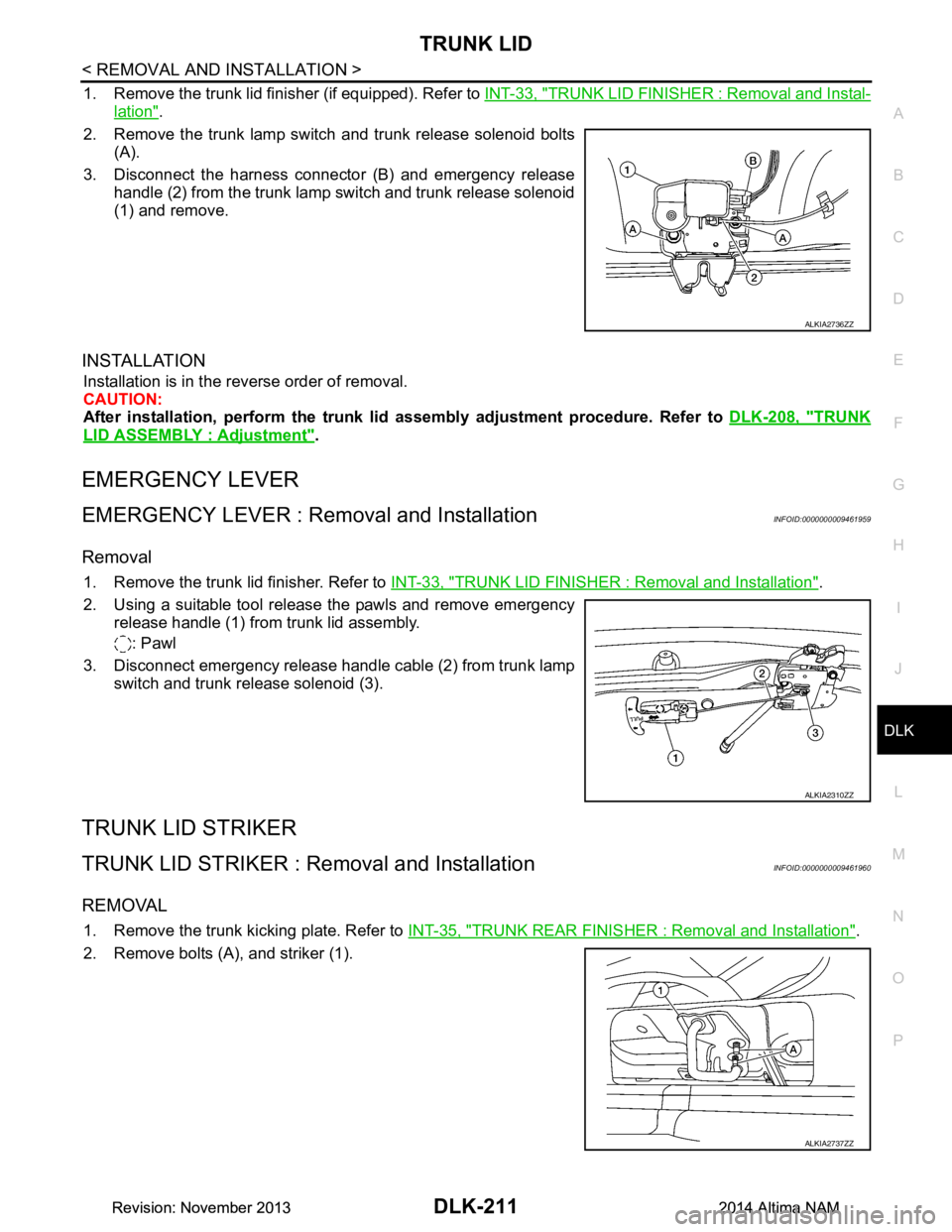
1. Remove the trunk lid finisher (if equipped). Refer to INT-33, "TRUNK LID FINISHER : Removal and Instal-
lation".
2. Remove the trunk lamp switch and trunk release solenoid bolts (A).
3. Disconnect the harness connector (B) and emergency release handle (2) from the trunk lamp switch and trunk release solenoid
(1) and remove.
INSTALLATION
Installation is in the reverse order of removal.
CAUTION:
After installation, perform the trunk lid assembly adjustment procedure. Refer to DLK-208, "TRUNK
LID ASSEMBLY : Adjustment".
EMERGENCY LEVER
EMERGENCY LEVER : Removal and InstallationINFOID:0000000009461959
Removal
1. Remove the trunk lid finisher. Refer to INT-33, "TRUNK LID FINISHER : Removal and Installation".
2. Using a suitable tool release the pawls and remove emergency release handle (1) from trunk lid assembly.
: Pawl
3. Disconnect emergency release handle cable (2) from trunk lamp switch and trunk release solenoid (3).
TRUNK LID STRIKER
TRUNK LID STRIKER : Re moval and InstallationINFOID:0000000009461960
REMOVAL
1. Remove the trunk kicking plate. Refer to INT-35, "TRUNK REAR FINISHER : Removal and Installation".
2. Remove bolts (A), and striker (1).
ALKIA2736ZZ
ALKIA2310ZZ
ALKIA2737ZZ
Revision: November 20132014 Altima NAMRevision: November 20132014 Altima NAM
Page 980 of 4801
DLK-212
< REMOVAL AND INSTALLATION >
TRUNK LID
INSTALLATION
Installation is in the reverse order of removal.
CAUTION:
After installation, perform the trunk lid assembly adjustment procedure. Refer to DLK-208, "TRUNK
LID ASSEMBLY : Adjustment".
Revision: November 20132014 Altima NAMRevision: November 20132014 Altima NAM
Page 983 of 4801

FUEL FILLER LID OPENERDLK-215
< REMOVAL AND INSTALLATION >
C
D E
F
G H
I
J
L
M A
B
DLK
N
O P
6. Remove trunk side finisher (LH). Refer to INT-34, "TRUNK SIDE FINISHER : Removal and Installation".
7. Remove fuel filler lid opener cable from fuel filler lid lock assembly. Refer to DLK-215, "FUEL FILLER LID
LOCK : Removal and Installation".
8. Disengage each harness protector (1), and then remove fuel filler lid opener cable (2).
INSTALLATION
Installation is in the reverse order of removal.
CAUTION:
After installation, check fuel filler li d assembly open/close, lock/unlock operation.
FUEL FILLER LID LOCK
FUEL FILLER LID LOCK : Removal and InstallationINFOID:0000000009461964
REMOVAL
1. Fully open fuel filler lid.
2. Insert a suitable tool (A) as shown into bottom of fuel filler lock assembly(1).
3. Release lower pawls (A) using a suitable tool and remove fuel filler lid lock assembly (1) from opening.
CAUTION:
Be careful not to damage gasket (2) when removing.
JMKIA5720ZZ
ALKIA2731ZZ
JMKIA8138ZZ
Revision: November 20132014 Altima NAMRevision: November 20132014 Altima NAM
Page 994 of 4801
DLK-226
< REMOVAL AND INSTALLATION >
TRUNK LID OPENER CANCEL SWITCH
TRUNK LID OPENER CANCEL SWITCH
Removal and InstallationINFOID:0000000009461978
REMOVAL
1. Remove the glove box assembly. Refer to IP-22, "Removal and Installation".
2. Release pawls and remove the trunk cancel switch.
INSTALLATION
Installation is in the reverse order of removal.
Revision: November 20132014 Altima NAMRevision: November 20132014 Altima NAM
Page 995 of 4801
TRUNK LID OPENER SWITCHDLK-227
< REMOVAL AND INSTALLATION >
C
D E
F
G H
I
J
L
M A
B
DLK
N
O P
TRUNK LID OPENER SWITCH
Removal and InstallationINFOID:0000000009461979
REMOVAL
1. Remove the instrument lower panel LH. Refer to IP-21, "Removal and Installation".
2. Remove screws (A) that retain the upper switch carrier (1) to the instrument lower panel LH (2).
3. Release upper tab (B) and lower tab (C) using a suitable tool (A), then remove the trunk open switch (1) from the upper switch
carrier.
(1) Trunk opener switch
(2) VDC switch
(3) Heated steering wheel switch (if equipped)
(4) Blank
INSTALLATION
Installation is in the reverse order of removal.
ALKIA2729ZZ
ALOIA0144ZZ
Revision: November 20132014 Altima NAMRevision: November 20132014 Altima NAM
Page 996 of 4801
DLK-228
< REMOVAL AND INSTALLATION >
TRUNK OPENER REQUEST SWITCH
TRUNK OPENER REQUEST SWITCH
Removal and InstallationINFOID:0000000009461980
REMOVAL
1. Remove the license plate lamp finisher. Refer to EXT-37, "Removal and Installation".
2. Release the pawls and remove the trunk opener request switch (1).
: Pawl
INSTALLATION
Installation is in the reverse order of removal.
ALKIA2722ZZ
Revision: November 20132014 Altima NAMRevision: November 20132014 Altima NAM
Page 2283 of 4801

DIAGNOSIS SYSTEM (BCM)EXL-17
< SYSTEM DESCRIPTION >
C
D E
F
G H
I
J
K
M A
B
EXL
N
O P
DIAGNOSIS SYSTEM (BCM)
COMMON ITEM
COMMON ITEM : CONSULT Function (BCM - COMMON ITEM)INFOID:0000000009956424
CAUTION:
After disconnecting the CONSULT vehicle interface (VI) from the data link connector, the ignition must
be cycled OFF → ON (for at least 5 seconds) → OFF. If this step is not performed, the BCM may not go
to ”sleep mode”, potentiall y causing a discharged battery and a no-start condition.
APPLICATION ITEM
CONSULT performs the following functions via CAN communication with BCM.
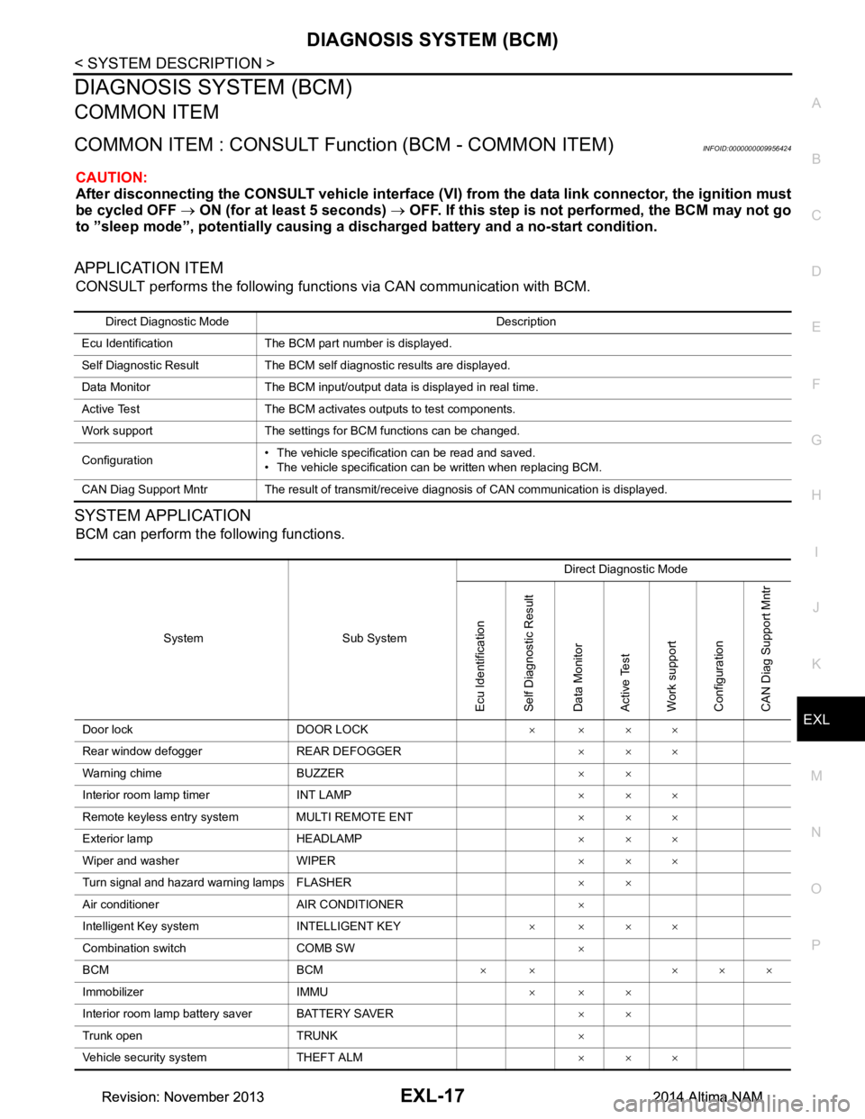
SYSTEM APPLICATION
BCM can perform the following functions.
Direct Diagnostic Mode Description
Ecu Identification The BCM part number is displayed.
Self Diagnostic Result The BCM self diagnostic results are displayed.
Data Monitor The BCM input/output data is displayed in real time.
Active Test The BCM activates outputs to test components.
Work support The settings for BCM functions can be changed.
Configuration • The vehicle specification can be read and saved.
• The vehicle specification can be written when replacing BCM.
CAN Diag Support Mntr The result of transmit/receive diagnosis of CAN communication is displayed.
System Sub System Direct Diagnostic Mode
Ecu Identification
Self Diagnostic Result
Data Monitor
Active Test
Work support
Configuration
CAN Diag Su pport Mntr
Door lock DOOR LOCK ××××
Rear window defogger REAR DEFOGGER ×××
Warning chime BUZZER ××
Interior room lamp timer INT LAMP ×××
Remote keyless entry system MULTI REMOTE ENT ×××
Exterior lamp HEADLAMP ×××
Wiper and washer WIPER ×××
Turn signal and hazard warning lamps FLASHER ××
Air conditioner AIR CONDITIONER ×
Intelligent Key system INTELLIGENT KEY ××××
Combination switch COMB SW ×
BCM BCM × × ×××
Immobilizer IMMU ×××
Interior room lamp battery saver BATTERY SAVER ××
Trunk open TRUNK ×
Vehicle security system THEFT ALM ×××
Revision: November 20132014 Altima NAMRevision: November 20132014 Altima NAM
Page 2284 of 4801

EXL-18
< SYSTEM DESCRIPTION >
DIAGNOSIS SYSTEM (BCM)
HEADLAMP
HEADLAMP : CONSULT Function (BCM - HEADLAMP)INFOID:0000000009956425
CAUTION:
After disconnecting the CONSULT vehicle interface (VI) from the data link connector, the ignition must
be cycled OFF → ON (for at least 5 seconds) → OFF. If this step is not performed, the BCM may not go
to ”sleep mode”, potentially causing a di scharged battery and a no-start condition.
DATA MONITOR
ACTIVE TEST
RAP system RETAINED PWR ×
Signal buffer system SIGNAL BUFFER ×
TPMS AIR PRESSURE MONITOR ××××
System Sub System
Direct Diagnostic Mode
Ecu Identification
Self Diagnostic Result
Data Monitor
Active Test
Work support
Configuration
CAN Diag Support Mntr
Monitor Item [Unit] Description
PUSH SW [On/Off] Indicates condition of push-button ignition switch.
ENGINE STATE [STOP/STALL/CRANK/RUN] Indicates engine st atus received from ECM on CAN communication line.
VEH SPEED 1 [km/h] Indicates vehicle speed signal received from ABS on CAN communication line.
TURN SIGNAL R [On/Off]
Indicates condition of combination switch.
TURN SIGNAL L [On/Off]
TAIL LAMP SW [On/Off]
HI BEAM SW [On/Off]
HEAD LAMP SW 1 [On/Off]
HEAD LAMP SW 2 [On/Off]
PASSING SW [On/Off]
AUTO LIGHT SW [On/Off]
FR FOG SW [On/Off]
DOOR SW-DR [On/Off] Indicates condition of front door switch LH.
DOOR SW-AS [On/Off] Indicates condition of front door switch RH.
DOOR SW-RR [On/Off] Indicates condition of rear door switch RH.
DOOR SW-RL [On/Off] Indicates condition of rear door switch LH.
DOOR SW-BK [On/Off] Indicates condition of trunk switch.
OPTI SEN (DTCT) [V] Indicates outside brightness voltage signal from optical sensor.
OPTI SEN (FILT) [V] Indicates outside brightness voltage signal from optical sensor filtered by BCM.
Test Item Description
FR FOG LAMP This test is able to check front fog lamp operation [On/Off].
DAYTIME RUNNING LIGHT This test is able to check daytime running la mp operation [On/Off].
ILL DIM SIGNAL This test is able to check head lamp illumination dimming operation [On/Off].
Revision: November 20132014 Altima NAMRevision: November 20132014 Altima NAM