2014 NISSAN TEANA fuse
[x] Cancel search: fusePage 2539 of 4801
HOW TO READ WIRING DIAGRAMSGI-11
< HOW TO USE THIS MANUAL >
C
D E
F
G H
I
J
K L
M B
GI
N
O P
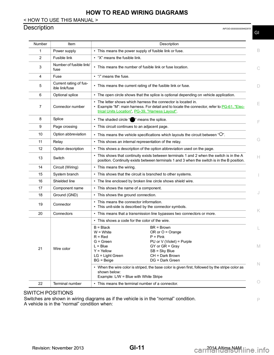
DescriptionINFOID:0000000009462978
SWITCH POSITIONS
Switches are shown in wiring diagrams as if the vehicle is in the “normal” condition.
A vehicle is in the “normal” condition when:
Number Item Description
1 Power supply • This means the power supply of fusible link or fuse.
2 Fusible link • “X” means the fusible link.
3 Number of fusible link/
fuse • This means the number of fusible link or fuse location.
4 Fuse • “/” means the fuse.
5 Current rating of fus-
ible link/fuse • This means the current rating of the fusible link or fuse.
6 Optional splice • The open circle shows that the splice is optional depending on vehicle application.
7 Connector number • The letter shows which harness the connector is located in.
• Example “M”: main harness. For detail and to locate the connector, refer to PG-61, "Elec-
trical Units Location", PG-39, "Harness Layout".
8Splice • The shaded circle “ ” means the splice.
9 Page crossing • This circuit continues to an adjacent page.
10 Option abbreviation • This means the vehicle specifications which layouts the circuit between “ ”.
11 Relay • This shows an internal representation of the relay.
12 Option description • This shows a description of the option abbreviation used on the page.
13 Switch • This shows that continuity exists between terminals 1 and 2 when the switch is in the A
position. Continuity exists between terminals 1 and 3 when the switch is in the B position.
14 Circuit (Wiring) • This means the wiring.
15 System branch • This shows that the circuit is branched to other systems.
16 Shielded line • The line enclosed by broken line circle shows shield wire.
17 Component name • This shows the name of a component.
18 Ground (GND) • This shows the ground connection.
19 Connector • This means the connector information.
• This unit-side is described by the connector symbols.
20 Connectors • This means that a transmission line bypasses two connectors or more.
21 Wire color • This shows a code for the color of the wire.
B = Black
W = White
R = Red
G = Green
L = Blue
Y = Yellow
LG = Light Green
BG = Beige BR = Brown
OR or O = Orange
P = Pink
PU or V (Violet) = Purple
GY or GR = Gray
SB = Sky Blue
CH = Dark Brown
DG = Dark Green
• When the wire color is striped, the base color is given first, followed by the stripe color as shown below:
Example: L/W = Blue with White Stripe
22 Terminal number • This means the terminal number of a connector.
Revision: November 20132014 Altima NAMRevision: November 20132014 Altima NAM
Page 2554 of 4801
GI-26
< PRECAUTION >
PRECAUTIONS
PRECAUTION
PRECAUTIONS
DescriptionINFOID:0000000009462991
Observe the following precautions to ensure safe and proper servicing. These precautions are not
described in each individual section.
Precaution for Supplemental Restraint Syst em (SRS) "AIR BAG" and "SEAT BELT
PRE-TENSIONER"
INFOID:0000000009462992
The Supplemental Restraint System such as “A IR BAG” and “SEAT BELT PRE-TENSIONER”, used along
with a front seat belt, helps to reduce the risk or severi ty of injury to the driver and front passenger for certain
types of collision. Information necessary to service the system safely is included in the SR and SB section of
this Service Manual.
WARNING:
• To avoid rendering the SRS inopera tive, which could increase the risk of personal injury or death in
the event of a collision which would result in air bag inflation, all maintenance must be performed by
an authorized NISS AN/INFINITI dealer.
• Improper maintenance, including in correct removal and installation of the SRS, can lead to personal
injury caused by unintent ional activation of the system. For re moval of Spiral Cable and Air Bag
Module, see the SR section.
• Do not use electrical test equipmen t on any circuit related to the SRS unless instructed to in this
Service Manual. SRS wiring harn esses can be identified by yellow and/or orange harnesses or har-
ness connectors.
PRECAUTIONS WHEN USING POWER TOOLS (AIR OR ELECTRIC) AND HAMMERS
WARNING:
• When working near the Airbag Diagnosis Sensor Unit or other Airbag System sensors with the Igni-
tion ON or engine running, DO NOT use air or electri c power tools or strike near the sensor(s) with a
hammer. Heavy vibration could activate the sensor( s) and deploy the air bag(s), possibly causing
serious injury.
• When using air or electric power tools or hammers , always switch the Ignition OFF, disconnect the
battery and wait at least 3 minutes before performing any service.
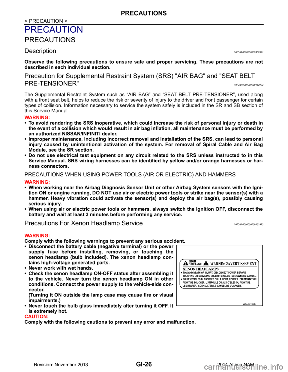
Precautions For Xeno n Headlamp ServiceINFOID:0000000009462993
WARNING:
Comply with the following warnings to prevent any serious accident.
• Disconnect the battery cable (n egative terminal) or the power
supply fuse before in stalling, removing, or touching the
xenon headlamp (bulb included) . The xenon headlamp con-
tains high-voltage generated parts.
• Never work with wet hands.
• Check the xenon headlamp ON-OFF status after assembling it to the vehicle. Never turn the xenon headlamp ON in other
conditions. Connect the power supply to the vehicle-side con-
nector.
(Turning it ON outside the la mp case may cause fire or visual
impairments.)
• Never touch the bulb glass immediately after turning it OFF. It is extremely hot.
CAUTION:
Comply with the following cautions to prevent any error and malfunction.
WKIA0460E
Revision: November 20132014 Altima NAMRevision: November 20132014 Altima NAM
Page 2574 of 4801
GI-46
< BASIC INSPECTION >
SERVICE INFORMATION FOR ELECTRICAL INCIDENT
Circuit Inspection
INFOID:0000000009463015
DESCRIPTION
• In general, testing electrical circuits is an easy ta sk if it is approached in a logical and organized method.
Before beginning it is important to have all available in formation on the system to be tested. Also, get a thor-
ough understanding of system operation. Then you will be able to use the appropriate equipment and follow
the correct test procedure.
• You may have to simulate vehicle vibrations while te sting electrical components. Gently shake the wiring
harness or electrical component to do this.
NOTE:
Refer to GI-40, "How to Check Terminal"
to probe or check terminal.
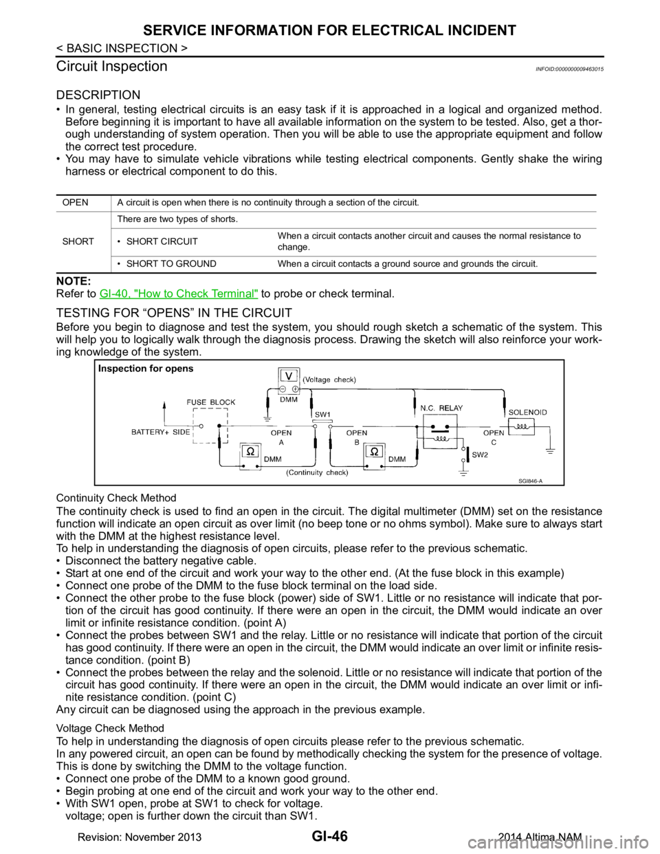
TESTING FOR “OPENS” IN THE CIRCUIT
Before you begin to diagnose and test the system, you should rough sketch a schematic of the system. This
will help you to logically walk through the diagnosis process. Drawing the sketch will also reinforce your work-
ing knowledge of the system.
Continuity Check Method
The continuity check is used to find an open in the circ uit. The digital multimeter (DMM) set on the resistance
function will indicate an open circuit as over limit (no beep tone or no ohms symbol). Make sure to always start
with the DMM at the highest resistance level.
To help in understanding the diagnosis of open circui ts, please refer to the previous schematic.
• Disconnect the battery negative cable.
• Start at one end of the circuit and work your way to the other end. (At the fuse block in this example)
• Connect one probe of the DMM to the fuse block terminal on the load side.
• Connect the other probe to the fuse block (power) side of SW1. Little or no resistance will indicate that por-
tion of the circuit has good continuity. If there were an open in the circuit, the DMM would indicate an over
limit or infinite resistance condition. (point A)
• Connect the probes between SW1 and the relay. Little or no resistance will indicate that portion of the circuit
has good continuity. If there were an open in the circuit, t he DMM would indicate an over limit or infinite resis-
tance condition. (point B)
• Connect the probes between the relay and the solenoid. Little or no resistance will indicate that portion of the
circuit has good continuity. If there were an open in the ci rcuit, the DMM would indicate an over limit or infi-
nite resistance condition. (point C)
Any circuit can be diagnosed using the approach in the previous example.
Voltage Check Method
To help in understanding the diagnosis of open circui ts please refer to the previous schematic.
In any powered circuit, an open can be found by methodica lly checking the system for the presence of voltage.
This is done by switching the DMM to the voltage function.
• Connect one probe of the DMM to a known good ground.
• Begin probing at one end of the circuit and work your way to the other end.
• With SW1 open, probe at SW1 to check for voltage. voltage; open is further down the circuit than SW1.
OPEN A circuit is open when there is no continuity through a section of the circuit.
SHORT There are two types of shorts.
• SHORT CIRCUIT When a circuit contacts another circuit and causes the normal resistance to
change.
• SHORT TO GROUND When a circuit contacts a ground source and grounds the circuit.
SGI846-A
Revision: November 20132014 Altima NAMRevision: November 20132014 Altima NAM
Page 2575 of 4801
SERVICE INFORMATION FOR ELECTRICAL INCIDENTGI-47
< BASIC INSPECTION >
C
D E
F
G H
I
J
K L
M B
GI
N
O P
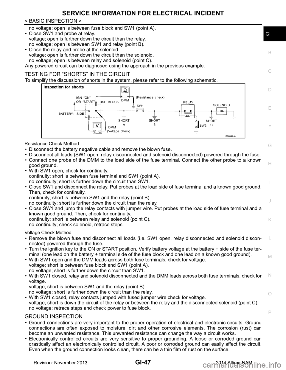
no voltage; open is between fuse block and SW1 (point A).
• Close SW1 and probe at relay. voltage; open is further down the circuit than the relay.
no voltage; open is between SW1 and relay (point B).
• Close the relay and probe at the solenoid. voltage; open is further down the circuit than the solenoid.
no voltage; open is between relay and solenoid (point C).
Any powered circuit can be diagnosed using the approach in the previous example.
TESTING FOR “SHORTS” IN THE CIRCUIT
To simplify the discussion of shorts in the system, please refer to the following schematic.
Resistance Check Method
• Disconnect the battery negative cable and remove the blown fuse.
• Disconnect all loads (SW1 open, relay disconnected and solenoid disconnected) powered through the fuse.
• Connect one probe of the DMM to the load side of the fuse terminal. Connect the other probe to a known
good ground.
• With SW1 open, check for continuity. continuity; short is between fuse terminal and SW1 (point A).
no continuity; short is further down the circuit than SW1.
• Close SW1 and disconnect the relay. Put probes at the load side of fuse terminal and a known good ground. Then, check for continuity.
continuity; short is between SW1 and the relay (point B).
no continuity; short is further down the circuit than the relay.
• Close SW1 and jump the relay contacts with jumper wir e. Put probes at the load side of fuse terminal and a
known good ground. Then, check for continuity.
continuity; short is between relay and solenoid (point C).
no continuity; check solenoid, retrace steps.
Voltage Check Method
• Remove the blown fuse and disconnect all loads (i .e. SW1 open, relay disconnected and solenoid discon-
nected) powered through the fuse.
• Turn the ignition key to the ON or START position. Veri fy battery voltage at the battery + side of the fuse ter-
minal (one lead on the battery + terminal side of the fuse block and one lead on a known good ground).
• With SW1 open and the DMM leads across both fuse terminals, check for voltage.
voltage; short is between fuse block and SW1 (point A).
no voltage; short is further down the circuit than SW1.
• With SW1 closed, relay and solenoid disconnected and t he DMM leads across both fuse terminals, check for
voltage.
voltage; short is between SW1 and the relay (point B).
no voltage; short is further down the circuit than the relay.
• With SW1 closed, relay contacts jumped with fused jumper wire check for voltage. voltage; short is down the circuit of the relay or between the relay and the disconnected solenoid (point C).
no voltage; retrace steps and check power to fuse block.
GROUND INSPECTION
• Ground connections are very important to the proper operation of electrical and electronic circuits. Ground
connections are often exposed to moisture, dirt and ot her corrosive elements. The corrosion (rust) can
become an unwanted resistance. This unwanted re sistance can change the way a circuit works.
• Electronically controlled circuits are very sens itive to proper grounding. A loose or corroded ground can
drastically affect an electronically controlled circuit. A poor or corroded ground can easily affect the circuit.
Even when the ground connection looks clean, there c an be a thin film of rust on the surface.
SGI847-A
Revision: November 20132014 Altima NAMRevision: November 20132014 Altima NAM
Page 2595 of 4801
FRONT DOOR GLASSGW-15
< REMOVAL AND INSTALLATION >
C
D E
F
G H
I
J
L
M A
B
GW
N
O P
Installation is in the reverse order of removal.
• Tighten the front door regulator to glass bolts to specification.
FRONT DOOR GLASS INSPECTION AFTER INSTALLATION
• Check that the door glass is securely set into the glass run groove.
• Lower the door glass slightly [approximately 10 to 20 mm (0.4 to 0.8 in)] and check that the clearance to the
sash is parallel. If the clearance between the door gla ss and sash is not parallel, loosen the regulator bolts,
guide rail bolts, and door glass and guide rail bolts to correct the glass position.
Inspection and AdjustmentINFOID:0000000009463663
SYSTEM INITIALIZATION (IF NECESSARY)
• If any of the following occur, syst em initialization must be performed.
- Electric power supply to power window switch or motor is interrupted by blown fuse or disconnecting battery cable, etc.
- Removal and installation of the regulator assembly.
- Removal and installation of the motor from the regulator assembly.
- Removal and installation of the harness connector of the power window switch.
- Operation of the regulator assembly as a unit.
- Removal and installation of the door glass.
- Removal and installation of the door glass run.
- Window is partly opened and or closed multiple times with out being fully closed.
• To perform system initialization, refer to the following:
- For LH ONLY ANTI-PINCH, refer to PWC-27, "ADDITIONAL SERVICE WHEN REMOVING BATTERY
NEGATIVE TERMINAL : Special Repair Requirement".
- For LH&RH FRONT ANTI-PINCH, refer to PWC-93, "ADDITIONAL SERVICE WHEN REMOVING BAT-
TERY NEGATIVE TERMINAL : Special Repair Requirement".
INSPECT THE FUNCTION OF THE ANTI-PINCH SYSTEM.
To inspect the anti-pinch system, refer to the following:
• For LH ONLY ANTI-PINCH, refer to PWC-27, "ADDITIONAL SERVICE WHEN REMOVING BATTERY
NEGATIVE TERMINAL : Special Repair Requirement".
• For LH&RH FRONT ANTI-PINCH, refer to PWC-93, "ADDITIONAL SERVICE WHEN REMOVING BAT-
TERY NEGATIVE TERMINAL : Special Repair Requirement".
Front door regulator to glass bol
ts : 6.1 N·m (0.62 kg-m, 54 in-lb)
Revision: November 20132014 Altima NAM
Page 2598 of 4801
GW-18
< REMOVAL AND INSTALLATION >
FRONT REGULATOR
Inspection and Adjustment
INFOID:0000000009463666
SYSTEM INITIALIZATION (IF NECESSARY)
• If any of the following occur, sy stem initialization must be performed.
- Electric power supply to power window switch or moto r is interrupted by blown fuse or disconnecting battery
cable, etc.
- Removal and installation of the regulator assembly.
- Removal and installation of the motor from the regulator assembly.
- Removal and installation of the harness connector of the power window switch.
- Operation of the regulator assembly as a unit.
- Removal and installation of the door glass.
- Removal and installation of the door glass run.
- Window is partly opened and or closed multiple times with out being fully closed.
• To perform system initialization, refer to the following:
- For LH ONLY ANTI-PINCH, refer to PWC-27, "ADDITIONAL SERVICE WHEN REMOVING BATTERY
NEGATIVE TERMINAL : Special Repair Requirement".
- For LH&RH FRONT ANTI-PINCH, refer to PWC-93, "ADDITIONAL SERVICE WHEN REMOVING BAT-
TERY NEGATIVE TERMINAL : Special Repair Requirement".
INSPECT THE FUNCTION OF THE ANTI-PINCH SYSTEM.
To inspect the anti-pinch system, refer to the following:
• For LH ONLY ANTI-PINCH, refer to PWC-27, "ADDITIONAL SERVICE WHEN REMOVING BATTERY
NEGATIVE TERMINAL : Special Repair Requirement".
• For LH&RH FRONT ANTI-PINCH, refer to PWC-93, "ADDITIONAL SERVICE WHEN REMOVING BAT-
TERY NEGATIVE TERMINAL : Special Repair Requirement".
Removal and Installation - Front Power Window MotorINFOID:0000000009463667
REMOVAL
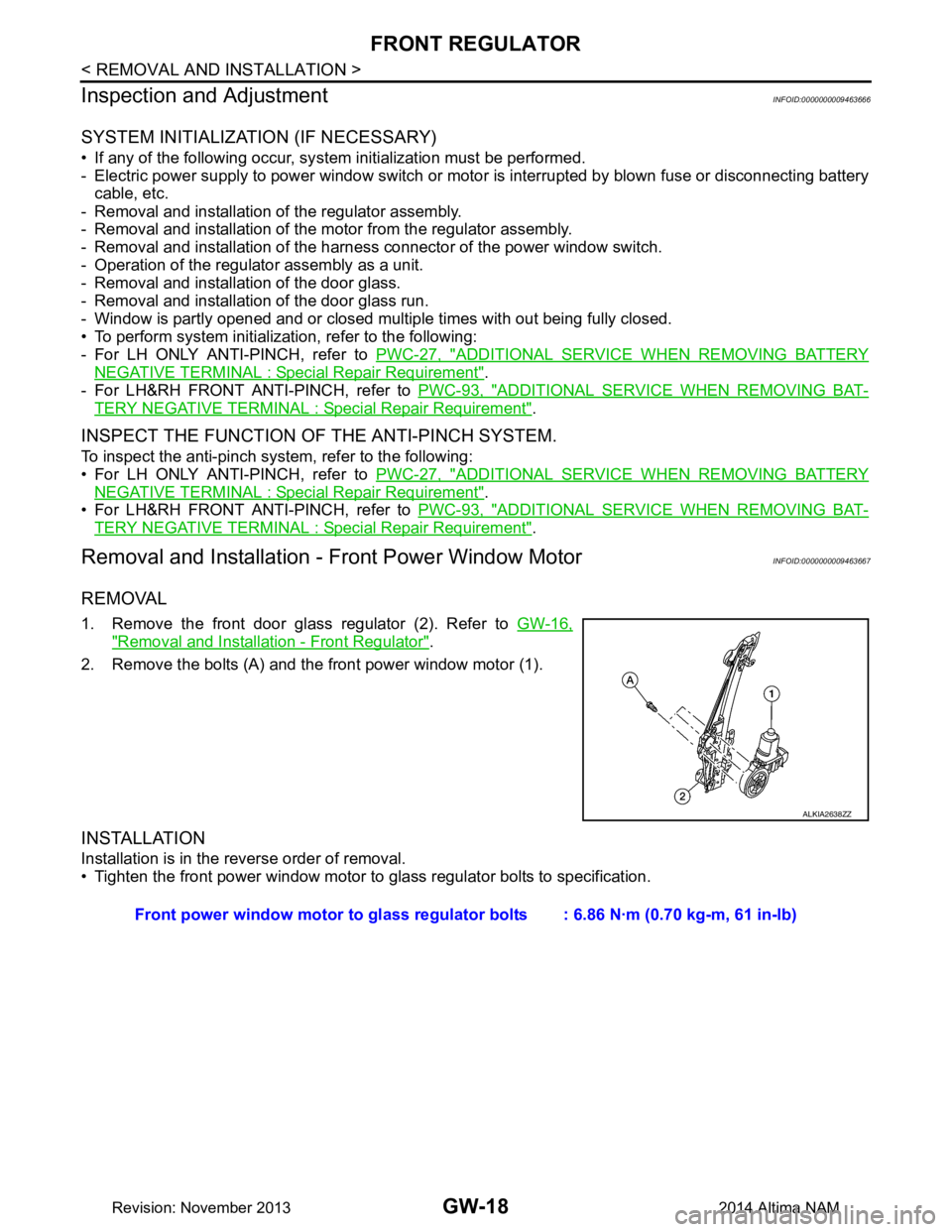
1. Remove the front door glass regulator (2). Refer to GW-16,
"Removal and Installation - Front Regulator".
2. Remove the bolts (A) and the front power window motor (1).
INSTALLATION
Installation is in the reverse order of removal.
• Tighten the front power window motor to glass regulator bolts to specification.
ALKIA2638ZZ
Front power window motor to glass regulator bolts : 6.86 N·m (0.70 kg-m, 61 in-lb)
Revision: November 20132014 Altima NAM
Page 2612 of 4801
HA-6
< PRECAUTION >
PRECAUTIONS
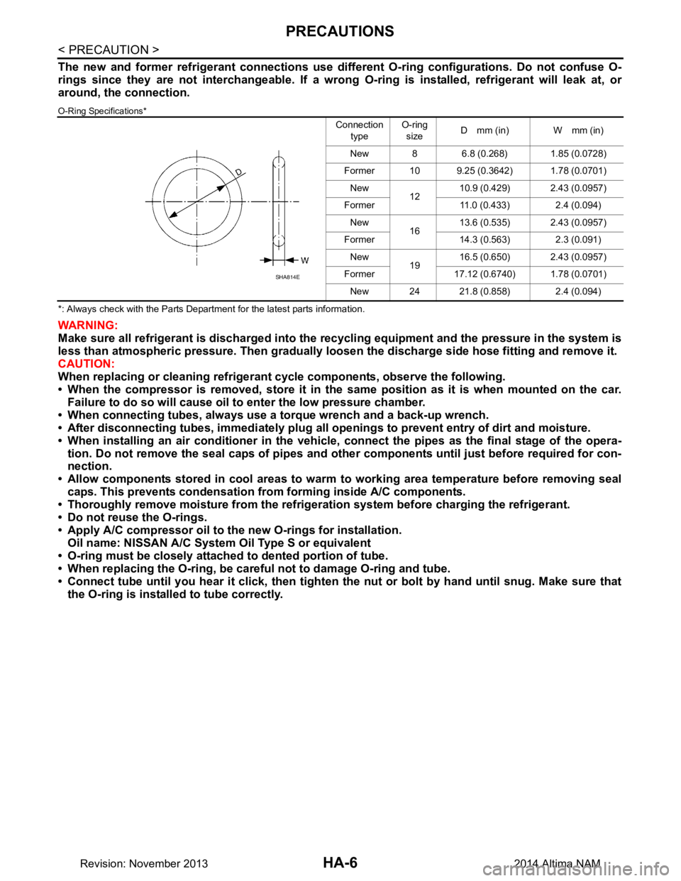
The new and former refrigerant connections use different O-ring configurations. Do not confuse O-
rings since they are not interchangeable. If a wrong O-ring is installed, refrigerant will leak at, or
around, the connection.
O-Ring Specifications*
*: Always check with the Parts Department for the latest parts information.
WARNING:
Make sure all refrigerant is discharged into the recycling equipment and the pressure in the system is
less than atmospheric pressure. Then gradually loo sen the discharge side hose fitting and remove it.
CAUTION:
When replacing or cleaning refrigeran t cycle components, observe the following.
• When the compressor is removed, store it in the same position as it is when mounted on the car.
Failure to do so will cause oil to enter the low pressure chamber.
• When connecting tubes, always use a torque wrench and a back-up wrench.
• After disconnecting tubes, immedi ately plug all openings to prevent entry of dirt and moisture.
• When installing an air conditioner in the vehicle, connect the pipes as the final stage of the opera-
tion. Do not remove the seal caps of pipes and othe r components until just before required for con-
nection.
• Allow components stored in cool areas to warm to working area temperature before removing seal
caps. This prevents condensation from forming inside A/C components.
• Thoroughly remove moisture from the refrigerat ion system before charging the refrigerant.
• Do not reuse the O-rings.
• Apply A/C compressor oil to th e new O-rings for installation.
Oil name: NISSAN A/C System Oil Type S or equivalent
• O-ring must be closely attached to dented portion of tube.
• When replacing the O-ring, be careful not to damage O-ring and tube.
• Connect tube until you hear it cl ick, then tighten the nut or bolt by hand until snug. Make sure that
the O-ring is installed to tube correctly.
Connection
type O-ring
size D mm (in) W mm (in)
New 8 6.8 (0.268) 1.85 (0.0728)
Former 10 9.25 (0.3642) 1.78 (0.0701) New 1210.9 (0.429) 2.43 (0.0957)
Former 11.0 (0.433) 2.4 (0.094) New 1613.6 (0.535) 2.43 (0.0957)
Former 14.3 (0.563) 2.3 (0.091) New 1916.5 (0.650) 2.43 (0.0957)
Former 17.12 (0.6740) 1.78 (0.0701) New 24 21.8 (0.858) 2.4 (0.094)
SHA814E
Revision: November 20132014 Altima NAM
Page 2659 of 4801
![NISSAN TEANA 2014 Service Manual
HAC-10
< SYSTEM DESCRIPTION >[AUTOMATIC AIR CONDITIONER]
COMPONENT PARTS
Component Description
INFOID:0000000009463092
1. ECM 2. IPDM E/R 3. BCM (view with combination meter removed)
4. A/C auto amp NISSAN TEANA 2014 Service Manual
HAC-10
< SYSTEM DESCRIPTION >[AUTOMATIC AIR CONDITIONER]
COMPONENT PARTS
Component Description
INFOID:0000000009463092
1. ECM 2. IPDM E/R 3. BCM (view with combination meter removed)
4. A/C auto amp](/manual-img/5/57390/w960_57390-2658.png)
HAC-10
< SYSTEM DESCRIPTION >[AUTOMATIC AIR CONDITIONER]
COMPONENT PARTS
Component Description
INFOID:0000000009463092
1. ECM 2. IPDM E/R 3. BCM (view with combination meter removed)
4. A/C auto amp. (view with A/C switch assembly removed) 5. A/C switch assembly 6. A/C Compressor
7. Sunload sensor 8. Refrigerant pressure sensor (view with front bumper fascia removed)9. Ambient sensor
10. Fuse Block (J/B), Front blower motor relay 11. In-vehicle sensor 12. Accessory relay-2 (view with instru-
ment panel removed)
13. Blower motor (view with front A/C as- sembly removed from vehicle) 14. Intake door motor 15. Mode door motor
16. Air mix door motor LH 17. Air mix door motor RH 18. Intake sensor
ALIIA0599ZZ
Component Description
A/C auto amp. A/C auto amp. controls front automatic air conditioning system by inputting and calculating signals
from each sensor and each switch.
A/C Compressor Vaporized refrigerant is drawn into the A/C compressor from the evaporator, where it is compressed
to a high pressure, high temperature vapor. The hot, compressed vapor is then discharged to the con-
denser.
A/C switch assembly The A/C switch assembly controls the operation of the A/C and heating system based on inputs from
the temperature control knob, the mode switches, the blower control dial, the ambient temperature
sensor, the intake sensor, and inputs received from the ECM across the CAN. Diagnosis of the A/C
switch assembly can be performed using the CONSULT. There is no self-diagnostic feature available.
Air mix door motor LH The air mix door controls the mix of hot or cold air that enters the ventilation system. It is controlled
by the A/C auto amp. based on the position of the temperature dial. The air mix door motor LH re-
ceives position commands from the A/C auto amp. and reports actual door position back via an LCU
(Local Control Unit) installed inside the motor. Commands and responses are sent across the LIN (Lo-
cal Interconnect Network) to each motor simultaneously, with each motor having its own unique ad-
dress, thereby only responding to requests sent to its specific address. The LCU reads the door
position from a Position Balanced Resistor (PBR), also part of the motor, and returns that information
to the A/C auto amp. The LCU switches the polarity of the circuits connected to the DC motor to drive
the motor forward or backward as requested by the A/C auto amp. If the air mix door moves to a po-
sition less than 5% or more than 95% of its expected or allowed positions, the A/C auto amp. will set
a DTC.
Revision: November 20132014 Altima NAMRevision: November 20132014 Altima NAM