2014 NISSAN TEANA fuse
[x] Cancel search: fusePage 2364 of 4801

EXL-98
< DTC/CIRCUIT DIAGNOSIS >
DAYTIME LIGHT RELAY CIRCUIT
DAYTIME LIGHT RELAY CIRCUIT
DescriptionINFOID:0000000009463588
The BCM sends a daytime light request to the IPDM E/R via the CAN communication lines. The power flows
through fuse 43 located in IPDM E/R to the daytime li ght relay coil. When the IPDM E/R operates the daytime
light relay, power is sent to the daytime lamps.
Diagnosis ProcedureINFOID:0000000009463589
Regarding Wiring Diagram information, refer to EXL-39, "Wiring Diagram".
1.CHECK DAYTIME LIGHT RELAY VOLTAGE SUPPLY
1. Turn the ignition switch OFF.
2. Remove the daytime light relay.
3. Check the voltage between the daytime light relay harness connector E228 and ground.
Is the inspection result normal?
YES >> GO TO 3.
NO >> GO TO 2.
2.CHECK DAYTIME LIGHT RELAY CIRCUIT
1. Turn the ignition switch OFF.
2. Disconnect IPDM E/R harness connector E18.
3. Check continuity between the IPDM E/R harness c onnector E18 and the daytime light relay harness con-
nector E228.
4. Check continuity between the IP DM E/R harness connector E18 and ground.
Is the inspection result normal?
YES >> Replace IPDM E/R. Refer to PCS-32, "Removal and Installation".
NO >> Repair or replace the harness or connector.
3.CHECK DAYTIME LIGHT RELAY CONTROL CIRCUIT
1. Turn the ignition switch OFF.
2. Check continuity between the IPDM E/R harness connector E201 and the daytime light relay harness
connector E228.
Daytime light relay (− )Voltage
Connector Terminal
E228 2
Ground Battery voltage
5
Daytime light relay IPDM E/R Continuity
Connector Terminal Connector Terminal
E228 2
E18 14 Ye s
5
Connector Terminal — Continuity
E18 14 Ground No
Daytime light relay IPDM E/R Continuity
Connector Terminal Connector Terminal
E228 1 E201 85 Yes
Revision: November 20132014 Altima NAMRevision: November 20132014 Altima NAM
Page 2367 of 4801
FRONT FOG LAMP CIRCUITEXL-101
< DTC/CIRCUIT DIAGNOSIS >
C
D E
F
G H
I
J
K
M A
B
EXL
N
O P
FRONT FOG LAMP CIRCUIT
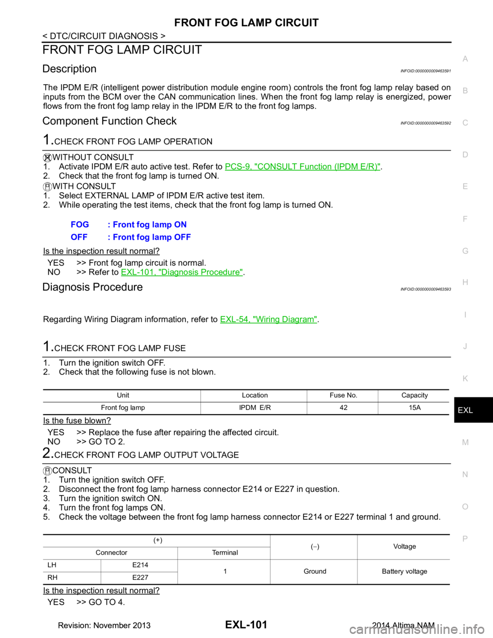
DescriptionINFOID:0000000009463591
The IPDM E/R (intelligent power di stribution module engine room) controls the front fog lamp relay based on
inputs from the BCM over the CAN communication lines . When the front fog lamp relay is energized, power
flows from the front fog lamp relay in the IPDM E/R to the front fog lamps.
Component Function CheckINFOID:0000000009463592
1.CHECK FRONT FOG LAMP OPERATION
WITHOUT CONSULT
1. Activate IPDM E/R auto active test. Refer to PCS-9, "CONSULT Function (IPDM E/R)"
.
2. Check that the front fog lamp is turned ON.
WITH CONSULT
1. Select EXTERNAL LAMP of IP DM E/R active test item.
2. While operating the test items, check that the front fog lamp is turned ON.
Is the inspection result normal?
YES >> Front fog lamp circuit is normal.
NO >> Refer to EXL-101, "Diagnosis Procedure"
.
Diagnosis ProcedureINFOID:0000000009463593
Regarding Wiring Diagram information, refer to EXL-54, "Wiring Diagram".
1.CHECK FRONT FOG LAMP FUSE
1. Turn the ignition switch OFF.
2. Check that the following fuse is not blown.
Is the fuse blown?
YES >> Replace the fuse after repairing the affected circuit.
NO >> GO TO 2.
2.CHECK FRONT FOG LAMP OUTPUT VOLTAGE
CONSULT
1. Turn the ignition switch OFF.
2. Disconnect the front fog lamp harness connector E214 or E227 in question.
3. Turn the ignition switch ON.
4. Turn the front fog lamps ON.
5. Check the voltage between the front fog lamp harness connector E214 or E227 terminal 1 and ground.
Is the inspection result normal?
YES >> GO TO 4. FOG : Front fog lamp ON
OFF : Front fog lamp OFF
Unit Location Fuse No. Capacity
Front fog lamp IPDM E/R 42 15A
(+) (− )Voltage
Connector Terminal
LH E214 1 Ground Battery voltage
RH E227
Revision: November 20132014 Altima NAMRevision: November 20132014 Altima NAM
Page 2369 of 4801
PARKING LAMP CIRCUITEXL-103
< DTC/CIRCUIT DIAGNOSIS >
C
D E
F
G H
I
J
K
M A
B
EXL
N
O P
PARKING LAMP CIRCUIT
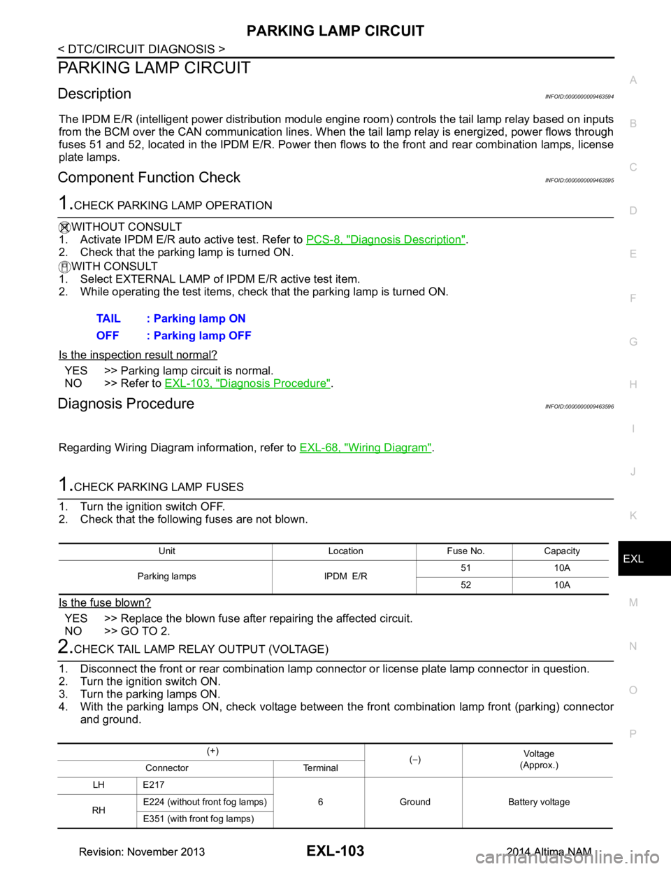
DescriptionINFOID:0000000009463594
The IPDM E/R (intelligent power distribution module engi ne room) controls the tail lamp relay based on inputs
from the BCM over the CAN communication lines. When t he tail lamp relay is energized, power flows through
fuses 51 and 52, located in the IPDM E/R. Power then fl ows to the front and rear combination lamps, license
plate lamps.
Component Function CheckINFOID:0000000009463595
1.CHECK PARKING LAMP OPERATION
WITHOUT CONSULT
1. Activate IPDM E/R auto active test. Refer to PCS-8, "Diagnosis Description"
.
2. Check that the parking lamp is turned ON.
WITH CONSULT
1. Select EXTERNAL LAMP of IP DM E/R active test item.
2. While operating the test items, check that the parking lamp is turned ON.
Is the inspection result normal?
YES >> Parking lamp circuit is normal.
NO >> Refer to EXL-103, "Diagnosis Procedure"
.
Diagnosis ProcedureINFOID:0000000009463596
Regarding Wiring Diagram information, refer to EXL-68, "Wiring Diagram".
1.CHECK PARKING LAMP FUSES
1. Turn the ignition switch OFF.
2. Check that the following fuses are not blown.
Is the fuse blown?
YES >> Replace the blown fuse after repairing the affected circuit.
NO >> GO TO 2.
2.CHECK TAIL LAMP RELAY OUTPUT (VOLTAGE)
1. Disconnect the front or rear combination lamp connector or license plate lamp connector in question.
2. Turn the ignition switch ON.
3. Turn the parking lamps ON.
4. With the parking lamps ON, check voltage between t he front combination lamp front (parking) connector
and ground. TAIL : Parking lamp ON
OFF : Parking lamp OFF
Unit Location Fuse No. Capacity
Parking lamps IPDM E/R 51 10A
52 10A
(+) (− ) Vo l ta g e
(Approx.)
Connector Terminal
LH E217 6 Ground Battery voltage
RH E224 (without front fog lamps)
E351 (with front fog lamps)
Revision: November 20132014 Altima NAMRevision: November 20132014 Altima NAM
Page 2380 of 4801
EXL-114
< SYMPTOM DIAGNOSIS >
EXTERIOR LIGHTING SYSTEM SYMPTOMS
SYMPTOM DIAGNOSIS
EXTERIOR LIGHTING SYSTEM SYMPTOMS
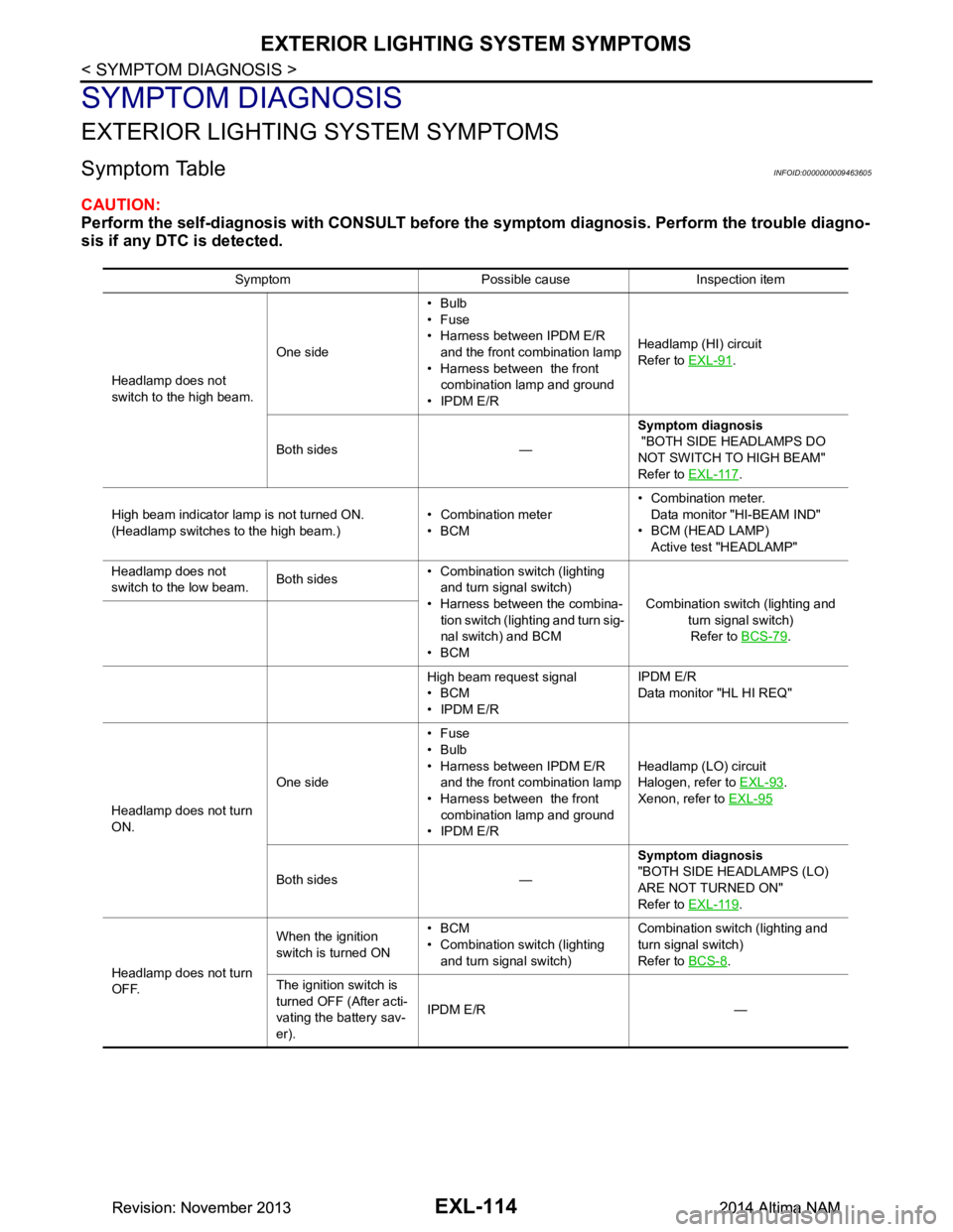
Symptom TableINFOID:0000000009463605
CAUTION:
Perform the self-diagnosis with CONSULT before th e symptom diagnosis. Perform the trouble diagno-
sis if any DTC is detected.
Symptom Possible cause Inspection item
Headlamp does not
switch to the high beam. One side•Bulb
•Fuse
• Harness between IPDM E/R and the front combination lamp
• Harness between the front combination lamp and ground
• IPDM E/R Headlamp (HI) circuit
Refer to EXL-91
.
Both sides — Symptom diagnosis
"BOTH SIDE HEADLAMPS DO
NOT SWITCH TO HIGH BEAM"
Refer to EXL-117
.
High beam indicator lamp is not turned ON.
(Headlamp switches to the high beam.) • Combination meter
•BCM • Combination meter.
Data monitor "HI-BEAM IND"
• BCM (HEAD LAMP) Active test "HEADLAMP"
Headlamp does not
switch to the low beam. Both sides• Combination switch (lighting
and turn signal switch)
• Harness between the combina- tion switch (lighting and turn sig-
nal switch) and BCM
•BCM Combination switch (lighting and
turn signal switch)Refer to BCS-79
.
High beam request signal
•BCM
• IPDM E/R IPDM E/R
Data monitor "HL HI REQ"
Headlamp does not turn
ON. One side•Fuse
•Bulb
• Harness between IPDM E/R and the front combination lamp
• Harness between the front combination lamp and ground
• IPDM E/R Headlamp (L
O) circuit
Halogen, refer to EXL-93
.
Xenon, refer to EXL-95
Both sides — Symptom diagnosis
"BOTH SIDE HEADLAMPS (LO)
ARE NOT TURNED ON"
Refer to EXL-119
.
Headlamp does not turn
OFF. When the ignition
switch is turned ON •BCM
• Combination switch (lighting and turn signal switch) Combination switch (lighting and
turn signal switch)
Refer to BCS-8
.
The ignition switch is
turned OFF (After acti-
vating the battery sav-
er). IPDM E/R —
Revision: November 20132014 Altima NAMRevision: November 20132014 Altima NAM
Page 2381 of 4801
EXTERIOR LIGHTING SYSTEM SYMPTOMSEXL-115
< SYMPTOM DIAGNOSIS >
C
D E
F
G H
I
J
K
M A
B
EXL
N
O P
Headlamp is not turned ON/OFF with the lighting
switch AUTO. • Combination switch (lighting
and turn signal switch)
• Harness between the combina- tion switch (lighting and turn sig-
nal switch) and BCM
•BCM
• IPDM E/R Combination switch (lighting and
turn signal switch)
Refer to BCS-79.
• Optical sensor
• Harness between the optical
sensor and BCM
•BCM Optical sensor
Refer to EXL-110
.
Daytime light system does not activate. —Symptom diagnosis
"DAYTIME LIGHT SYSTEM INOP-
ERATIVE"
Refer to EXL-118
.
Front fog lamp is not
turned ON. One side
• Front fog lamp bulb
• Harness between IPDM E/R
and the front fog lamp
• Harness between the front fog lamp and ground
• IPDM E/R Front fog lamp circuit
Refer to EXL-101
.
Both side — Symptom diagnosis
"BOTH SIDE FRONT FOG LAMPS
ARE NOT TURNED ON"
Refer to EXL-121
.
Parking lamp is not turned
ON. One side•Fuse
• Parking lamp bulb
• Harness between IPDM E/R
and the front/rear combination
lamp
• Harness between the front/rear
combination lamp and ground
• IPDM E/R Parking lamp circuit
Refer to EXL-103
.
Both sides — Symptom diagnosis
"PARKING, LICENSE PLATE AND
TAIL LAMPS ARE NOT TURNED
ON"
Refer to EXL-120
.
Turn signal lamp does not
blink. Indicator lamp is nor-
mal.
(The applicable side
performs the high flash-
er activation). • Harness between BCM and
each turn signal lamp
• Turn signal lamp bulb
• Door mirror (if equipped with
turn signals in the door mirrors) Turn signal lamp circuit
Refer to EXL-106
.
Turn signal indicator lamp
does not blink. One side Combination meter —
Both sides
(Always) • Turn signal indicator lamp sig-
nal
• Combination meter
•BCM • Combination meter.
Data monitor "TURN IND"
• BCM (FLASHER) Active test "FLASHER"
Both sides
(Does blink when acti-
vating the hazard warn-
ing lamp with the
ignition switch OFF) • The combination meter power
supply and the ground circuit
• Combination meter Combination meter
Power supply and the ground circuit
Refer to MWI-58
.
• Hazard warning lamp does not activate.
• Hazard warning lamp continues activating. (Turn signal is normal) • Hazard switch
• Harness between the hazard switch and BCM
•BCM Hazard switch
Refer to EXL-112
.
Symptom Possible cause Inspection item
Revision: November 20132014 Altima NAMRevision: November 20132014 Altima NAM
Page 2384 of 4801
EXL-118
< SYMPTOM DIAGNOSIS >
DAYTIME LIGHT SYSTEM INOPERATIVE
DAYTIME LIGHT SYSTEM INOPERATIVE
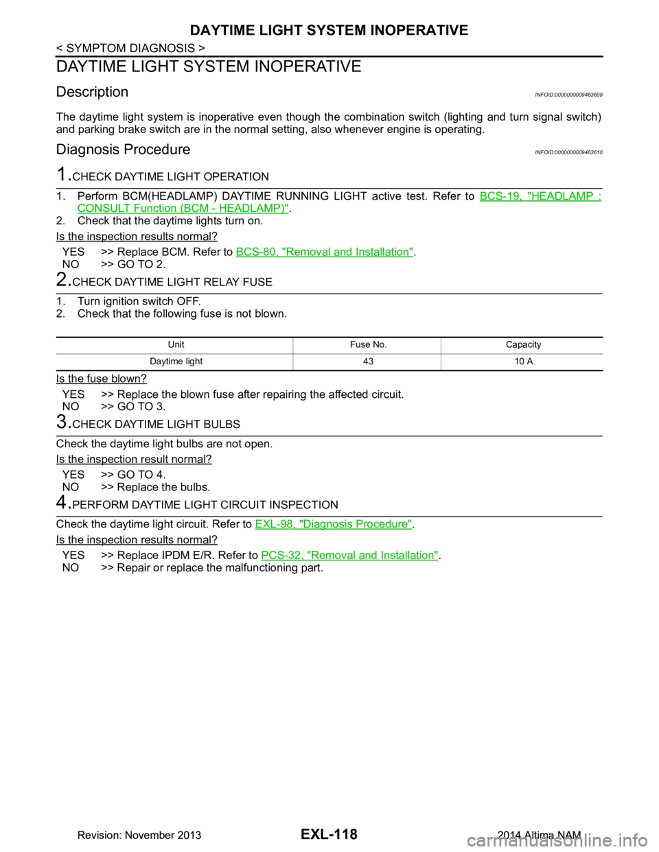
DescriptionINFOID:0000000009463609
The daytime light system is inoperative even though the combination switch (lighting and turn signal switch)
and parking brake switch are in the normal setting, also whenever engine is operating.
Diagnosis ProcedureINFOID:0000000009463610
1.CHECK DAYTIME LIGHT OPERATION
1. Perform BCM(HEADLAMP) DAYTIME RUNNING LIGHT active test. Refer to BCS-19, "HEADLAMP :
CONSULT Function (BCM - HEADLAMP)".
2. Check that the daytime lights turn on.
Is the inspection results normal?
YES >> Replace BCM. Refer to BCS-80, "Removal and Installation".
NO >> GO TO 2.
2.CHECK DAYTIME LIGHT RELAY FUSE
1. Turn ignition switch OFF.
2. Check that the following fuse is not blown.
Is the fuse blown?
YES >> Replace the blown fuse after repairing the affected circuit.
NO >> GO TO 3.
3.CHECK DAYTIME LIGHT BULBS
Check the daytime light bulbs are not open.
Is the inspection result normal?
YES >> GO TO 4.
NO >> Replace the bulbs.
4.PERFORM DAYTIME LIGH T CIRCUIT INSPECTION
Check the daytime light circuit. Refer to EXL-98, "Diagnosis Procedure"
.
Is the inspection results normal?
YES >> Replace IPDM E/R. Refer to PCS-32, "Removal and Installation".
NO >> Repair or replace the malfunctioning part.
Unit Fuse No. Capacity
Daytime light 43 10 A
Revision: November 20132014 Altima NAMRevision: November 20132014 Altima NAM
Page 2393 of 4801
FRONT COMBINATION LAMPEXL-127
< REMOVAL AND INSTALLATION >
C
D E
F
G H
I
J
K
M A
B
EXL
N
O P
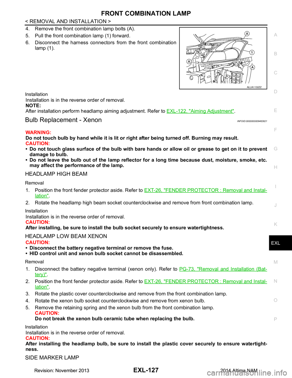
4. Remove the front combination lamp bolts (A).
5. Pull the front combination lamp (1) forward.
6. Disconnect the harness connectors from the front combination
lamp (1).
Installation
Installation is in the reverse order of removal.
NOTE:
After installation perform headlamp aiming adjustment. Refer to EXL-122, "Aiming Adjustment"
.
Bulb Replacement - XenonINFOID:0000000009463621
WARNING:
Do not touch bulb by hand while it is lit or right after being turned off. Burning may result.
CAUTION:
• Do not touch glass surface of the bulb with bare hand s or allow oil or grease to get on it to prevent
damage to bulb.
• Do not leave the bulb out of the lamp reflector fo r a long time because dust, moisture, smoke, etc.
may affect the performance of the lamp.
HEADLAMP HIGH BEAM
Removal
1. Position the front fender pr otector aside. Refer to EXT-26, "FENDER PROTECTOR : Removal and Instal-
lation".
2. Rotate the headlamp high beam socket countercloc kwise and remove from front combination lamp.
Installation
Installation is in the reverse order of removal.
CAUTION:
After installing, be sure to install the bulb socket securely to ensure watertightness.
HEADLAMP LOW BEAM XENON
CAUTION:
• Disconnect the battery negative terminal or remove the fuse.
• HID control unit and xenon bu lb socket cannot be disassembled.
Removal
1. Disconnect the battery negative te rminal (xenon only). Refer to PG-73, "Removal and Installation (Bat-
tery)".
2. Position the front fender pr otector aside. Refer to EXT-26, "FENDER PROTECTOR : Removal and Instal-
lation".
3. Rotate the plastic cover counterclockwise and remove from the front combination lamp.
4. Rotate the xenon bulb socket counterclockwise and remove from xenon bulb.
5. Remove the retaining spring and the xenon bulb from the front combination lamp. CAUTION:
Do not break the xenon bulb ceramic tube when replacing the bulb.
Installation
Installation is in the reverse order of removal.
CAUTION:
After installing the headlamp bulb, be sure to inst all the plastic cover securely to ensure watertight-
ness.
SIDE MARKER LAMP
ALLIA1132ZZ
Revision: November 20132014 Altima NAMRevision: November 20132014 Altima NAM
Page 2408 of 4801
EXL-142
< UNIT DISASSEMBLY AND ASSEMBLY >
FRONT COMBINATION LAMP
UNIT DISASSEMBLY AND ASSEMBLY
FRONT COMBINATION LAMP
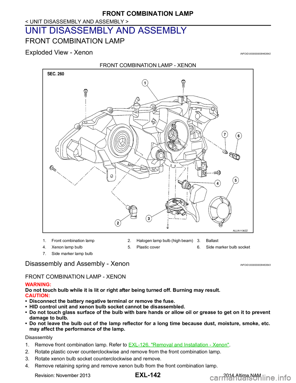
Exploded View - XenonINFOID:0000000009463642
FRONT COMBINATION LAMP - XENON
Disassembly and Assembly - XenonINFOID:0000000009463643
FRONT COMBINATION LAMP - XENON
WARNING:
Do not touch bulb while it is lit or right after being turned off. Burning may result.
CAUTION:
• Disconnect the battery negative terminal or remove the fuse.
• HID control unit and xenon bu lb socket cannot be disassembled.
• Do not touch glass surface of the bulb with bare hands or allow oil or grease to get on it to prevent
damage to bulb.
• Do not leave the bulb out of the lamp reflector fo r a long time because dust, moisture, smoke, etc.
may affect the performance of the lamp.
Disassembly
1. Remove front combination lamp. Refer to EXL-126, "Removal and Installation - Xenon".
2. Rotate plastic cover counterclockwise and remove from the front combination lamp.
3. Rotate xenon bulb socket counterclockwise and remove.
4. Remove retaining spring and remove xenon bulb from the front combination lamp.
ALLIA1136ZZ
1. Front combination lamp 2. Halogen lamp bulb (high beam) 3. Ballast
4. Xenon lamp bulb 5. Plastic cover 6. Side marker bulb socket
7. Side marker lamp bulb
Revision: November 20132014 Altima NAMRevision: November 20132014 Altima NAM