2014 NISSAN TEANA fuse
[x] Cancel search: fusePage 2270 of 4801
EXL-4
< PRECAUTION >
PRECAUTIONS
PRECAUTION
PRECAUTIONS
Precaution for Supplemental Restraint System (SRS) "AIR BAG" and "SEAT BELT
PRE-TENSIONER"
INFOID:0000000009951582
The Supplemental Restraint System such as “A IR BAG” and “SEAT BELT PRE-TENSIONER”, used along
with a front seat belt, helps to reduce the risk or severi ty of injury to the driver and front passenger for certain
types of collision. Information necessary to service the system safely is included in the SR and SB section of
this Service Manual.
WARNING:
• To avoid rendering the SRS inopera tive, which could increase the risk of personal injury or death in
the event of a collision which would result in air bag inflation, all maintenance must be performed by
an authorized NISS AN/INFINITI dealer.
• Improper maintenance, including in correct removal and installation of the SRS, can lead to personal
injury caused by unintent ional activation of the system. For re moval of Spiral Cable and Air Bag
Module, see the SR section.
• Do not use electrical test equipmen t on any circuit related to the SRS unless instructed to in this
Service Manual. SRS wiring harn esses can be identified by yellow and/or orange harnesses or har-
ness connectors.
PRECAUTIONS WHEN USING POWER TOOLS (AIR OR ELECTRIC) AND HAMMERS
WARNING:
• When working near the Airbag Diagnosis Sensor Unit or other Airbag System sensors with the Igni-
tion ON or engine running, DO NOT use air or electri c power tools or strike near the sensor(s) with a
hammer. Heavy vibration could activate the sensor( s) and deploy the air bag(s), possibly causing
serious injury.
• When using air or electric power tools or hammers , always switch the Ignition OFF, disconnect the
battery and wait at least three minutes before performing any service.
General precautions fo r service operationsINFOID:0000000009463538
• Do not work with wet hands.
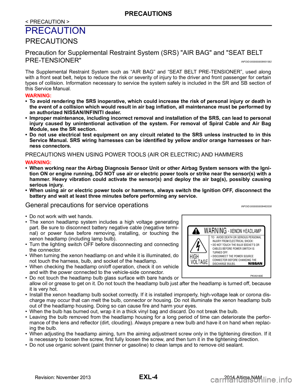
• The xenon headlamp system includes a high voltage generating
part. Be sure to disconnect batte ry negative cable (negative termi-
nal) or power fuse before removing, installing, or touching the
xenon headlamp (including lamp bulb).
• Turn the lighting switch OFF before disconnecting and connecting the connector.
• When turning the xenon headlamp on and while it is illuminated, do
not touch the harness, bulb, and socket of the headlamp.
• When checking the headlamp on/off operation, check it on vehicle and with the power connected to the vehicle-side connector.
• Do not touch the headlamp bulb glass surface with bare hands or allow oil or grease to get on it. Do not touch the headl amp bulb just after the headlamp is turned off, because
it is very hot.
• Install the xenon headlamp bulb socket co rrectly. If it is installed improperly, high-voltage leak or corona dis-
charge may occur that can melt the bulb, connector or housing. Do not illuminate the xenon headlamp bulb
out of the headlamp housing. Doing so can cause fire and harm your eyes.
• When the bulb has burned out, wrap it in a thick vinyl bag and discard. Do not break the bulb.
• Leaving the bulb removed from the headlamp housing for a long period of time can deteriorate the perfor- mance of the lens and reflector (dirt, clouding). Al ways prepare a new bulb and have it on hand when replac-
ing the bulb.
• When adjusting the headlamp aiming, turn the aiming adjus tment screw only in the tightening direction. If it
is necessary to loosen the screw, first fully loosen the screw, and then turn it in the tightening direction.
• Do not use organic solvent (paint thinner or gasoline) to clean lamps and to remove old sealant.
PKIA0183E
Revision: November 20132014 Altima NAMRevision: November 20132014 Altima NAM
Page 2274 of 4801

EXL-8
< SYSTEM DESCRIPTION >
COMPONENT PARTS
Component Description
INFOID:0000000009463542
1. BCM (view with combination meter re-
moved) 2. Combination switch
(lighting and turn signal switch) 3. IPDM E/R, (Headlamp high relay,
Headlamp low relay, Tail lamp relay
and Front fog lamp relay (if equipped))
4. Fuse, fusible link and relay box (Stop lamp relay) 5. Combination meter 6. Parking brake switch
7. Stop lamp switch 8. Hazard switch 9. Optical sensor
10. Front door switch LH (RH similar) 11. Rear door switch LH
(RH similar) 12. Daytime light relay
(if equipped)
Part Description
BCM Controls the exterior lighting system.
Combination switch
(Lighting & turn signal switch) Refer to
BCS-8, "COMBINATION SWITCH READIN G SYSTEM : System Description"
.
IPDM E/R Controls the integrated relays and supplies voltage to the load according to the request from the BCM
via CAN communication.
Stop lamp switch Transmits power to the stop lamp relay when the brake pedal is pressed to operate stop lamps.
Combination meter Refer to MWI-9, "METER SYSTEM : System Description"
.
Daytime light relay
(if equipped) Sends power to the daytime lamp when operated by the IPDM E/R.
Stop lamp relay Transmits power to the stop lamps when the brake pedal is pressed.
Front door switch LH/RH Transmits the door open signal to the BCM.
Rear door switch LH/RH
Optical sensor Optical sensor converts the outside brightness (lux) to voltage and transmits the optical sensor signal
to BCM to operate the auto light system.
Parking brake switch Transmits the parking brake switch signal to the combination meter to operate the auto light system.
Hazard switch Inputs the hazard switch signal to BCM.
Revision: November 20132014 Altima NAMRevision: November 20132014 Altima NAM
Page 2355 of 4801
POWER SUPPLY AND GROUND CIRCUITEXL-89
< DTC/CIRCUIT DIAGNOSIS >
C
D E
F
G H
I
J
K
M A
B
EXL
N
O P
DTC/CIRCUIT DIAGNOSIS
POWER SUPPLY AND GROUND CIRCUIT
BCM (BODY CONTROL MODULE)
BCM (BODY CONTROL MODULE) : Diagnosis ProcedureINFOID:0000000009956493
Regarding Wiring Diagram information, refer to BCS-55, "Wiring Diagram".
1. CHECK FUSE AND FUSIBLE LINK
Check that the following fuse and fusible link are not blown.
Is the fuse or fusible link blown?
YES >> Replace the blown fuse or fusible link after repairing the affected circuit.
NO >> GO TO 2
2. CHECK POWER SUPPLY CIRCUIT
1. Disconnect BCM connector M21.
2. Check voltage between BCM connector M21 terminals 131, 139 and ground.
Is the inspection result normal?
YES >> GO TO 3
NO >> Repair or replace harness or connectors.
3. CHECK GROUND CIRCUIT
Check continuity between BCM connector M21 terminals 134, 143 and ground.
Is the inspection result normal?
YES >> Inspection End.
NO >> Repair or replace harness or connectors.
IPDM E/R (INTELLIGENT POWER DIST RIBUTION MODULE ENGINE ROOM)
IPDM E/R (INTELLIGENT POWER DISTRIBUTION MODULE ENGINE ROOM) : Di-
agnosis Procedure
INFOID:0000000009956494
Regarding Wiring Diagram information, refer to PCS-21, "Wiring Diagram".
Terminal No. Signal name Fuse and fusible link No.
139 Fusible link battery power I (40A)
131 BCM battery fuse 1 (10A)
BCM GroundVo l ta g e
(Approx.)
Connector Terminal
M21 131
—Batteryvoltage
139
BCM Ground Continuity
Connector Terminal
M21 134
—Yes
143
Revision: November 20132014 Altima NAMRevision: November 20132014 Altima NAM
Page 2357 of 4801
HEADLAMP (HI) CIRCUITEXL-91
< DTC/CIRCUIT DIAGNOSIS >
C
D E
F
G H
I
J
K
M A
B
EXL
N
O P
HEADLAMP (HI) CIRCUIT
DescriptionINFOID:0000000009463577
The IPDM E/R (intelligent power distribution modul e engine room) controls the headlamp high relay based on
inputs from the BCM over the CAN communication li nes. When the headlamp high relay is energized, power
flows through fuses 34 and 35, located in the IPDM E/R. Power then flows to the front combination lamps to
the headlamp high beam.
Component Function CheckINFOID:0000000009463578
1.CHECK HEADLAMP (HI) OPERATION
WITHOUT CONSULT
1. Start IPDM E/R auto active test. Refer to PCS-8, "Diagnosis Description"
.
2. Check that the headlamp switches to the high beam. NOTE:
HI/LO is repeated 1 second each when using the IPDM E/R auto active test.
CONSULT
1. Select EXTERNAL LAMP of IP DM E/R active test item.
2. While operating the test items, check t hat the headlamp switches to the high beam.
Is the inspection result normal?
YES >> Headlamp (HI) circuit is normal.
NO >> Refer to EXL-91, "Diagnosis Procedure"
.
Diagnosis ProcedureINFOID:0000000009463579
Regarding Wiring Diagram information, refer to EXL-27, "Wiring Diagram - Halogen" or EXL-33, "Wiring Dia-
gram - Xenon".
1.CHECK HEADLAMP (HI) FUSES
1. Turn the ignition switch OFF.
2. Check that the following fuses are not blown.
Is the fuse blown?
YES >> Replace the fuse after repairing the affected circuit.
NO >> GO TO 2.
2.CHECK HEADLAMP (HI) OUTPUT VOLTAGE
CONSULT ACTIVE TEST
1. Turn the ignition switch OFF.
2. Disconnect the front combination lamp harness connector E213 or E222 in question.
3. Turn the ignition switch ON.
4. Select EXTERNAL LAMP of IP DM E/R active test item.
5. With EXTERNAL LAMP ON, check the voltage between the combination lamp connector and ground.
HI : Headlamp switches to the high beam.
OFF : Headlamp OFF
Unit Location Fuse No. Capacity
Headlamp HI (LH) IPDM E/R 35 10A
Headlamp HI (RH) IPDM E/R 34 10A
Revision: November 20132014 Altima NAMRevision: November 20132014 Altima NAM
Page 2359 of 4801
HEADLAMP (LO) CIRCUITEXL-93
< DTC/CIRCUIT DIAGNOSIS >
C
D E
F
G H
I
J
K
M A
B
EXL
N
O P
HEADLAMP (LO) CIRCUIT
HEADLAMP (HALOGEN)
HEADLAMP (HALOGEN) : DescriptionINFOID:0000000009463580
The IPDM E/R (intelligent power distribution modul e engine room) controls the headlamp low relay based on
inputs from the BCM over the CAN communication li nes. When the headlamp low relay is energized, power
flows through fuses 36 and 37, located in the IPDM E/R. Power then flows to the front combination lamps to
the headlamp low beam.
HEADLAMP (HALOGEN) : Component Function CheckINFOID:0000000009463581
1.CHECK HEADLAMP (LO) OPERATION
WITHOUT CONSULT
1. Start IPDM E/R auto active test. Refer to PCS-8, "Diagnosis Description"
.
2. Check that the headlamp is turned ON.
NOTE:
HI/LO is repeated 1 second each when using the IPDM E/R auto active test.
CONSULT
1. Select EXTERNAL LAMP of IP DM E/R active test item.
2. While operating the test items, check that the headlamp is turned ON.
Is the inspection result normal?
YES >> Headlamp (LO) is normal.
NO >> Refer to EXL-93, "HEADLAMP (HALOGEN) : Diagnosis Procedure"
.
HEADLAMP (HALOGEN) : Diagnosis ProcedureINFOID:0000000009463582
Regarding Wiring Diagram information, refer to EXL-27, "Wiring Diagram - Halogen".
1.CHECK HEADLAMP (LO) FUSES
1. Turn the ignition switch OFF.
2. Check that the following fuses are not blown.
Is the fuse blown?
YES >> Replace the fuse after repairing the affected circuit.
NO >> GO TO 2.
2.CHECK HEADLAMP (LO) OUTPUT VOLTAGE
CONSULT
1. Turn the ignition switch OFF.
2. Disconnect the front combination lamp harness connector E212 or E223 in question.
3. Turn the ignition switch ON.
4. Select EXTERNAL LAMP of IP DM E/R active test item.
5. With EXTERNAL LAMP ON, check the voltage betw een the combination lamp connector E212 or E223
terminal 1 and ground. LO : Headlamp ON
OFF : Headlamp OFF
Unit Location Fuse No. Capacity
Headlamp LO (RH) IPDM E/R 36 15A
Headlamp LO (L H) IPDM E/R 37 15A
Revision: November 20132014 Altima NAMRevision: November 20132014 Altima NAM
Page 2360 of 4801
EXL-94
< DTC/CIRCUIT DIAGNOSIS >
HEADLAMP (LO) CIRCUIT
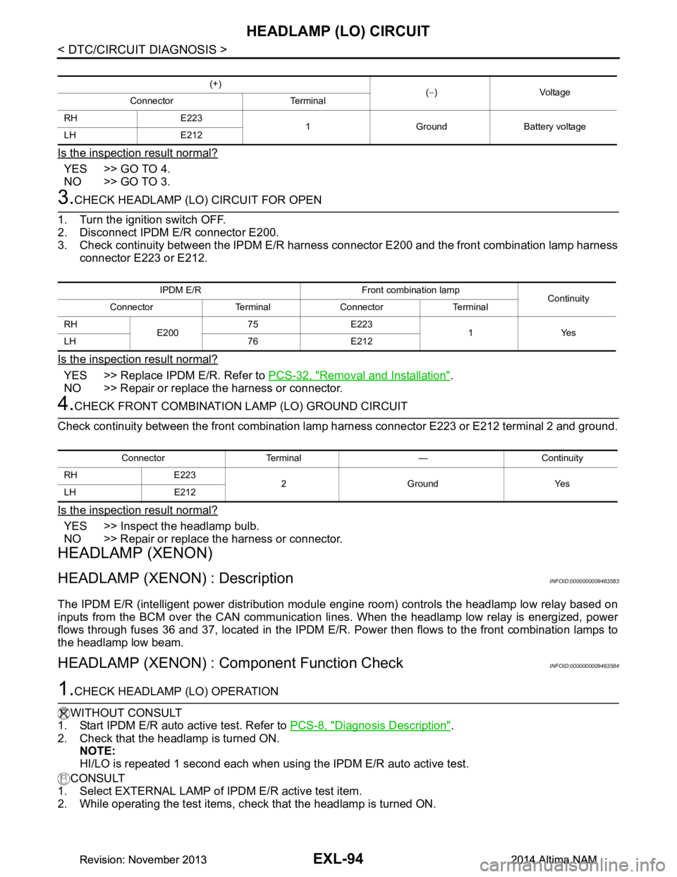
Is the inspection result normal?
YES >> GO TO 4.
NO >> GO TO 3.
3.CHECK HEADLAMP (LO) CIRCUIT FOR OPEN
1. Turn the ignition switch OFF.
2. Disconnect IPDM E/R connector E200.
3. Check continuity between the IPDM E/R harness c onnector E200 and the front combination lamp harness
connector E223 or E212.
Is the inspection result normal?
YES >> Replace IPDM E/R. Refer to PCS-32, "Removal and Installation".
NO >> Repair or replace the harness or connector.
4.CHECK FRONT COMBINATION LAMP (LO) GROUND CIRCUIT
Check continuity between the front combination la mp harness connector E223 or E212 terminal 2 and ground.
Is the inspection result normal?
YES >> Inspect the headlamp bulb.
NO >> Repair or replace the harness or connector.
HEADLAMP (XENON)
HEADLAMP (XENON) : DescriptionINFOID:0000000009463583
The IPDM E/R (intelligent power distribution modul e engine room) controls the headlamp low relay based on
inputs from the BCM over the CAN communication li nes. When the headlamp low relay is energized, power
flows through fuses 36 and 37, located in the IPDM E/R. Power then flows to the front combination lamps to
the headlamp low beam.
HEADLAMP (XENON) : Component Function CheckINFOID:0000000009463584
1.CHECK HEADLAMP (LO) OPERATION
WITHOUT CONSULT
1. Start IPDM E/R auto active test. Refer to PCS-8, "Diagnosis Description"
.
2. Check that the headlamp is turned ON. NOTE:
HI/LO is repeated 1 second each when usi ng the IPDM E/R auto active test.
CONSULT
1. Select EXTERNAL LAMP of IP DM E/R active test item.
2. While operating the test items, c heck that the headlamp is turned ON.
(+)
(− )Voltage
Connector Terminal
RH E223 1 Ground Battery voltage
LH E212
IPDM E/R Front combination lamp Continuity
Connector Terminal Connector Terminal
RH E20075 E223
1Yes
LH 76 E212
Connector Terminal — Continuity
RH E223 2GroundYes
LH E212
Revision: November 20132014 Altima NAMRevision: November 20132014 Altima NAM
Page 2361 of 4801
HEADLAMP (LO) CIRCUITEXL-95
< DTC/CIRCUIT DIAGNOSIS >
C
D E
F
G H
I
J
K
M A
B
EXL
N
O P
Is the inspection result normal?
YES >> Headlamp (LO) is normal.
NO >> Refer to EXL-95, "HEADLAMP (XEN ON) : Diagnosis Procedure"
.
HEADLAMP (XENON) : Diagnosis ProcedureINFOID:0000000009463585
Regarding Wiring Diagram information, refer to EXL-33, "Wiring Diagram - Xenon".
1.CHECK HEADLAMP (LO) FUSES
1. Turn the ignition switch OFF.
2. Check that the following fuses are not blown.
Is the fuse blown?
YES >> Replace the fuse after repairing the affected circuit.
NO >> GO TO 2.
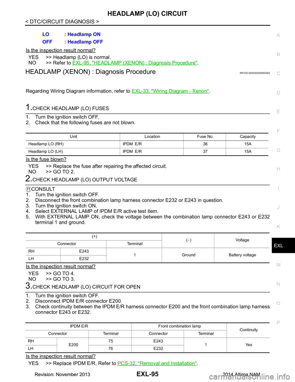
2.CHECK HEADLAMP (LO) OUTPUT VOLTAGE
CONSULT
1. Turn the ignition switch OFF.
2. Disconnect the front combination lamp harness connector E232 or E243 in question.
3. Turn the ignition switch ON.
4. Select EXTERNAL LAMP of IP DM E/R active test item.
5. With EXTERNAL LAMP ON, check the voltage betw een the combination lamp connector E243 or E232
terminal 1 and ground.
Is the inspection result normal?
YES >> GO TO 4.
NO >> GO TO 3.
3.CHECK HEADLAMP (LO) CIRCUIT FOR OPEN
1. Turn the ignition switch OFF.
2. Disconnect IPDM E/R connector E200.
3. Check continuity between the IPDM E/R harness c onnector E200 and the front combination lamp harness
connector E243 or E232.
Is the inspection result normal?
YES >> Replace IPDM E/R. Refer to PCS-32, "Removal and Installation".
LO : Headlamp ON
OFF : Headlamp OFF
Unit Location Fuse No. Capacity
Headlamp LO (RH) IPDM E/R 36 15A
Headlamp LO (L H) IPDM E/R 37 15A
(+)
(− )Voltage
Connector Terminal
RH E243 1 Ground Battery voltage
LH E232
IPDM E/R Front combination lamp Continuity
Connector Terminal Connector Terminal
RH E20075 E243
1Yes
LH 76 E232
Revision: November 20132014 Altima NAMRevision: November 20132014 Altima NAM
Page 2363 of 4801
XENON HEADLAMPEXL-97
< DTC/CIRCUIT DIAGNOSIS >
C
D E
F
G H
I
J
K
M A
B
EXL
N
O P
XENON HEADLAMP
DescriptionINFOID:0000000009463586
OPERATION
Refer to EXL-9, "HEADLAMP SYSTEM : System Description".
PRECAUTIONS FOR TROUBLE DIAGNOSIS
• Installation or removal of the connecto r must be done with the lighting switch OFF.
• When the lamp is illuminated (when the lighting switch is ON), do not touch the harness, HID control unit,
inside of the lamp, or the lamp metal parts.
• To check illumination, temporarily install lamp in the vehicle. Be sure to connect power at the vehicle-side
connector.
• If the malfunction can be traced directly to the electrical system, first check for items such as blown fuses
and fusible links, broken wires or loose connectors , pulled-out terminals, and improper connections.
• Do not work with wet hands.
• Using a tester for HID control unit circuit trouble diagnosis is prohibited.
• Disassembling the HID control unit or harnesses (bul b socket harness, ballast harness) is prohibited.
• Immediately after illumination, the light int ensity and color will fluctuate, this is normal.
• When the bulb has reached the end of its lifetime, the br ightness may drop significantly, it may flash repeat-
edly, or the light may turn a reddish color.
Diagnosis ProcedureINFOID:0000000009463587
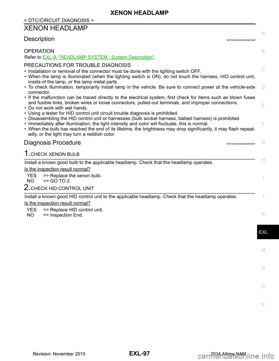
1.CHECK XENON BULB
Install a known good bulb to the applicable headlamp. Check that the headlamp operates.
Is the inspection result normal?
YES >> Replace the xenon bulb.
NO >> GO TO 2.
2.CHECK HID CONTROL UNIT
Install a known good HID control unit to the appl icable headlamp. Check that the headlamp operates.
Is the inspection result normal?
YES >> Replace HID control unit.
NO >> Inspection End.
Revision: November 20132014 Altima NAMRevision: November 20132014 Altima NAM