2014 NISSAN TEANA fuel pump
[x] Cancel search: fuel pumpPage 2490 of 4801
FL-10
< REMOVAL AND INSTALLATION >
FUEL TANK
FUEL TANK
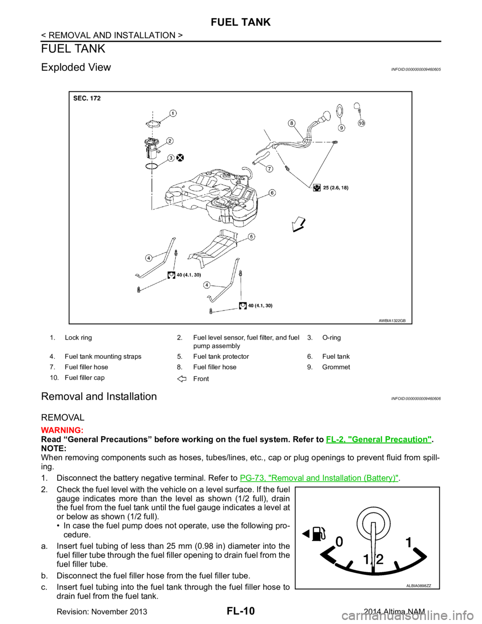
Exploded ViewINFOID:0000000009460605
Removal and InstallationINFOID:0000000009460606
REMOVAL
WARNING:
Read “General Precautions” before wo rking on the fuel system. Refer to FL-2, "General Precaution"
.
NOTE:
When removing components such as hoses, tubes/lines, etc. , cap or plug openings to prevent fluid from spill-
ing.
1. Disconnect the battery negative terminal. Refer to PG-73, "Removal and Installation (Battery)"
.
2. Check the fuel level with the vehicle on a level surface. If the fuel gauge indicates more than the level as shown (1/2 full), drain
the fuel from the fuel tank until the fuel gauge indicates a level at
or below as shown (1/2 full).
• In case the fuel pump does not operate, use the following pro- cedure.
a. Insert fuel tubing of less than 25 mm (0.98 in) diameter into the fuel filler tube through the fuel f iller opening to drain fuel from the
fuel filler tube.
b. Disconnect the fuel filler hose from the fuel filler tube.
c. Insert fuel tubing into the fuel tank through the fuel filler hose to drain fuel from the fuel tank.
1. Lock ring 2. Fuel level sensor, fuel filter, and fuel
pump assembly3. O-ring
4. Fuel tank mounting straps 5. Fuel tank protector 6. Fuel tank
7. Fuel filler hose 8. Fuel filler hose 9. Grommet
10. Fuel filler cap Front
AWBIA1322GB
ALBIA0898ZZ
Revision: November 20132014 Altima NAM
Page 2491 of 4801
FUEL TANKFL-11
< REMOVAL AND INSTALLATION >
C
D E
F
G H
I
J
K L
M A
FL
NP
O
• As a guide, if the fuel tank is full the fuel leve
l reaches or is less than the level on the fuel gauge as
shown, when approximately 34 (9 US gal, 7 1/2 Imp gal) of fuel is drained from a full fuel tank.
3. Open the fuel filler cap to release the pressure inside the fuel tank.
4. Release fuel pressure from fuel line. Refer to EC-182, "Work Procedure"
(QR25DE), EC-687, "Work Pro-
cedure" (VQ35DE).
5. Remove rear seat cushion. Refer to SE-36, "Removal and Installation - Seat Assembly"
.
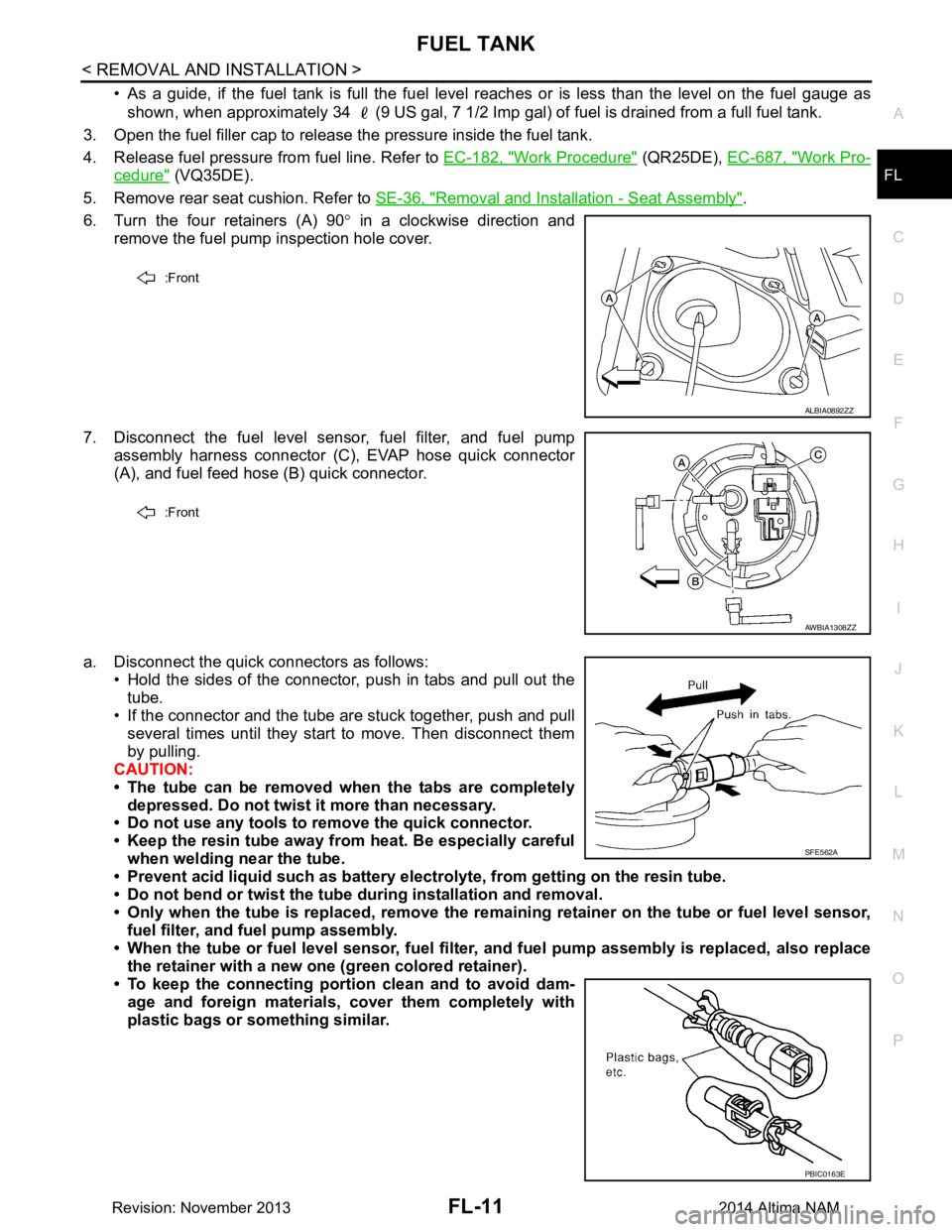
6. Turn the four retainers (A) 90 ° in a clockwise direction and
remove the fuel pump inspection hole cover.
7. Disconnect the fuel level sensor, fuel filter, and fuel pump assembly harness connector (C), EVAP hose quick connector
(A), and fuel feed hose (B) quick connector.
a. Disconnect the quick connectors as follows: • Hold the sides of the connector, push in tabs and pull out the
tube.
• If the connector and the tube are stuck together, push and pull
several times until they start to move. Then disconnect them
by pulling.
CAUTION:
• The tube can be removed when the tabs are completely depressed. Do not twist it more than necessary.
• Do not use any tools to remove the quick connector.
• Keep the resin tube away from heat. Be especially careful
when welding near the tube.
• Prevent acid liquid such as battery elect rolyte, from getting on the resin tube.
• Do not bend or twist the tube during installation and removal.
• Only when the tube is replaced, remove the remaining retainer on the tube or fuel level sensor,
fuel filter, and fuel pump assembly.
• When the tube or fuel level sen sor, fuel filter, and fuel pump assembly is replaced, also replace
the retainer with a new one (green colored retainer).
• To keep the connecting portio n clean and to avoid dam-
age and foreign materials, cover them completely with
plastic bags or something similar.
:Front
ALBIA0892ZZ
:Front
AWBIA1308ZZ
SFE562A
PBIC0163E
Revision: November 20132014 Altima NAM
Page 2492 of 4801
FL-12
< REMOVAL AND INSTALLATION >
FUEL TANK
8. Remove rear wheel and tire using power tool. Refer to WT-55, "Adjustment".
9. Remove rear brake pads. Refer to BR-38, "BRAKE PAD : Removal and Installation"
.
10. Remove rear torque members and rear disc brake rotor.
11. Disconnect rear parking brake shoe, and remove rear cables from toggle lever. Refer to PB-9, "Removal
and Installation".
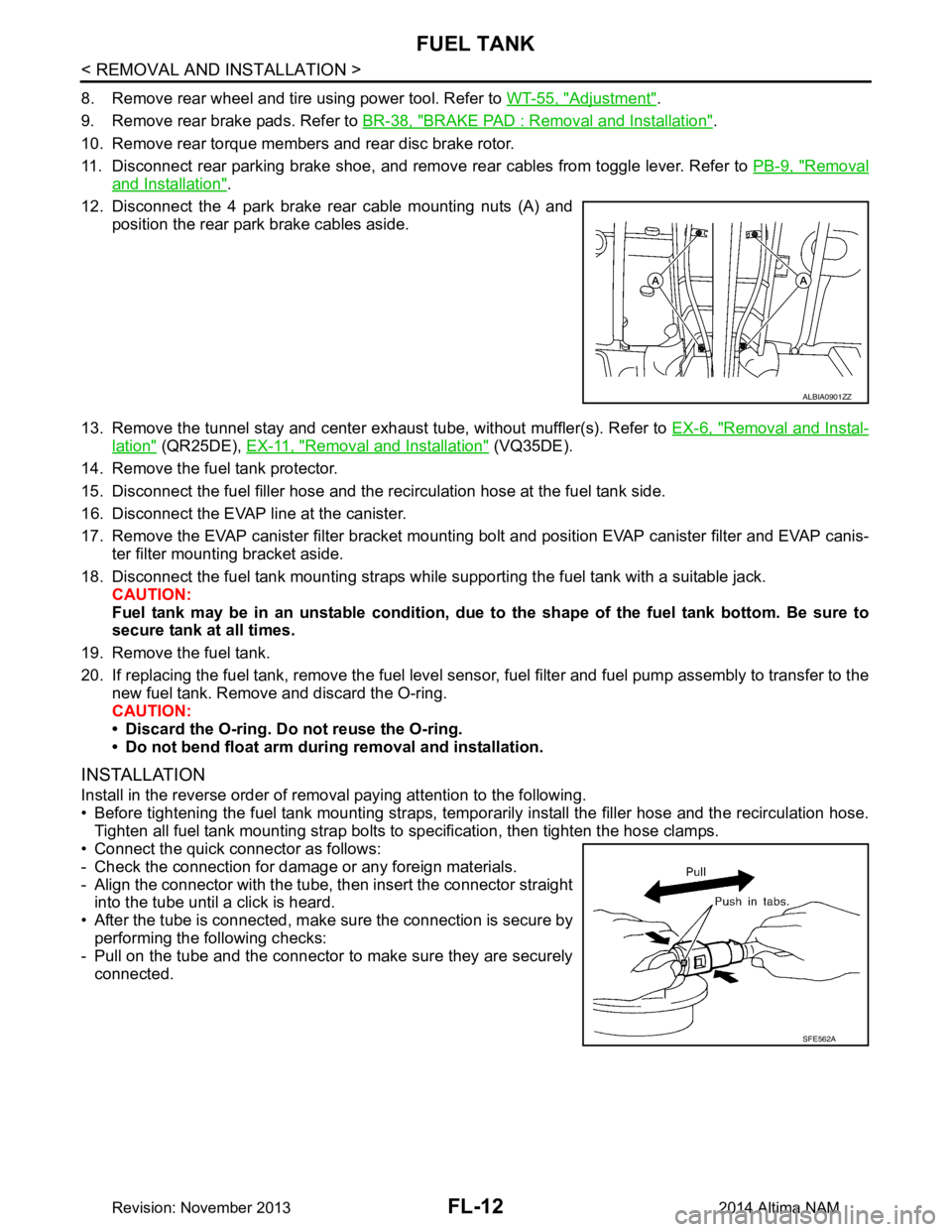
12. Disconnect the 4 park brake rear cable mounting nuts (A) and position the rear park brake cables aside.
13. Remove the tunnel stay and center exhaust tube, without muffler(s). Refer to EX-6, "Removal and Instal-
lation" (QR25DE), EX-11, "Removal and Installation" (VQ35DE).
14. Remove the fuel tank protector.
15. Disconnect the fuel filler hose and the recirculation hose at the fuel tank side.
16. Disconnect the EVAP line at the canister.
17. Remove the EVAP canister filter bracket mounti ng bolt and position EVAP canister filter and EVAP canis-
ter filter mounting bracket aside.
18. Disconnect the fuel tank mounting straps while supporting the fuel tank with a suitable jack. CAUTION:
Fuel tank may be in an unstable condition, due to the shape of the fuel tank bottom. Be sure to
secure tank at all times.
19. Remove the fuel tank.
20. If replacing the fuel tank, remove the fuel level sens or, fuel filter and fuel pump assembly to transfer to the
new fuel tank. Remove and discard the O-ring.
CAUTION:
• Discard the O-ring. Do not reuse the O-ring.
• Do not bend float arm during removal and installation.
INSTALLATION
Install in the reverse order of removal paying attention to the following.
• Before tightening the fuel tank mounting straps, tempor arily install the filler hose and the recirculation hose.
Tighten all fuel tank mounting strap bolts to specification, then tighten the hose clamps.
• Connect the quick connector as follows:
- Check the connection for damage or any foreign materials.
- Align the connector with the tube, then insert the connector straight into the tube until a click is heard.
• After the tube is connected, make sure the connection is secure by performing the following checks:
- Pull on the tube and the connector to make sure they are securely
connected.
ALBIA0901ZZ
SFE562A
Revision: November 20132014 Altima NAM
Page 2499 of 4801
FUEL LEVEL SENSOR UNITFL-19
< UNIT DISASSEMBLY AND ASSEMBLY >
C
D E
F
G H
I
J
K L
M A
FL
NP
O
UNIT DISASSEMBLY AND ASSEMBLY
FUEL LEVEL SENSOR UNIT
Disassembly and AssemblyINFOID:0000000009460617
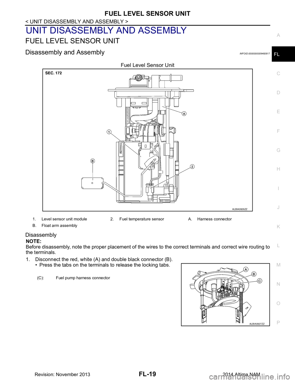
Fuel Level Sensor Unit
Disassembly
NOTE:
Before disassembly, note the proper placement of the wires to the correct terminals and correct wire routing to
the terminals.
1. Disconnect the red, white (A) and double black connector (B). • Press the tabs on the terminals to release the locking tabs.
ALBIA0926ZZ
1. Level sensor unit module 2. Fuel temperature sensor A. Harness connector
B. Float arm assembly
(C): Fuel pump harness connector
ALBIA0927ZZ
Revision: November 20132014 Altima NAM
Page 2500 of 4801
FL-20
< UNIT DISASSEMBLY AND ASSEMBLY >
FUEL LEVEL SENSOR UNIT
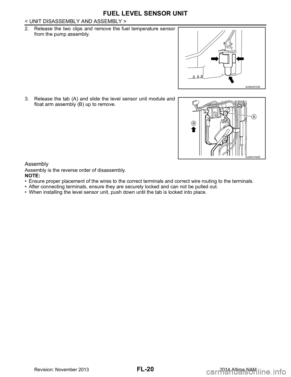
2. Release the two clips and remove the fuel temperature sensorfrom the pump assembly.
3. Release the tab (A) and slide the level sensor unit module and float arm assembly (B) up to remove.
Assembly
Assembly is the reverse order of disassembly.
NOTE:
• Ensure proper placement of the wires to the correct terminals and correct wire routing to the terminals.
• After connecting terminals, ensure they ar e securely locked and can not be pulled out.
• When installing the level sensor unit, push down until the tab is locked into place.
ALBIA0670ZZ
ALBIA0749ZZ
Revision: November 20132014 Altima NAM
Page 2542 of 4801

GI-14
< HOW TO USE THIS MANUAL >
ABBREVIATIONS
E
F
G
H
ABBREVIATION DESCRIPTION E/T Exhaust temperature
EBD Electric brake force distribution EC Engine control
ECL Engine coolant level
ECM Engine control module ECT Engine coolant temperature
ECV Electrical control valve
EEPROM Electrically erasable pr ogrammable read only memory
EFT Engine fuel temperature
EGR Exhaust gas recirculation
EGRT Exhaust gas recirculation temperature EGT Exhaust gas temperature
EOP Engine oil pressure EP Exhaust pressure
EPR Exhaust pressure regulator EPS Electronically cont rolled power steering
ESP Electronic stability program system
EVAP canister Evaporative emission canister EVSE Electric vehicle supply equipmentEXC Exhaust control
ABBREVIATION DESCRIPTION FC Fan control
FCW Forward collision warning FIC Fuel injector controlFP Fuel pump
FR Front
FRP Fuel rail pressure
FRT Fuel rail temperatureFTP Fuel tank pressure FTT Fuel tank temperature
ABBREVIATION DESCRIPTION GND GroundGPS Global positioning systemGST Generic scan tool
ABBREVIATION DESCRIPTION HBMC Hydraulic body-motion control systemHDD Hard disk drive
HO2S Heated oxygen sensor HOC Heated oxidation catalyst
HPCM Hybrid power train control module
Revision: November 20132014 Altima NAMRevision: November 20132014 Altima NAM
Page 2556 of 4801
GI-28
< PRECAUTION >
PRECAUTIONS
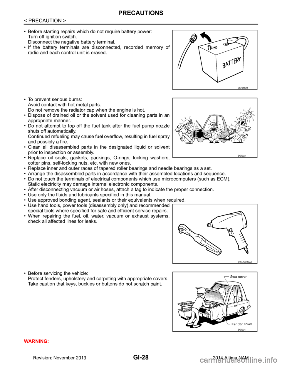
• Before starting repairs which do not require battery power:Turn off ignition switch.
Disconnect the negative battery terminal.
• If the battery terminals are disconnected, recorded memory of
radio and each control unit is erased.
• To prevent serious burns: Avoid contact with hot metal parts.
Do not remove the radiator cap when the engine is hot.
• Dispose of drained oil or the solvent used for cleaning parts in an
appropriate manner.
• Do not attempt to top off the fuel tank after the fuel pump nozzle
shuts off automatically.
Continued refueling may cause fuel overflow, resulting in fuel spray
and possibly a fire.
• Clean all disassembled parts in the designated liquid or solvent
prior to inspection or assembly.
• Replace oil seals, gaskets, packings, O-rings, locking washers, cotter pins, self-locking nuts, etc. with new ones.
• Replace inner and outer races of tapered roller bearings and needle bearings as a set.
• Arrange the disassembled parts in accordance with their assembled locations and sequence.
• Do not touch the terminals of electrical com ponents which use microcomputers (such as ECM).
Static electricity may damage internal electronic components.
• After disconnecting vacuum or air hoses, atta ch a tag to indicate the proper connection.
• Use only the fluids and lubricants specified in this manual.
• Use approved bonding agent, sealants or their equivalents when required.
• Use hand tools, power tools (disassembly only) and recommended special tools where specified for safe and efficient service repairs.
• When repairing the fuel, oil, water, vacuum or exhaust systems,
check all affected lines for leaks.
• Before servicing the vehicle: Protect fenders, upholstery and carpeting with appropriate covers.
Take caution that keys, buckles or buttons do not scratch paint.
WARNING:
SEF289H
SGI233
JPAIA0335ZZ
SGI234
Revision: November 20132014 Altima NAMRevision: November 20132014 Altima NAM
Page 2557 of 4801
PRECAUTIONSGI-29
< PRECAUTION >
C
D E
F
G H
I
J
K L
M B
GI
N
O P
To prevent ECM from storing the diagnostic trou ble codes, do not carelessly disconnect the harness
connectors which are related to the engine cont rol system and TCM (transmission control module)
system. The connectors should be disconnected only when working according to the WORK FLOW of
TROUBLE DIAGNOSES in EC and TM sections.
Three Way CatalystINFOID:0000000009462996
If a large amount of unburned fuel flows into the catalyst , the catalyst temperature will be excessively high. To
prevent this, follow the instructions.
• Use unleaded gasoline only. Leaded gasoline will seriously damage the three way catalyst.
• When checking for ignition spark or measuring engine compression, make tests quickly and only when nec- essary.
• Do not run engine when the fuel tank level is low, otherwise the engine may misfire, causing damage to the
catalyst.
Do not place the vehicle on flammable material. Keep flammable material off the exhaust pipe and the three
way catalyst.
Fuel (Regular Unleaded Ga soline Recommended) QR25DEINFOID:0000000009462997
Use unleaded regular gasoline with an octane rating of at least 87 AKI (Anti-Knock Index) number (Research
octane number 91). E-85 fuel (85% fuel ethanol, 15% unl eaded gasoline) may only be used in vehicles specif-
ically designed for E-85 fuel (i.e. Flexible Fuel Vehicle - FFV models).
CAUTION:
Do not use leaded gasoli ne. Using leaded gasoline will damage the three way catalyst. Do not use E-85
fuel (85% fuel ethanol, 15% unlead ed gasoline) unless the vehicle is specifically designed for E-85 fuel
(i.e. Flexible Fuel Vehicle - FFV models). Using a fu el other than that specified could adversely affect
the emission control devices and systems, and could also affect the warranty coverage validity.
Fuel (Regular Unleaded Gasoline Recommended) VQ35DEINFOID:0000000009462998
Use unleaded regular gasoline with an octane rating of at least 87 AKI (Anti-Knock Index) number (Research
octane number 91). E-85 fuel (85% fuel ethanol, 15% unl eaded gasoline) may only be used in vehicles specif-
ically designed for E-85 fuel (i.e. Flexible Fuel Vehicle - FFV models).
CAUTION:
Do not use leaded gasoli ne. Using leaded gasoline will damage the three way catalyst. Do not use E-85
fuel (85% fuel ethanol, 15% unlead ed gasoline) unless the vehicle is specifically designed for E-85 fuel
(i.e. Flexible Fuel Vehicle - FFV models). Using a fu el other than that specified could adversely affect
the emission control devices and systems, and could also affect the warranty coverage validity.
Multiport Fuel Injection System or Engine Control SystemINFOID:0000000009462999
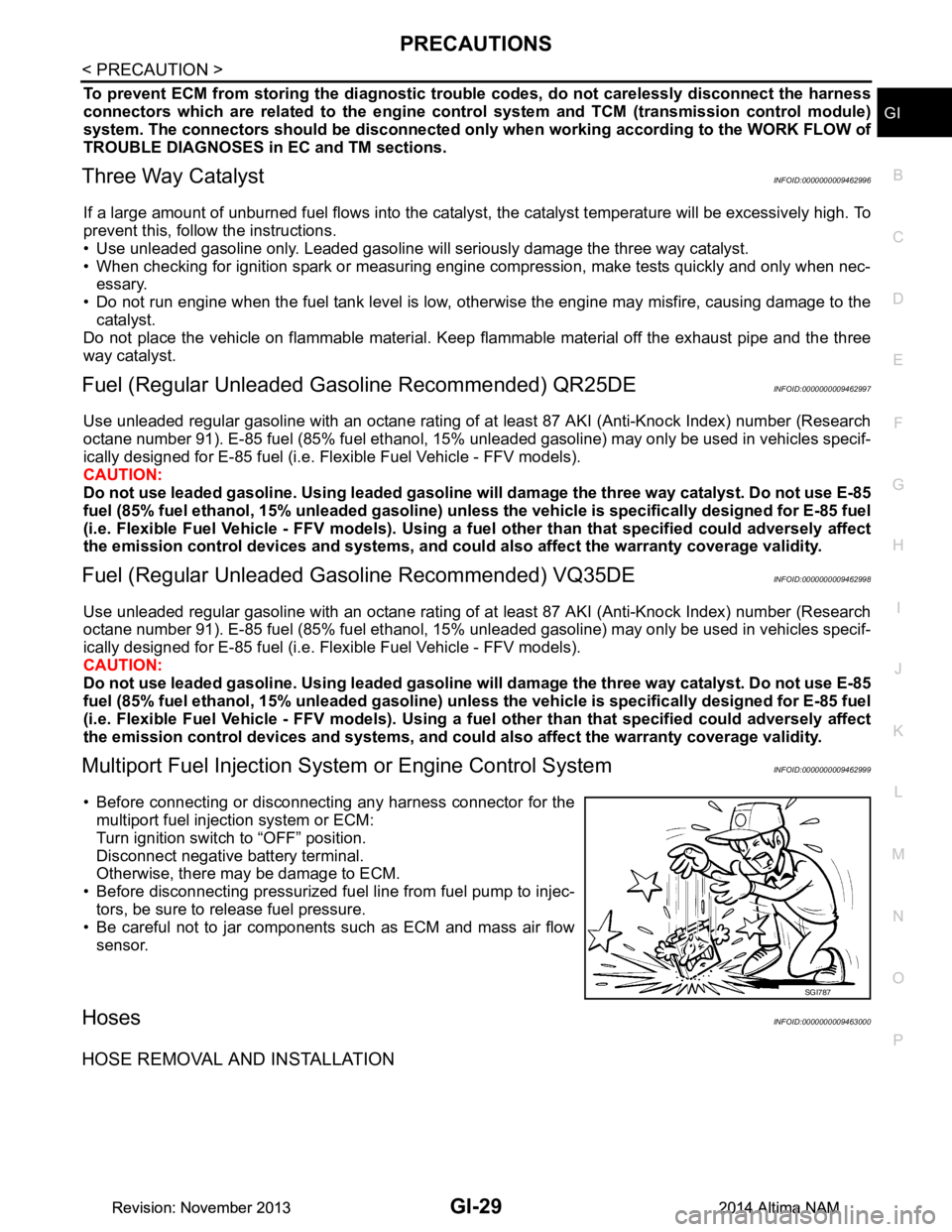
• Before connecting or disconnecti ng any harness connector for the
multiport fuel injection system or ECM:
Turn ignition switch to “OFF” position.
Disconnect negative battery terminal.
Otherwise, there may be damage to ECM.
• Before disconnecting pressurized fuel line from fuel pump to injec-
tors, be sure to release fuel pressure.
• Be careful not to jar components such as ECM and mass air flow sensor.
HosesINFOID:0000000009463000
HOSE REMOVAL AND INSTALLATION
SGI787
Revision: November 20132014 Altima NAMRevision: November 20132014 Altima NAM