2014 NISSAN TEANA fuel pump
[x] Cancel search: fuel pumpPage 1990 of 4801
![NISSAN TEANA 2014 Service Manual
EC-990
< SYMPTOM DIAGNOSIS >[VQ35DE]
ENGINE CONTROL SYSTEM SYMPTOMS
1 - 6: The numbers refer to the order of inspection.Va l v e
mecha-
nism Timing chain
55555 55 5 EM-182
Camshaft
EM-194
Intake NISSAN TEANA 2014 Service Manual
EC-990
< SYMPTOM DIAGNOSIS >[VQ35DE]
ENGINE CONTROL SYSTEM SYMPTOMS
1 - 6: The numbers refer to the order of inspection.Va l v e
mecha-
nism Timing chain
55555 55 5 EM-182
Camshaft
EM-194
Intake](/manual-img/5/57390/w960_57390-1989.png)
EC-990
< SYMPTOM DIAGNOSIS >[VQ35DE]
ENGINE CONTROL SYSTEM SYMPTOMS
1 - 6: The numbers refer to the order of inspection.Va l v e
mecha-
nism Timing chain
55555 55 5 EM-182
Camshaft
EM-194
Intake valve timing controlEM-172,
EM-173
Intake valve 3EM-210
Exhaust valve
Exhaust Exhaust manifold/Tube/Muffler/ Gasket 55555 55 5 EM-152
,
EM-153
,
EX-11
Three way catalyst
Lubrica-
tion Oil pan/Oil strainer/Oil pump/Oil
filter/Oil gallery/Oil cooler 55555 55 5 EM-156
,
LU-27
, LU-
29, LU-32
Oil level (Low)/Filthy oil LU-25
Cooling
Radiator/Hose/Radiator filler cap
55555 55 45 CO-40,
CO-51
Thermostat 5 CO-49
Water pumpCO-44
Water galleryCO-31
Cooling fan
5CO-42
Coolant level (Low)/Contaminat-
ed coolant CO-35
NVIS (NISSAN Vehicle Immobilizer System —
NATS) 11
SEC-11
SYMPTOM
Reference
page
HARD/NO START/RESTART (EXCP. HA)
ENGINE STALL
HESITATION/SURGING/FLAT SPOT
SPARK KNOCK/DETONATION
LACK OF POWER/POOR ACCELERATION
HIGH IDLE/LOW IDLE
ROUGH IDLE/HUNTING
IDLING VIBRATION
SLOW/NO RETURN TO IDLE
OVERHEATS/WATER TEMPERATURE HIGH
EXCESSIVE FUEL CONSUMPTION
EXCESSIVE OIL CONSUMPTION
BATTERY DEAD (UNDER CHARGE)
Warranty symptom code AA AB AC AD AE AF AG AH AJ AK AL AM HA
Revision: November 20132014 Altima NAMRevision: November 20132014 Altima NAM
Page 2140 of 4801
![NISSAN TEANA 2014 Service Manual
EM-142
< PERIODIC MAINTENANCE >[VQ35DE]
COMPRESSION PRESSURE
COMPRESSION PRESSURE
On-Vehicle ServiceINFOID:0000000009460536
CHECKING COMPRESSION PRESSURE
1. Run the engine until it reaches normal ope NISSAN TEANA 2014 Service Manual
EM-142
< PERIODIC MAINTENANCE >[VQ35DE]
COMPRESSION PRESSURE
COMPRESSION PRESSURE
On-Vehicle ServiceINFOID:0000000009460536
CHECKING COMPRESSION PRESSURE
1. Run the engine until it reaches normal ope](/manual-img/5/57390/w960_57390-2139.png)
EM-142
< PERIODIC MAINTENANCE >[VQ35DE]
COMPRESSION PRESSURE
COMPRESSION PRESSURE
On-Vehicle ServiceINFOID:0000000009460536
CHECKING COMPRESSION PRESSURE
1. Run the engine until it reaches normal operating temperature.
2. Turn the ignition switch to OFF.
3. Release fuel pressure and leave t he fuel pump electrically disconnected.
Refer to EC-687, "Work Procedure"
.
4. Remove all six spark plugs. Refer to EM-132, "Removal and Installation"
.
5. Install the compression tester with the adapter into the spark plug hole. • Use compression tester whose end (a) (rubber portion) is
smaller than 20 mm (0.79 in) in diameter. Otherwise, it may be
caught by cylinder head during removal.
6. Depress accelerator pedal fully to keep the electric throttle control actuator butterfly-valve wide open to
maximize air intake flow.
7. Crank the engine and record the highest gauge indication.
8. Repeat the measurement on each cylinder (steps 5 - 7). NOTE:
Always use a fully charged battery to obtain specified engine speed.
Unit: kPa (kg/cm2, psi)/rpm
9. If compression in one or more cylinders is low:
a. Pour a small amount of engine oil into cylinders through the spark plug holes.
b. Retest compression (steps 5 - 8).
• If adding oil helps raise compression pressure, then the piston rings may be worn or damaged. If so, replace piston rings after checking piston.
• If the pressure stays low, a valve may be sticking or is seating improperly. Inspect and repair the valve and/
or valve seat. Refer to EM-212, "Inspection After Disassembly"
. If the valve and/or valve seat is damaged
replace as necessary.
• If compression stays low in two or more cylinders that are next to each other:
- The cylinder head gasket may be leaking.
- Both cylinders may have valve component damage. Inspect and repair as necessary.
JPBIA0171ZZ
Standard Minimum Difference limit between cylinders
1,275 (13.0, 185)/300 981 (10.0, 142)/300 98 (1.0, 14)/300
Revision: November 20132014 Altima NAM
Page 2158 of 4801
![NISSAN TEANA 2014 Service Manual
EM-160
< REMOVAL AND INSTALLATION >[VQ35DE]
OIL PAN AND OIL STRAINER
4. Apply a bead of sealant to the cylinder block mating surface of
the upper oil pan to a limited portion as shown.
• Use Genui NISSAN TEANA 2014 Service Manual
EM-160
< REMOVAL AND INSTALLATION >[VQ35DE]
OIL PAN AND OIL STRAINER
4. Apply a bead of sealant to the cylinder block mating surface of
the upper oil pan to a limited portion as shown.
• Use Genui](/manual-img/5/57390/w960_57390-2157.png)
EM-160
< REMOVAL AND INSTALLATION >[VQ35DE]
OIL PAN AND OIL STRAINER
4. Apply a bead of sealant to the cylinder block mating surface of
the upper oil pan to a limited portion as shown.
• Use Genuine Silicone RTV Sealant, or equivalent. Refer to GI-
21, "Recommended Chemical Products and Sealants".
• Be sure the sealant is applied to a limited portion as shown, and the sealant is 4.5 - 5.5 mm (0.177 - 0.217 in) wide.
• Attaching should be done within 5 minutes after coating.
CAUTION:
The components must be instal led within 5 minutes of the
liquid gasket applicat ion. Then allow 30 minutes for the liq-
uid gasket to set before operating the engine.
5. Install new O-rings on the cylinder block and oil pump body. CAUTION:
Do not reuse O-rings.
6. Install the upper oil pan. • Tighten upper oil pan bolts in the order as shown.
• Wait at least 30 minutes before refilling the engine with oil.
7. Install the lower oil pan. Refer to EM-156, "Removal and Installation (Lower Oil Pan)"
.
8. Installation of the remaining components is in the reverse order of removal.
INSPECTION AFTER INSTALLATION
• Before starting engine, check oil/fluid levels incl uding engine coolant and engine oil. If less than required
quantity, fill to the specified level. Refer to MA-11, "FOR USA AND CANADA : Fluids and Lubricants"
.
• Use procedure below to check for fuel leakage.
• Turn ignition switch ON (with engine stopped). With fuel pressure applied to fuel piping, check for fuel leak- age at connection points.
• Start engine. With engine speed increased, che ck again for fuel leakage at connection points.
:Engine front
:Cut here
AWBIA1350ZZ
SEM159F
WBIA0327E
LBIA0359E
Revision: November 20132014 Altima NAM
Page 2481 of 4801

FL-1
ENGINE
C
D E
F
G H
I
J
K L
M
SECTION FL
A
FL
N
O P
CONTENTS
FUEL SYSTEM
PRECAUTION ................ ...............................2
PRECAUTIONS .............................................. .....2
Precaution for Supplemental Restraint System
(SRS) "AIR BAG" and "SEAT BELT PRE-TEN-
SIONER" ............................................................. ......
2
General Precaution ...................................................2
PREPARATION ............................................4
PREPARATION .............................................. .....4
Special Service Tool ........................................... ......4
Commercial Service Tool ..........................................4
PERIODIC MAINTENANCE ..........................5
FUEL SYSTEM ............................................... .....5
Inspection ............................................................ ......5
Quick Connector .......................................................5
REMOVAL AND INSTALLATION ................6
FUEL LEVEL SENSOR UNIT, FUEL FILTER
AND FUEL PUMP ASSEMBLY ..................... .....
6
Exploded View .................................................... ......6
Removal and Installation ...........................................6
Inspection ............................................................ ......9
FUEL TANK ........................................................10
Exploded View .................................................... ....10
Removal and Installation .........................................10
Inspection ............................................................ ....13
EVAP CANISTER ..............................................14
Exploded View .........................................................14
Removal and Installation .........................................14
Inspection ................................................................15
EVAP CANISTER FILTER ................................16
Exploded View .........................................................16
Removal and Installation .........................................16
EVAP CANISTER VENT CONTROL VALVE ...17
Exploded View .........................................................17
Removal and Installation .........................................17
EVAP CONTROL SYSTEM PRESSURE SEN-
SOR ...................................................................
18
Exploded View ..................................................... ....18
Removal and Installation .........................................18
UNIT DISASSEMBLY AND ASSEMBLY ....19
FUEL LEVEL SENSOR UNIT ...........................19
Disassembly and Assembly ................................. ....19
SERVICE DATA AND SPECIFICATIONS
(SDS) ............... .............................................
21
SERVICE DATA AND SPECIFICATIONS
(SDS) .................................................................
21
Fuel Tank ............................................................. ....21
Revision: November 20132014 Altima NAM
Page 2486 of 4801

FL-6
< REMOVAL AND INSTALLATION >
FUEL LEVEL SENSOR UNIT, FUEL FILTER AND FUEL PUMP ASSEMBLY
REMOVAL AND INSTALLATION
FUEL LEVEL SENSOR UNIT, FUEL FILTER AND FUEL PUMP ASSEMBLY
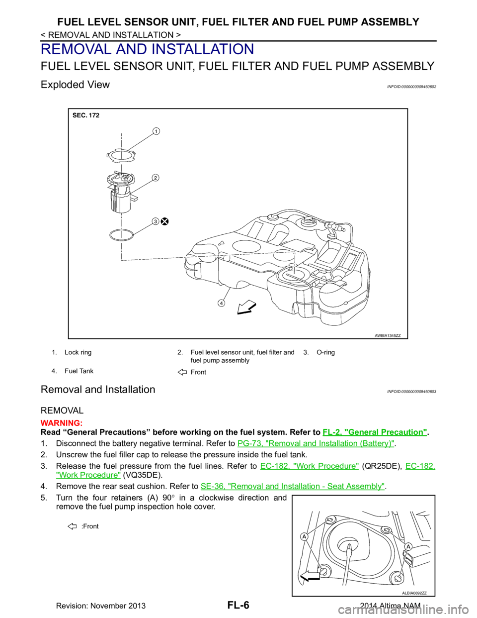
Exploded ViewINFOID:0000000009460602
Removal and InstallationINFOID:0000000009460603
REMOVAL
WARNING:
Read “General Precautions” before wo rking on the fuel system. Refer to FL-2, "General Precaution"
.
1. Disconnect the battery negative terminal. Refer to PG-73, "Removal and Installation (Battery)"
.
2. Unscrew the fuel filler cap to release the pressure inside the fuel tank.
3. Release the fuel pressure from the fuel lines. Refer to EC-182, "Work Procedure"
(QR25DE), EC-182,
"Work Procedure" (VQ35DE).
4. Remove the rear seat cushion. Refer to SE-36, "Removal and Installation - Seat Assembly"
.
5. Turn the four retainers (A) 90 ° in a clockwise direction and
remove the fuel pump inspection hole cover.
1. Lock ring 2. Fuel level sensor unit, fuel filter and
fuel pump assembly3. O-ring
4. Fuel Tank Front
AWBIA1345ZZ
:Front
ALBIA0892ZZ
Revision: November 20132014 Altima NAM
Page 2487 of 4801

FUEL LEVEL SENSOR UNIT, FUEL FILTER AND FUEL PUMP ASSEMBLYFL-7
< REMOVAL AND INSTALLATION >
C
D E
F
G H
I
J
K L
M A
FL
NP
O
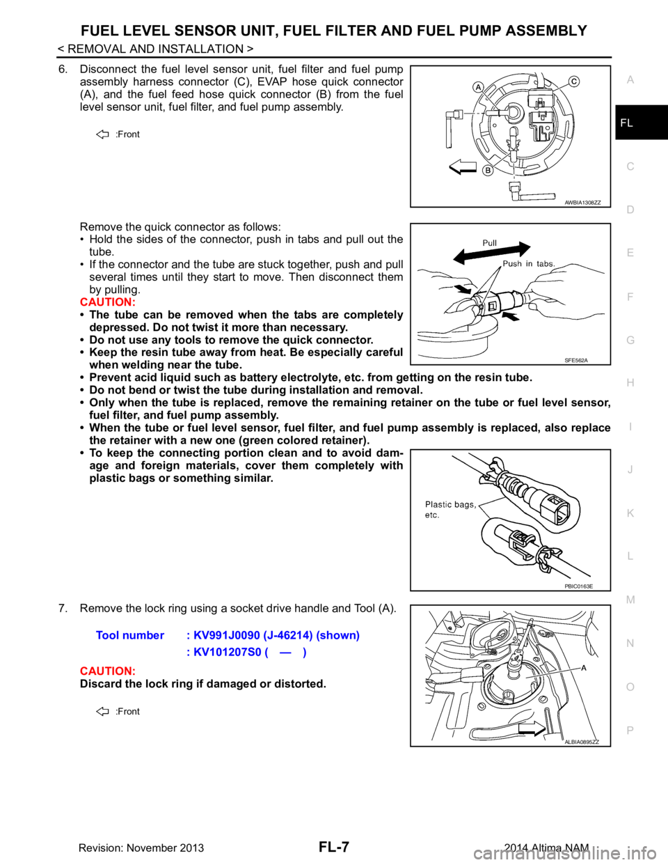
6. Disconnect the fuel level sensor unit, fuel filter and fuel pump
assembly harness connector (C), EVAP hose quick connector
(A), and the fuel feed hose quick connector (B) from the fuel
level sensor unit, fuel filter, and fuel pump assembly.
Remove the quick connector as follows:
• Hold the sides of the connector, push in tabs and pull out the
tube.
• If the connector and the tube are stuck together, push and pull several times until they start to move. Then disconnect them
by pulling.
CAUTION:
• The tube can be removed when the tabs are completely
depressed. Do not twist it more than necessary.
• Do not use any tools to remove the quick connector.
• Keep the resin tube away from heat. Be especially careful
when welding near the tube.
• Prevent acid liquid such as battery electroly te, etc. from getting on the resin tube.
• Do not bend or twist the tube during installation and removal.
• Only when the tube is replaced, remove the remaining retainer on the tube or fuel level sensor,
fuel filter, and fuel pump assembly.
• When the tube or fuel level sen sor, fuel filter, and fuel pump assembly is replaced, also replace
the retainer with a new one (green colored retainer).
• To keep the connecting portio n clean and to avoid dam-
age and foreign materials, cover them completely with
plastic bags or something similar.
7. Remove the lock ring using a socket drive handle and Tool (A). CAUTION:
Discard the lock ring if damaged or distorted.
:Front
AWBIA1308ZZ
SFE562A
PBIC0163E
Tool number : KV991J0090 (J-46214) (shown)
: KV101207S0 ( — )
:Front
ALBIA0895ZZ
Revision: November 20132014 Altima NAM
Page 2488 of 4801

FL-8
< REMOVAL AND INSTALLATION >
FUEL LEVEL SENSOR UNIT, FUEL FILTER AND FUEL PUMP ASSEMBLY
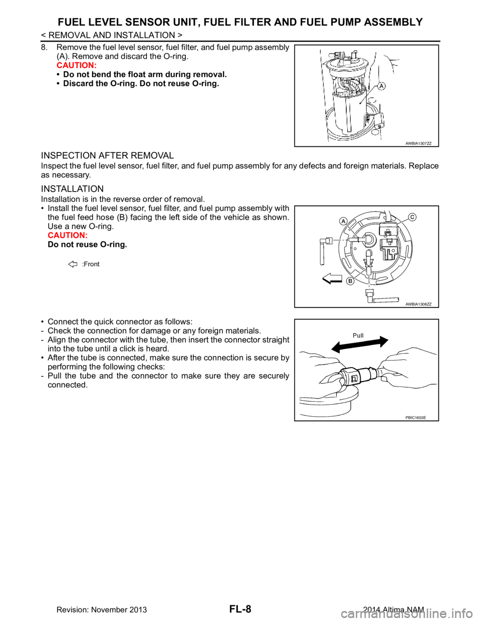
8. Remove the fuel level sensor, fuel filter, and fuel pump assembly
(A). Remove and discard the O-ring.
CAUTION:
• Do not bend the float arm during removal.
• Discard the O-ring. Do not reuse O-ring.
INSPECTION AFTER REMOVAL
Inspect the fuel level sensor, fuel filter, and fuel pump assembly for any defects and foreign materials. Replace
as necessary.
INSTALLATION
Installation is in the reverse order of removal.
• Install the fuel level sensor, fuel filter, and fuel pump assembly with the fuel feed hose (B) facing the left side of the vehicle as shown.
Use a new O-ring.
CAUTION:
Do not reuse O-ring.
• Connect the quick connector as follows:
- Check the connection for damage or any foreign materials.
- Align the connector with the tube, then insert the connector straight into the tube until a click is heard.
• After the tube is connected, make sure the connection is secure by performing the following checks:
- Pull the tube and the connector to make sure they are securely
connected.
AWBIA1307ZZ
:Front
AWBIA1308ZZ
PBIC1653E
Revision: November 20132014 Altima NAM
Page 2489 of 4801

FUEL LEVEL SENSOR UNIT, FUEL FILTER AND FUEL PUMP ASSEMBLYFL-9
< REMOVAL AND INSTALLATION >
C
D E
F
G H
I
J
K L
M A
FL
NP
O
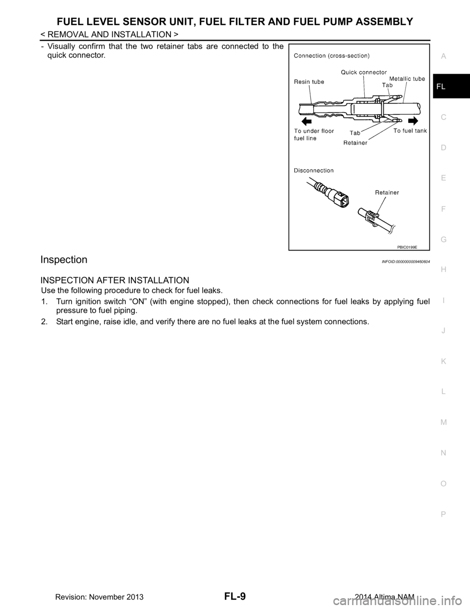
- Visually confirm that the two retainer tabs are connected to the
quick connector.
InspectionINFOID:0000000009460604
INSPECTION AFTER INSTALLATION
Use the following procedure to check for fuel leaks.
1. Turn ignition switch “ON” (with engine stopped), t hen check connections for fuel leaks by applying fuel
pressure to fuel piping.
2. Start engine, raise idle, and verify there are no fuel leaks at the fuel system connections.
PBIC0199E
Revision: November 20132014 Altima NAM