2014 NISSAN TEANA fuel pump
[x] Cancel search: fuel pumpPage 2982 of 4801
![NISSAN TEANA 2014 Service Manual
LAN
SYSTEMLAN-33
< SYSTEM DESCRIPTION > [CAN]
C
D E
F
G H
I
J
K L
B
A
O P
N
Engine status signal T R R R R
Fuel consumption monitor signal T R R
Fuel filler cap warning display signal T R
Malfunc NISSAN TEANA 2014 Service Manual
LAN
SYSTEMLAN-33
< SYSTEM DESCRIPTION > [CAN]
C
D E
F
G H
I
J
K L
B
A
O P
N
Engine status signal T R R R R
Fuel consumption monitor signal T R R
Fuel filler cap warning display signal T R
Malfunc](/manual-img/5/57390/w960_57390-2981.png)
LAN
SYSTEMLAN-33
< SYSTEM DESCRIPTION > [CAN]
C
D E
F
G H
I
J
K L
B
A
O P
N
Engine status signal T R R R R
Fuel consumption monitor signal T R R
Fuel filler cap warning display signal T R
Malfunctioning indicator lamp signal TR
RT
Oil pressure warning lamp signal T R
Power generation command value
signal TR
Target throttle position signal T R
Wide open throttle position signal T R
EPS operation signal R T
Hydraulic pump electric power steer-
ing warning lamp signal TR
Detention switch signal T R R
Front wiper stop position signal T R
High beam status signal R T
Hood switch signal T R
Interlock/PNP switch signal RT
TR R
Low beam status signal R T
Oil pressure switch signal RT
TR R
Push-button ignition switch status
signal TR
Rear window defogger control signal R T
Sleep ready signal T R
Starter relay status signal T R
Steering lock unit status signal T R
Steering lock relay signal RT
TR
Current gear position signal T R R
CVT position indicator signal T R R
Input shaft revolution signal R T R R
Manual mode indicator signal T R R
N range signal T R
Output shaft revolution signal R T R R
O/D OFF indicator signal
*1TR R
P range signal T R R
Shift position signal T R R
Brake fluid level signal T R
Distance to empty signal T R
Fuel filler cap warning reset signal R T
Fuel level low warning signal T R
Fuel level sensor signal R T Signal name
ECM
EPS
IPDM-E TCM
M&A
STRG AV
AV M
HVAC ABS
BCM
Revision: November 20132014 Altima NAMRevision: November 20132014 Altima NAM
Page 3262 of 4801

MWI
COMPONENT PARTSMWI-7
< SYSTEM DESCRIPTION >
C
D E
F
G H
I
J
K L
M B
A
O P
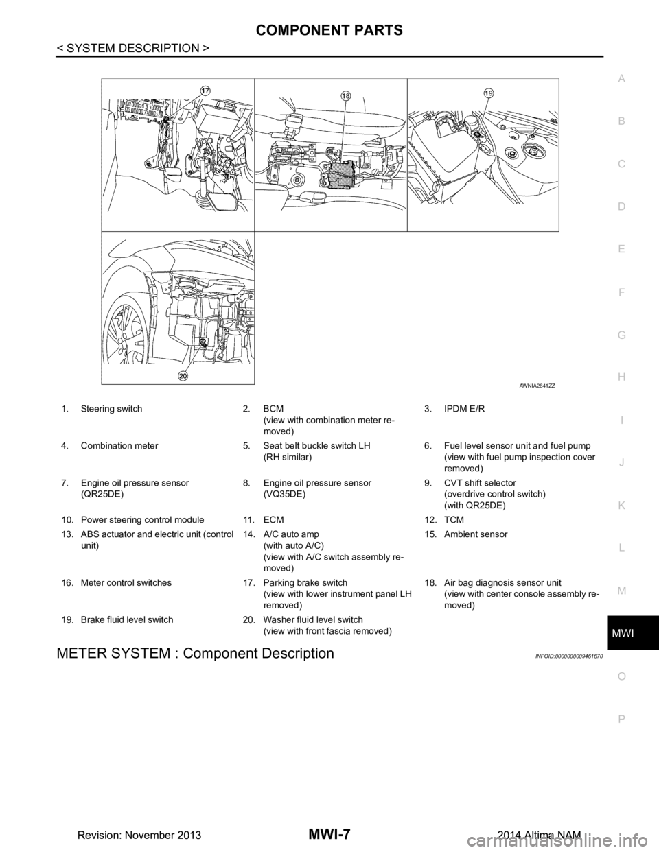
METER SYSTEM : Component DescriptionINFOID:0000000009461670
1. Steering switch 2. BCM (view with combination meter re-
moved) 3. IPDM E/R
4. Combination meter 5. Seat belt buckle switch LH (RH similar) 6. Fuel level sensor unit and fuel pump
(view with fuel pump inspection cover
removed)
7. Engine oil pressure sensor (QR25DE) 8. Engine oil pressure sensor
(VQ35DE) 9. CVT shift selector
(overdrive control switch)
(with QR25DE)
10. Power steering control module 11. ECM 12. TCM
13. ABS actuator and electric unit (control unit) 14. A/C auto amp
(with auto A/C)
(view with A/C swit ch assembly re-
moved) 15. Ambient sensor
16. Meter control switches 17. Parking brake switch (view with lower instrument panel LH
removed) 18. Air bag diagnosis sensor unit
(view with center console assembly re-
moved)
19. Brake fluid level switch 20. Washer fluid level switch (view with front fascia removed)
AWNIA2641ZZ
Revision: November 20132014 Altima NAMRevision: November 20132014 Altima NAM
Page 3316 of 4801

MWI
FUEL LEVEL SENSOR SIGNAL CIRCUITMWI-61
< DTC/CIRCUIT DIAGNOSIS >
C
D E
F
G H
I
J
K L
M B
A
O P
FUEL LEVEL SENSOR SIGNAL CIRCUIT
DescriptionINFOID:0000000009461718
The fuel level sensor unit and fuel pump detects the approx imate fuel level in the fuel tank and transmits the
fuel level signal to the combination meter.
Component Function CheckINFOID:0000000009461719
1.COMBINATION METER INPUT SIGNAL
1. Select METER/M&A on CONSULT.
2. Using FUEL METER of DATA MONITOR, compare the value of DATA MONITOR with fuel gauge pointer
of combination meter.
Does the data monitor value approxim ately match the fuel gauge indication?
YES >> Inspection End.
NO >> Replace combination meter. Refer to MWI-82, "Removal and Installation"
.
Diagnosis ProcedureINFOID:0000000009461720
Regarding Wiring Diagram information, refer to MWI-32, "Wiring Diagram".
1.CHECK HARNESS CONNECTOR
1. Turn ignition switch OFF.
2. Check combination meter and fuel level sensor uni t terminals (meter-side and harness-side) for poor con-
nection.
Is the inspection result normal?
YES >> GO TO 2.
NO >> Repair or replace terminals or connectors.
2.CHECK FUEL LEVEL SENSOR UNIT CIRCUIT
1. Disconnect combination meter harness connector M24 and fuel level sensor unit harness connector B42.
2. Check continuity between combination meter harne ss connector M24 and fuel level sensor unit and fuel
pump harness connector B42.
3. Check continuity between fuel level sens or unit and fuel pump harness connector and ground.
Is the inspection result normal?
YES >> GO TO 3.
Fuel gauge pointer Fuel tank volume [L]
(Approx.)
Full 67.6 3/4 52.6
1/2 37.6
1/4 22.5
Empty 0.0
Fuel level sensor unit and fuel pump Combination meter Continuity
Connector Terminal Connector Terminal
B42 5 M24 27 Yes
Connector Terminal GroundContinuity
B42 5 No
Revision: November 20132014 Altima NAMRevision: November 20132014 Altima NAM
Page 3317 of 4801

MWI-62
< DTC/CIRCUIT DIAGNOSIS >
FUEL LEVEL SENSOR SIGNAL CIRCUIT
NO >> Repair or replace harness or connectors.
3.CHECK FUEL LEVEL SENSOR UNIT GROUND CIRCUIT
1. Check continuity between combination meter harnes s connector M24 and fuel level sensor unit and fuel
pump harness connector B42.
2. Check continuity between fuel level sens or unit and fuel pump harness connector and ground.
Is the inspection result normal?
YES >> GO TO 4.
NO >> Repair or replace harness or connectors.
4.CHECK INSTALLATION CONDITION
Check fuel level sensor unit installation, and check whether the float arm interferes or binds with any of the
internal components in the fuel tank.
Is the inspection result normal?
YES >> Inspection End.
NO >> Install the fuel level sensor unit properly. Refer to FL-6, "Removal and Installation"
.
Component InspectionINFOID:0000000009461721
1.REMOVE FUEL LEVEL SENSOR UNIT
Remove the fuel level sensor unit. Refer to FL-6, "Removal and Installation"
.
>> GO TO 2
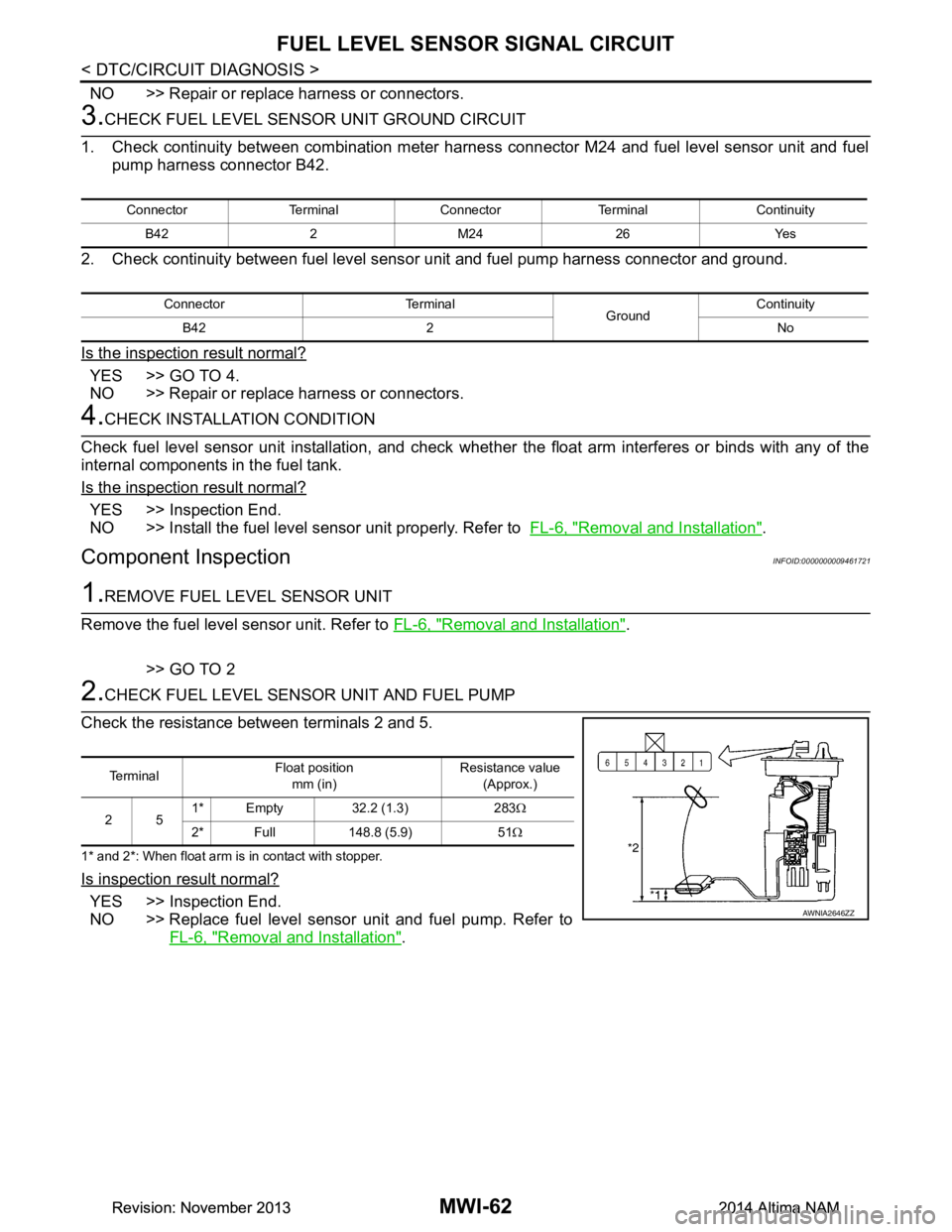
2.CHECK FUEL LEVEL SENSOR UNIT AND FUEL PUMP
Check the resistance between terminals 2 and 5.
1* and 2*: When float arm is in contact with stopper.
Is inspection result normal?
YES >> Inspection End.
NO >> Replace fuel level sensor unit and fuel pump. Refer to FL-6, "Removal and Installation"
.
Connector Terminal Connector Terminal Continuity
B42 2 M24 26 Yes
Connector Terminal GroundContinuity
B42 2 No
Te r m i n a l Float position
mm (in) Resistance value
(Approx.)
25 1* Empty 32.2 (1.3) 283
Ω
2* Full 148.8 (5.9) 51 Ω
AWNIA2646ZZ
Revision: November 20132014 Altima NAMRevision: November 20132014 Altima NAM
Page 3355 of 4801
![NISSAN TEANA 2014 Service Manual
PC S-6
< SYSTEM DESCRIPTION >[IPDM E/R]
SYSTEM
RELAY CONTROL SYSTEM : System Description
INFOID:0000000009461598
IPDM E/R activates the internal cont rol circuit to perform the relay ON-OFF control a NISSAN TEANA 2014 Service Manual
PC S-6
< SYSTEM DESCRIPTION >[IPDM E/R]
SYSTEM
RELAY CONTROL SYSTEM : System Description
INFOID:0000000009461598
IPDM E/R activates the internal cont rol circuit to perform the relay ON-OFF control a](/manual-img/5/57390/w960_57390-3354.png)
PC S-6
< SYSTEM DESCRIPTION >[IPDM E/R]
SYSTEM
RELAY CONTROL SYSTEM : System Description
INFOID:0000000009461598
IPDM E/R activates the internal cont rol circuit to perform the relay ON-OFF control according to the input sig-
nals from various sensors and the request signals received from control units via CAN communication.
CAUTION:
IPDM E/R integrated relays cannot be removed.
POWER CONSUMPTION CONTROL SYSTEM
Control relay Input/output T ransmit unitControl partReference
page
Front fog lamp relay Front fog lamp request signal BCM (CAN) Front fog lamp EXL-101
Headlamp high relay High beam request signal BCM (CAN) Headlamp highEXL-91
Headlamp low relay Low beam request signal BCM (CAN) Headlamp lowEXL-93
(halogen)
EXL-94
(xe-
non)
Tail lamp relay Position light request signal BCM (CAN) •Parking lamp
• Side marker lamp
• License plate lamp
•Tail lamp EXL-103
• Front wiper relay
• Front wiper high relay Front wiper request signal BCM (CAN)
Front wiperWW-48
Front wiper auto stop signal Front wiper motor
Cooling fan relay-1 Cooling fan request signal ECM Cooling fan EC-499
(QR25DE)
EC-953
(VQ35DE)
A/C relay A/C compressor request signal ECM (CAN) A/C compressor HAC-87
(automatic
air condi-
tioner)
HAC-151
(manual air
conditioner)
Ignition relay-1 Ignition switch ON signal BCM (CAN)
Ignition relay-1PCS-58
Vehicle speed signal Combination meter (CAN)
Push-button ignition switch Push-button ignition switch
Fuel pump relay Fuel pump request signal ECM Fuel pump EC-508
(QR25DE)
EC-965
(VQ35DE)
ECM relay ECM relay cont rol signal ECM ECM relay EC-203
(QR25DE)
EC-709
(VQ35DE)
Throttle contro l motor relay Throttle control
motor relay sig-
nal ECMThrottle control motor re-
lay EC-475
(QR25DE)
EC-933
(VQ35DE)
Starter relay Starter relay control signal BCM Starter motor PCS-12
Starter control relay
Revision: November 20132014 Altima NAMRevision: November 20132014 Altima NAM
Page 3364 of 4801
![NISSAN TEANA 2014 Service Manual
PCS
IPDM E/R (INTELLIGENT POWER DISTRIBUTION MODULE ENGINE ROOM)
PCS-15
< ECU DIAGNOSIS INFORMATION > [IPDM E/R]
C
D E
F
G H
I
J
K L
B
A
O P
N
7
(B) Ground Ground (Power) — Ignition switch ON 0V
NISSAN TEANA 2014 Service Manual
PCS
IPDM E/R (INTELLIGENT POWER DISTRIBUTION MODULE ENGINE ROOM)
PCS-15
< ECU DIAGNOSIS INFORMATION > [IPDM E/R]
C
D E
F
G H
I
J
K L
B
A
O P
N
7
(B) Ground Ground (Power) — Ignition switch ON 0V](/manual-img/5/57390/w960_57390-3363.png)
PCS
IPDM E/R (INTELLIGENT POWER DISTRIBUTION MODULE ENGINE ROOM)
PCS-15
< ECU DIAGNOSIS INFORMATION > [IPDM E/R]
C
D E
F
G H
I
J
K L
B
A
O P
N
7
(B) Ground Ground (Power) — Ignition switch ON 0V
9
(SB) Ground Tail RH Output Ignition
switch ON Lighting switch OFF 0V
Lighting switch 1ST Battery voltage
10
(V) Ground Tail LH Output Ignition
switch ON Lighting switch OFF 0V
Lighting switch 1ST Battery voltage
11
(Y) Ground Front wiper LO Output Ignition
switch ON Front wiper switch OFF 0V
Front wiper switch LO Battery voltage
13
(LG) Ground ECM battery Output Ignition switch OFF 0V
Ignition switch ON Battery voltage
14
(Y) Ground Daytime running lamps Output Ignition switch OFF Battery voltage
15
(R) Ground Fuel pump Output Approximately 1 second or more after
turning the ignition switch ON 0V
• Approximately 1 second after turning the ignition switch ON
• Engine running Battery voltage
18
(L) Ground Front wiper HI Output Ignition
switch ON Front wiper switch OFF 0V
Front wiper switch HI Battery voltage
19
(BR) Ground Power steering control unit Output Ignition switch OFF 0V
Ignition switch ON Battery voltage
21
(L) Ground ECM ignition switch Output Ignition switch OFF 0V
Ignition switch ON Battery voltage
22
(W) Ground Horn relay Input The horn is deactivated Battery voltage
The horn is activated 0V
23
(V) Ground Horn switch Input The horn is deactivated Battery voltage
The horn is activated 0V
27
(BG) Ground Fan motor relay mid Input Ignition switch OFF 0V
Ignition switch ON 0.7V
28
(P) —CAN-L
Input/
Output ——
29
(L) —CAN-H Input/
Output ——
31
(Y) Ground Detent switch Input Ignition
switch ON Press the CVT selector
button (CVT selector lever
P) Battery voltage
• CVT selector lever in any position other than
P
• Release the CVT selec- tor button (CVT selector
lever P) 0V
33
(R) Ground Starter control Input
Ignition
switch ON CVT selector lever in any
position other than P or N 0V
CVT selector lever P or N Battery voltage
34
(SB) Ground Wiper autostop Input Ignition
switch ON Front wiper stop position 0V
Any position other than
front wiper stop position Battery voltage
Te r m i n a l N o .
(Wire color) Description
ConditionVa l u e
(Approx.)
Signal name Input/
Output
+ −
Revision: November 20132014 Altima NAMRevision: November 20132014 Altima NAM
Page 3366 of 4801
![NISSAN TEANA 2014 Service Manual
PCS
IPDM E/R (INTELLIGENT POWER DISTRIBUTION MODULE ENGINE ROOM)
PCS-17
< ECU DIAGNOSIS INFORMATION > [IPDM E/R]
C
D E
F
G H
I
J
K L
B
A
O P
N
552
(W)
Ground Ignition coil Output Ignition switch OF NISSAN TEANA 2014 Service Manual
PCS
IPDM E/R (INTELLIGENT POWER DISTRIBUTION MODULE ENGINE ROOM)
PCS-17
< ECU DIAGNOSIS INFORMATION > [IPDM E/R]
C
D E
F
G H
I
J
K L
B
A
O P
N
552
(W)
Ground Ignition coil Output Ignition switch OF](/manual-img/5/57390/w960_57390-3365.png)
PCS
IPDM E/R (INTELLIGENT POWER DISTRIBUTION MODULE ENGINE ROOM)
PCS-17
< ECU DIAGNOSIS INFORMATION > [IPDM E/R]
C
D E
F
G H
I
J
K L
B
A
O P
N
552
(W)
Ground Ignition coil Output Ignition switch OFF
(For a few seconds after turning ignition
switch OFF) 0V
55
3
(G) • Ignition switch ON
• Ignition switch OFF
(More than a few seconds after turn-
ing ignition switch OFF) Battery voltage
56
(SB) Ground A/C compressor Output
Engine
running A/C compressor OFF 0V
A/C compressor ON
(A/C compressor is oper-
ating) Battery voltage
57
(R) Ground Electronic throttle control Output Ignition switch OFF
(For a few seconds after turning ignition
switch OFF) 0V
• Ignition switch ON
• Ignition switch OFF (More than a few seconds after turn-
ing ignition switch OFF) Battery voltage
58
(SB) Ground ECM battery Output Ignition switch OFF Battery voltage
59
(L) Ground Engine solenoid Output Ignition switch OFF
(For a few seconds after turning ignition
switch OFF) 0V
• Ignition switch ON
• Ignition switch OFF (More than a few seconds after turn-
ing ignition switch OFF) Battery voltage
60
(Y) Ground Injector #2 Output Ignition switch OFF 0V
Ignition switch ON Battery voltage
61
(Y) Ground
Transmission control mod-
ule OutputIgnition switch OFF 0V
Ignition switch ON Battery voltage
65
2
(BR) Ground Throttle control motor re-
lay OutputIgnition switch ON
→ OFF 0 -1.0V
↓
Battery voltage ↓
0V
65
3
(L) Ignition switch ON 0 - 1.0V
66
(LG) Ground N/P switch Input Ignition
switch ON CVT selector lever in P or
N position Battery voltage
CVT selector lever in any
position other than P or N
position 0V
69
(V) Ground Fuel pump relay Output • Approximately 1 second after turning
the ignition switch ON
• Engine running 0 - 1.0V
Approximately 1 second or more after
turning the ignition switch ON Battery voltage
Te r m i n a l N o .
(Wire color) Description
ConditionVa l u e
(Approx.)
Signal name Input/
Output
+ −
Revision: November 20132014 Altima NAMRevision: November 20132014 Altima NAM
Page 3484 of 4801

PG-52
< DTC/CIRCUIT DIAGNOSIS >
HARNESS
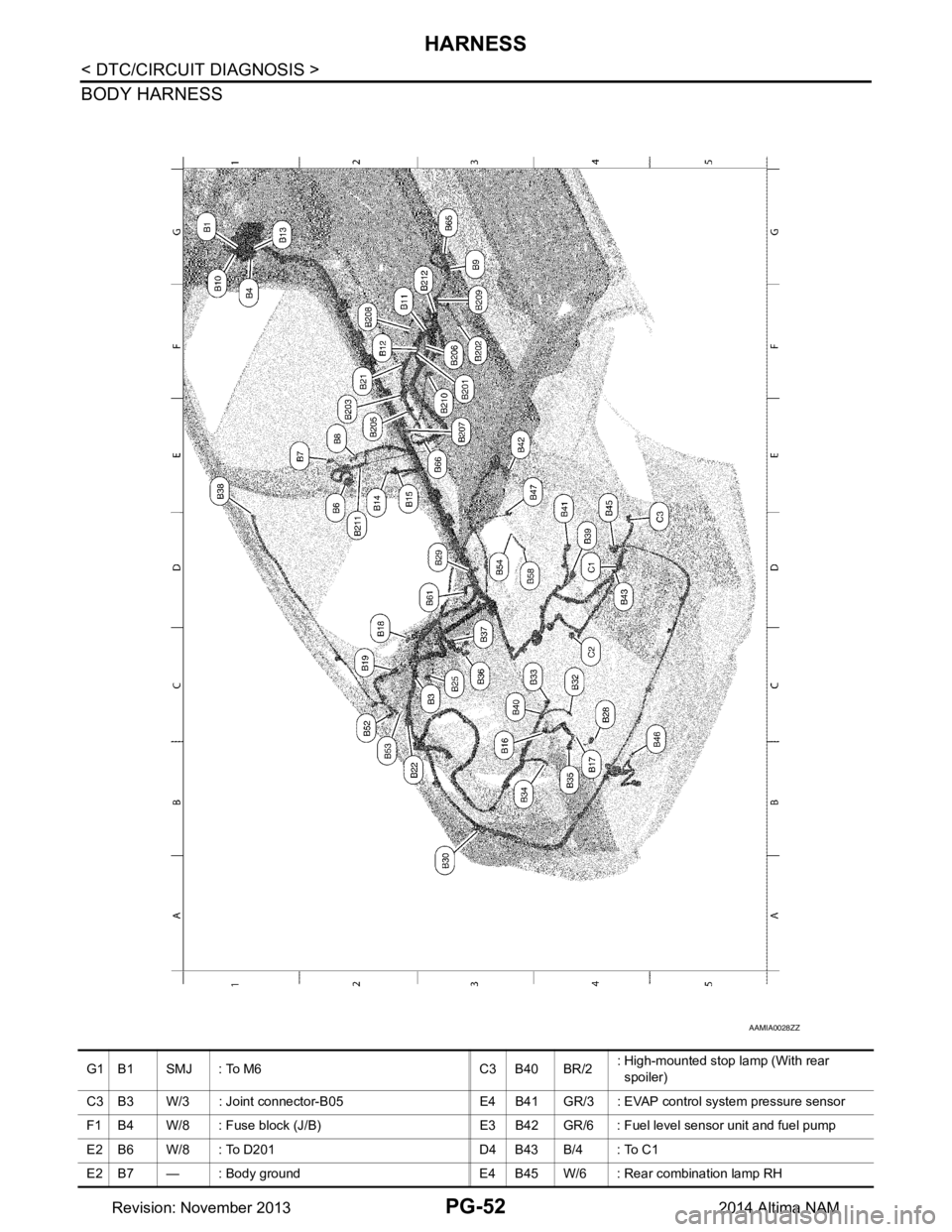
BODY HARNESS
AAMIA0028ZZ
G1 B1 SMJ : To M6 C3 B40 BR/2: High-mounted stop lamp (With rear
spoiler)
C3 B3 W/3 : Joint connector-B05 E4 B41 GR/3 : EVAP control system pressure sensor
F1 B4 W/8 : Fuse block (J/B) E3 B42 GR/6 : Fuel level sensor unit and fuel pump
E2 B6 W/8 : To D201 D4 B43 B/4 : To C1
E2 B7 — : Body ground E4 B45 W/6 : Rear combination lamp RH
Revision: November 20132014 Altima NAM