2014 MERCEDES-BENZ B-CLASS SPORTS trunk
[x] Cancel search: trunkPage 20 of 360
Labeling (overview)
........................329
Load bearing index (definition) ......335
Load index ..................................... 332
Load index (definition) ...................334
M+S tires ....................................... 314
Maximum loaded vehicle weight
(definition) ..................................... 334
Maximum loa donatire (definition) 334
Maximum permissible tire
pressure (definition) ....................... 334
Maximum tire loa d......................... 327
Maximum tire loa d(definition) .......334
MOExtended tires ..........................314
Optional equipment weight
(definition) ..................................... 335
PSI (pounds per square inch)
(definition) ..................................... 334
Replacing ....................................... 336
Service life ..................................... 314
Sidewall (definition) .......................335
Speed rating (definition) ................334
Storing ........................................... 336
Structure and characteristics
(definition) ..................................... 333
Summer tires ......................... 160, 314
Temperature .................................. 329
TIN (Tire Identification Number)
(definition) ..................................... 335
Tire bea d(definition) ...................... 335
Tire pressure (definition) ................335
Tire pressure s(recommended )...... 333
Tire size (data) ............................... 340
Tire size designation, load-bearing
capacity, spee drating .................... 330
Tire tread ....................................... 313
Tire tread (definition) .....................335
Total loa dlimit (definition) .............335
Traction ......................................... 328
Traction (definition) .......................335
Trea dwear ..................................... 328
Uniform Tire Quality Grading
Standard s...................................... 328
Uniform Tire Quality Grading
Standard s(definition) .................... 333
Unladen weight (definition) ............334
Wea rindicato r(definition) .............335
Whee lrim (definition ).................... 333
see Flat tire Top Tether
............................................ 60
Towing Important safety guidelines ...........305
Installing the towing eye. ...............306
Removing the towing eye. ..............306
Towing away
With both axle sonthe ground .......307
With front axle raised ..................... 307
Tow-starting
Emergency engine starting ............308
Important safety notes ..................305
Installing the towing eye. ...............306
Removing the towing eye. ..............306
Transmission
see Automatic transmission
Transmission position display .........144
Transporting the vehicle ..................307
Trim pieces (cleaning instructions) .290
Trip computer (on-board computer) 194
Trip odometer Calling up ....................................... 193
Resetting (on-board computer) ......195
Trunk
see Tailgate
Turn signals
Changing bulbs (front) ...................114
Changing bulbs (rear) ....................115
Display message ............................ 220
Switching on/off ........................... 106
Type identification plate
see Vehicle identification plate U
Unlocking Emergency unlocking .......................81
From insid ethe vehicle (central
unlocking button) ............................. 80 V
Vanity mirror (in the sun visor) ........263
Vehicle Correct use ...................................... 25
Data acquisition ............................... 26
Equipment ....................................... 22
Individua lsettings .......................... 202
Limited Warranty ............................. 2618
Index
Page 256 of 360
X
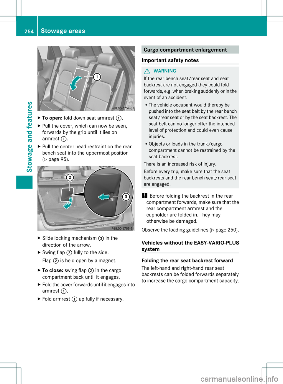
To open: foldd owns eata rmrest 001A.
X Pullt he cover, which can now be seen,
forwards by the grip until it lieson
armrest 001A.
X Pullt he center headr estraint on the rear
bench seat into the uppermost position
(Y page9 5). X
Slide locking mechanism 0023in the
direction of the arrow.
X Swing flap 0010fullytot he side.
Flap 0010is held open by amagnet.
X To close: swing flap 0010in the cargo
compartment back until it engages.
X Fold the cover forwards until it engages into
armrest 001A.
X Fold armrest 001Aup full yifnecessary. Cargo compartment enlargement
Important safety notes G
WARNING
If the rear bench seat/rea rseat and seat
backrest are not engaged they coul dfold
forwards, e.g. when braking suddenly or in the
event of an accident.
R The vehicl eoccupant would thereby be
pushed into the seat belt by the rear bench
seat/rea rseat or by the seat backrest. The
seat belt can no longer offer the intended
level of protection and could even cause
injuries.
R Objects or loads in the trunk/cargo
compartment cannot be restrained by the
seat backrest.
There is an increased risk of injury.
Befor eevery trip, make sure that the seat
backrests and the rear bench seat/rear seat
are engaged.
! Befor efolding the backrest in the rear
compartment forwards, make sure that the
rear compartment armrest and the
cupholder are folded in. They may
otherwise be damaged.
Observe the loading guidelines (Y page 250).
Vehicles without the EASY-VARIO-PLUS
system Folding the rear seat backrest forward
The left-hand and right-hand rear seat
backrests can be folded forwards separately
to increase the cargo compartment capacity.254
Stowage areasStowage and features
Page 258 of 360
Folding th
erears eat backres tback X
Mov ethe driver' sorfront-pa ssenger seat
forward if necessary.
! Mak esure that th eseat belt does not
become trapped when foldin gthe rear seat
backres tback .Otherwise, it could be
damaged.
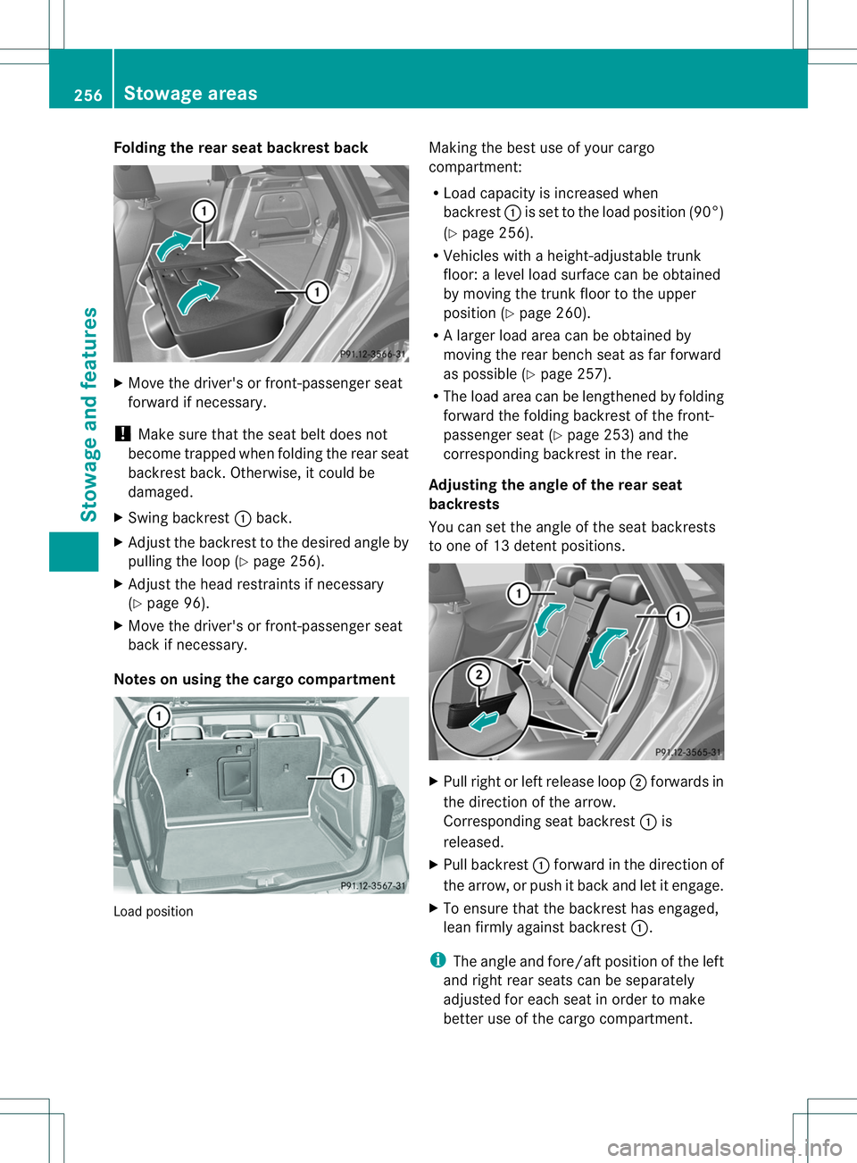
X Swing backrest 001Aback.
X Adjust the backrest to the desired angle by
pulling the loop (Y page 256).
X Adjust the head restraints if necessary
(Y page 96).
X Move the driver's or front-passenge rseat
back if necessary.
Notes on using the cargo compartment Load position Making the best use of your cargo
compartment:
R
Load capacity is increased when
backrest 001Ais set to the load position (90°)
(Y page 256).
R Vehicles with aheight-adjustable trunk
floor: alevel load surface can be obtained
by movin gthe trun kfloor to the upper
position (Y page 260).
R Al arge rload area can be obtained by
moving the rear bench seat as far forward
as possible (Y page 257).
R The load area can be lengthened by folding
forward the folding backrest of the front-
passenger seat (Y page 253) and the
corresponding backrest in the rear.
Adjusting the angle of the rear seat
backrests
You can set the angle of the seat backrests
to one of 13 detent positions. X
Pull right or left release loop 0010forwards in
the direction of the arrow.
Corresponding seat backrest 001Ais
released.
X Pull backrest 001Aforward in the direction of
the arrow, or push it back and let it engage.
X To ensure that the backrest has engaged,
lean firmly against backrest 001A.
i The angle and fore/aft position of the left
and right rear seats can be separately
adjusted for each seat in order to make
better use of the cargo compartment. 256
Stowage areasStowage and features
Page 262 of 360
X
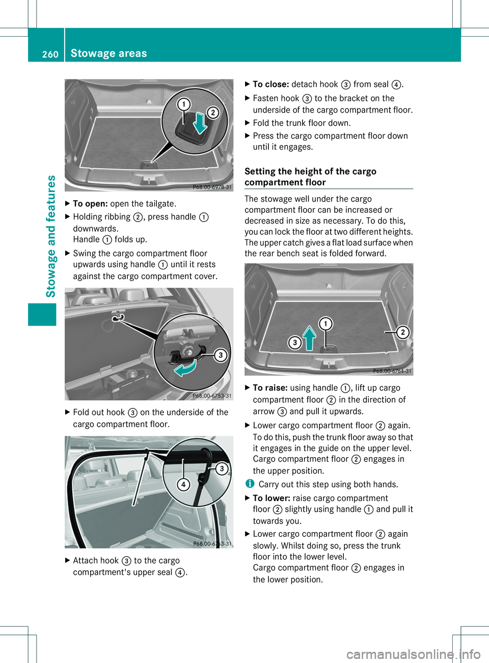
To open: open the tailgate.
X Holding ribbing 0010,press handle 001A
downwards.
Handle 001Afolds up.
X Swing the cargo compartment floor
upwards using handle 001Aunti litr ests
against the cargo compartment cover. X
Fol do ut hook 0023on th eunderside of the
cargo compartment floor. X
Attach hook 0023to the cargo
compartment's upper seal 0021.X
To close: detach hook 0023from seal 0021.
X Fasten hook 0023to the bracket on the
underside of the cargo compartment floor.
X Fold the trunk floor down.
X Press the cargo compartment floor down
until it engages.
Setting the height of the cargo
compartment floor The stowage well under the cargo
compartment floor can be increased or
decreased in size as necessary. To do this,
you can lock the floor at two different heights.
The upper catchg
ivesaflat load surface when
the rear bench seat is folded forward. X
To raise: using handle 001A,lift up cargo
compartment floor 0010in the direction of
arrow 0023and pull it upwards.
X Lower cargo compartment floor 0010again.
To do this, push the trunk floor away so that
it engages in the guide on the upper level.
Cargo compartment floor 0010engages in
the upper position.
i Carry out this step using both hands.
X To lower: raise cargo compartment
floor 0010slightly using handle 001Aand pull it
towards you.
X Lower cargo compartment floor 0010again
slowly. Whilst doing so, press the trunk
floor into the lower level.
Cargo compartment floor 0010engages in
the lower position. 260
Stowage areasStowage and features
Page 340 of 360
The followin
gmust be observe dwhen
raisin gthe vehicle:
R to raise the vehicle, only use the vehicle-
specific jack that has been tested and
approved by Mercedes-Benz. If used
incorrectly ,the jack coul dtip over with the
vehicle raised.
R the jack is designed only to raise and hold
the vehicle for ashort time while awheel
is being changed .Itisnot suited for
performing maintenance work under the
vehicle.
R avoid changing the wheel on uphilla nd
downhill slopes.
R before raising the vehicle, secure it from
rolling awaybya pplying the parking brake
and inserting wheel chocks. Never
disengage the parking brake while the
vehicle is raised.
R the jack must be placed on afirm, flat and
non-slip surface. On aloose surface, a
large, load-bearing underlay must be used.
On aslippery surface, anon-slip underlay
must be used, e.g. rubber mats.
R do not use wooden blocks or similar
objects as ajack underlay.O therwise, the
jack will not be able to achieve its load-
bearing capacity du etothe restricted
height.
R make sure tha tthe distance between the
underside of the tires and the ground does
not exceed 1.2 in (3 cm).
R never place your hands and feet under the
raised vehicle.
R never lie under the raised vehicle.
R never start the engine when the vehicle is
raised.
R never open or close adoor or the trunk lid
when the vehicle is raised.
R make sure that no persons are present in
the vehicle when the vehicle is raised.
! The jack is designed exclusively for
jackingupt he vehicle at the jackingp oints.
Otherwise, your vehicle could be damaged. X
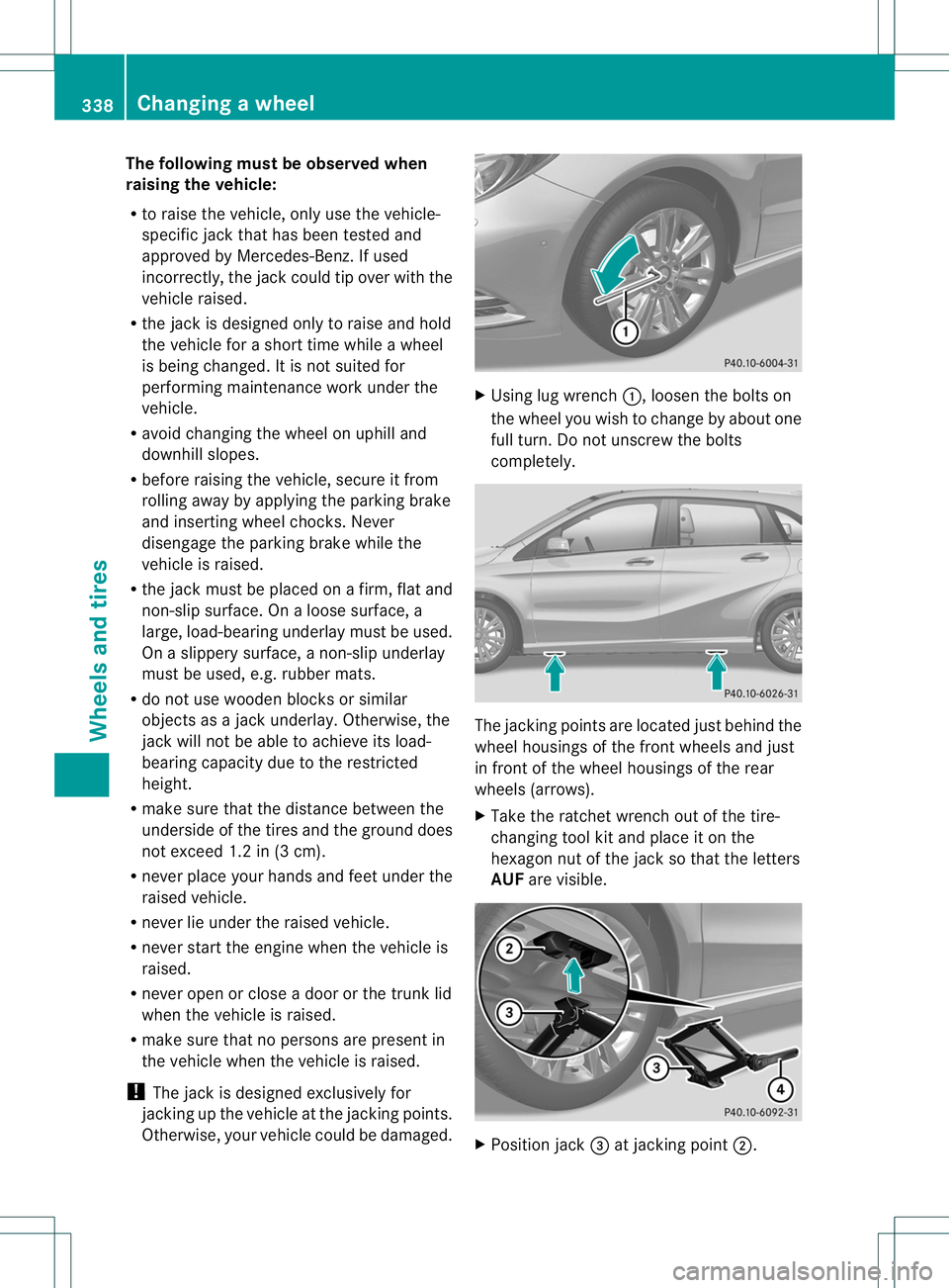
Using lug wrench 001A,loosen the bolts on
the wheel you wish to change by about one
full turn. Do not unscrew the bolts
completely. The jackingp
oints are located just behind the
wheel housings of the front wheels and just
in front of the wheel housings of the rear
wheels (arrows).
X Take the ratchet wrench out of the tire-
changing tool kit and place it on the
hexagon nut of the jack so that the letters
AUF are visible. X
Position jack 0023at jackingp oint0010. 338
Changing
awheelWheels and tires
Page 345 of 360
monitor cannot function reliably. Only
restart the tire pressure loss warning
system/the tire pressure monitor when the
damaged whee lhas been replaced with a
new wheel.
Vehicles with tire pressure monitor:
after mounting an emergency spare wheel,
the system may still display the tire
pressure of the removed whee lfor afew
minutes. The value displayed for the
mounted emergenc yspare wheel is not the
same as the current tire pressure of the
emergenc yspare wheel.
An emergenc yspare wheel may also be
mounted against the direction of rotation.
Observe the time restriction on use as well as
the speed limitation specified on the
emergenc yspare wheel.
Replace the tires after six years at the latest,
regardless of wear. This also applies to the
emergenc yspare wheel. Removing the emergency sparew
heelVehicles with the "Minispare" emergenc
yspare
wheel:
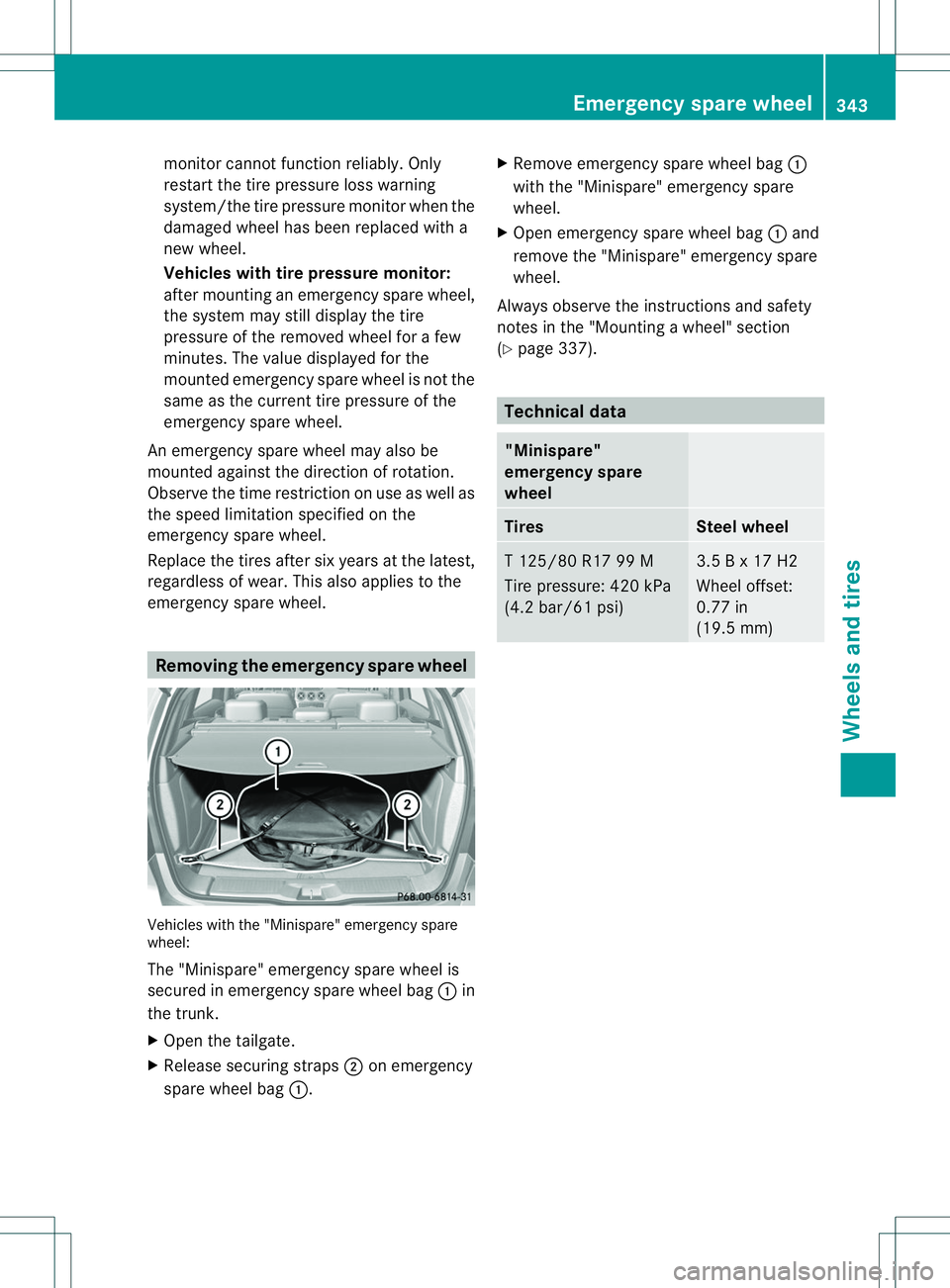
The "Minispare" emergenc yspare wheel is
secured in emergenc yspare wheel bag 001Ain
the trunk.
X Open the tailgate.
X Release securing straps 0010on emergency
spare wheel bag 001A. X
Remove emergenc yspare wheel bag 001A
with the "Minispare" emergenc yspare
wheel.
X Open emergenc yspare wheel bag 001Aand
remove the "Minispare" emergenc yspare
wheel.
Always observe the instructions and safety
notes in the "Mounting awheel" section
(Y page 337). Technical data
"Minispare"
emergency spare
wheel
Tires Steel wheel
T1
25/80 R17 99 M
Tire pressure: 420 kPa
(4.2 bar/61 psi) 3.5
Bx17H2
Wheel offset:
0.77 in
(19.5 mm) Emergency sparew
heel
343Wheels and tires Z