2014 MERCEDES-BENZ B-CLASS SPORTS load capacity
[x] Cancel search: load capacityPage 20 of 360
Labeling (overview)
........................329
Load bearing index (definition) ......335
Load index ..................................... 332
Load index (definition) ...................334
M+S tires ....................................... 314
Maximum loaded vehicle weight
(definition) ..................................... 334
Maximum loa donatire (definition) 334
Maximum permissible tire
pressure (definition) ....................... 334
Maximum tire loa d......................... 327
Maximum tire loa d(definition) .......334
MOExtended tires ..........................314
Optional equipment weight
(definition) ..................................... 335
PSI (pounds per square inch)
(definition) ..................................... 334
Replacing ....................................... 336
Service life ..................................... 314
Sidewall (definition) .......................335
Speed rating (definition) ................334
Storing ........................................... 336
Structure and characteristics
(definition) ..................................... 333
Summer tires ......................... 160, 314
Temperature .................................. 329
TIN (Tire Identification Number)
(definition) ..................................... 335
Tire bea d(definition) ...................... 335
Tire pressure (definition) ................335
Tire pressure s(recommended )...... 333
Tire size (data) ............................... 340
Tire size designation, load-bearing
capacity, spee drating .................... 330
Tire tread ....................................... 313
Tire tread (definition) .....................335
Total loa dlimit (definition) .............335
Traction ......................................... 328
Traction (definition) .......................335
Trea dwear ..................................... 328
Uniform Tire Quality Grading
Standard s...................................... 328
Uniform Tire Quality Grading
Standard s(definition) .................... 333
Unladen weight (definition) ............334
Wea rindicato r(definition) .............335
Whee lrim (definition ).................... 333
see Flat tire Top Tether
............................................ 60
Towing Important safety guidelines ...........305
Installing the towing eye. ...............306
Removing the towing eye. ..............306
Towing away
With both axle sonthe ground .......307
With front axle raised ..................... 307
Tow-starting
Emergency engine starting ............308
Important safety notes ..................305
Installing the towing eye. ...............306
Removing the towing eye. ..............306
Transmission
see Automatic transmission
Transmission position display .........144
Transporting the vehicle ..................307
Trim pieces (cleaning instructions) .290
Trip computer (on-board computer) 194
Trip odometer Calling up ....................................... 193
Resetting (on-board computer) ......195
Trunk
see Tailgate
Turn signals
Changing bulbs (front) ...................114
Changing bulbs (rear) ....................115
Display message ............................ 220
Switching on/off ........................... 106
Type identification plate
see Vehicle identification plate U
Unlocking Emergency unlocking .......................81
From insid ethe vehicle (central
unlocking button) ............................. 80 V
Vanity mirror (in the sun visor) ........263
Vehicle Correct use ...................................... 25
Data acquisition ............................... 26
Equipment ....................................... 22
Individua lsettings .......................... 202
Limited Warranty ............................. 2618
Index
Page 252 of 360
Useful information
i This Operator's Manual describes all
models and all standard and optional
equipment of your vehicle available at the
time of publication of the Operator's
Manual. Country-specific differences are
possible. Please not ethat your vehicle may
not be equipped with all features
described. This also applies to safety-
related system sand functions.
i Read the information on qualified
specialist workshops: (Y page 25).Loading guidelines
G
WARNING
If objects, luggage or loads are not secured or
not secured sufficiently, they could slip, tip
over or be flung around and thereby hit vehicle
occupants .There is arisk of injury,
particularly in the even tofsudden braking or
as udde nchange in direction.
Always store objectssot hat they cannot be
flung around. Secure objects, luggageor
loads against slipping or tipping before the
journey. G
WARNING
Combustion engines emit poisonous exhaust
gases such as carbon monoxide. If the tailgate
is open when the engine is running,
particularly if the vehicle is moving, exhaust
fumes could enter the passenger
compartment. There is arisk of poisoning.
Turn off the engine before opening the
tailgate. Never drive with the tailgate open.
The handling characteristics of aladen
vehicle are dependent on the distribution of
the load within the vehicle. For this reason,
you should observe the following notes when
transporting aload:
R Never exceed the maximum permissible
gross vehicle weight or the gross axle weight rating of the vehicle (including
occupants). The values are specified on the
vehicle identification plate on the B-pillar of
the driver's door.
R The cargo compartmentist he preferred
place to carry objects.
R Position heavy loads as far forwards as
possible and as low down in the cargo
compartmentasp ossible.
R The load must not protrude above the
upper edge of the seat backrests.
R Alwaysp lace the load against the rear or
front seat backrests. Make sure that the
seat backrests are securely locked into
place.
R Alwaysp lace the load behind unoccupied
seats if possible.
R Use the cargo tie down rings and the parcel
nets to transport loads and luggage.
R Use cargo tie-down rings and fastening
materials appropriate for the weight and
size of the load.
R Hook in the cargo net when loading.
R The maximum load capacity of the stowage
well under the cargo compartment floor is
55 lbs (25 kg).
R Secure the load with sufficiently strong and
wear-resistant tie-downs. pad sharp edges
for protection.
! Do not position the load on one part of the
folding cargo compartment floor only. The
maximum load capacity of the folding cargo
compartment floor is 220 lbs (100 kg).
Distribute the weight evenly to avoid
damaging the cargo compartment floor.
Place asolid board under the load if
necessary. Please note that the load on the
cargo compartment floor will be increased
when the load is lashed down. 250
Loading guidelinesStowage and features
Page 256 of 360
X
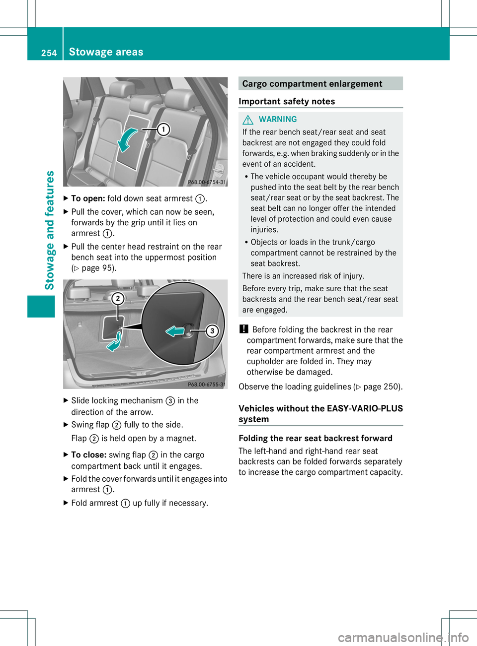
To open: foldd owns eata rmrest 001A.
X Pullt he cover, which can now be seen,
forwards by the grip until it lieson
armrest 001A.
X Pullt he center headr estraint on the rear
bench seat into the uppermost position
(Y page9 5). X
Slide locking mechanism 0023in the
direction of the arrow.
X Swing flap 0010fullytot he side.
Flap 0010is held open by amagnet.
X To close: swing flap 0010in the cargo
compartment back until it engages.
X Fold the cover forwards until it engages into
armrest 001A.
X Fold armrest 001Aup full yifnecessary. Cargo compartment enlargement
Important safety notes G
WARNING
If the rear bench seat/rea rseat and seat
backrest are not engaged they coul dfold
forwards, e.g. when braking suddenly or in the
event of an accident.
R The vehicl eoccupant would thereby be
pushed into the seat belt by the rear bench
seat/rea rseat or by the seat backrest. The
seat belt can no longer offer the intended
level of protection and could even cause
injuries.
R Objects or loads in the trunk/cargo
compartment cannot be restrained by the
seat backrest.
There is an increased risk of injury.
Befor eevery trip, make sure that the seat
backrests and the rear bench seat/rear seat
are engaged.
! Befor efolding the backrest in the rear
compartment forwards, make sure that the
rear compartment armrest and the
cupholder are folded in. They may
otherwise be damaged.
Observe the loading guidelines (Y page 250).
Vehicles without the EASY-VARIO-PLUS
system Folding the rear seat backrest forward
The left-hand and right-hand rear seat
backrests can be folded forwards separately
to increase the cargo compartment capacity.254
Stowage areasStowage and features
Page 258 of 360
Folding th
erears eat backres tback X
Mov ethe driver' sorfront-pa ssenger seat
forward if necessary.
! Mak esure that th eseat belt does not
become trapped when foldin gthe rear seat
backres tback .Otherwise, it could be
damaged.
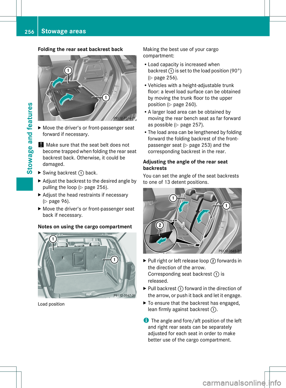
X Swing backrest 001Aback.
X Adjust the backrest to the desired angle by
pulling the loop (Y page 256).
X Adjust the head restraints if necessary
(Y page 96).
X Move the driver's or front-passenge rseat
back if necessary.
Notes on using the cargo compartment Load position Making the best use of your cargo
compartment:
R
Load capacity is increased when
backrest 001Ais set to the load position (90°)
(Y page 256).
R Vehicles with aheight-adjustable trunk
floor: alevel load surface can be obtained
by movin gthe trun kfloor to the upper
position (Y page 260).
R Al arge rload area can be obtained by
moving the rear bench seat as far forward
as possible (Y page 257).
R The load area can be lengthened by folding
forward the folding backrest of the front-
passenger seat (Y page 253) and the
corresponding backrest in the rear.
Adjusting the angle of the rear seat
backrests
You can set the angle of the seat backrests
to one of 13 detent positions. X
Pull right or left release loop 0010forwards in
the direction of the arrow.
Corresponding seat backrest 001Ais
released.
X Pull backrest 001Aforward in the direction of
the arrow, or push it back and let it engage.
X To ensure that the backrest has engaged,
lean firmly against backrest 001A.
i The angle and fore/aft position of the left
and right rear seats can be separately
adjusted for each seat in order to make
better use of the cargo compartment. 256
Stowage areasStowage and features
Page 261 of 360

Cargo net
Important safety notes G
WARNING
On its own ,the cargo ne tcanno tsecure or
restrain heav yobjects, items of luggag eand
heav yloads .You could be hit by an unsecured
load during sudden changes in direction,
braking or in the event of an accident .There
is an increased risk of injury or even fatal
injury.
Always store object ssothat they cannot be
flung around. Secure objects, luggage or
loads against slipping or tipping over, e.g. by
using tie downs, even if you are using the
cargo net.
It is important to use acargo net if you load
the vehicle with small object sabove the seat
backrests. For safety reasons, always use a
cargo net when transporting loads.
The cargo net is located in the stowage space
under the cargo compartment floor
(Y page 259).
X Open both Velcro fastener sand remove the
cargo net.
X Unroll and unfol dthe cargo net.
The joints on the uppe rand lowe rguide rod
should engage audibly.
The corresponding cargo ti edown rings for
tightening th ecargo ne tare in th ecargo
compartmen t(Ypage 257).
Attaching and tightening th ecargo net X
To attach and tighten: insert guide
rod 001Aintob racket 0010.
X Attac hbelt hook 0021to th ecargo tie-down
rin ga nd pull down on th eloose end of the
lashing strap until the cargo net is taut.
X After driving ashort distance, check the
tension of the cargo net and retighten it if
necessary.
X To loosen and detach: pull belt clamp
0023 up to reduce the tension in the lashing
strap.
X Unhook belt hook 0021from the cargo tie-
down ring.
X Detach guide rod 001Afrom bracket 0010.
X To stow: press the red button on the upper
and lower guide rod.
X Fold the cargo net and roll it up.
X Close the two Velcro fastener sonthe cargo
net holder. Stowage well under the cargo
compartment floor
Important safety notes G
WARNING
If you drive when the cargo compartment floor
is open, object scould be flung around, thus
striking vehicle occupants. There is arisk of
injury, particularly in the event of sudden
braking or asudden change in direction.
Always close the cargo compartment floor
before ajourney.
! The maximum load capacity of the
stowage well under the cargo compartment
floor is 55 lbs (25 kg).
Opening/closing the cargo
compartment floor Ab
racket for TIREFIT, the vehicl etool kit, etc.
is located underneath the cargo
compartment floor. Stowage areas
259Stowage and features Z
Page 297 of 360
X
Open the tailgate.
X Lift the cargo compartment floor up
(Y page 259).
i Towing eye 0010is located under tire
inflation compressor 001A.
Vehiclesw ithatire-change tool kit X
Open the tailgate.
X Lift the carg ocompartmen tfloor up
(Y page 259).
X Remove the tire-change too lkit.
The tire-chang etoolkit contains:
R Jack
R Lug wrench
R One pair of gloves
R Foldin gwheel chock Flat tire
Preparing th
evehicle
Your vehicle may be equipped with:
R MOExtende dtires (tires with run-flat
properties )(Y page 295)
Vehicle preparation is not necessary on
vehicles with MOExtende dtires.
R aT IREFIT kit (Y page 294)
Information on changing/mounting awheel
(Y page 337).
X Stop the vehicle on solid, non-slippery and
level ground, as far away as possible from
traffic.
X Switch on the hazar dwarnin glamps.
X Secure the vehicle against rollin gaway
(Y page 152).
X If possible ,brin gthe front wheels int othe
straight-ahead position.
X Switch off the engine.
X Remove the SmartKey fro mthe ignition
lock. X
All occupant smust get out of the vehicle.
Make sure that the yare not endangered as
the ydos o.
X Make sure that no one is near the danger
area while awheel is being changed.
Anyone who is not directly assisting in the
wheel change should, for example, stand
behin dthe barrier.
X Get out of the vehicle. Pay attention to
traffic conditions when doing so.
X Close the driver's door.
i Vehicles equipped with MOExtende dtires
are not equipped with aTIREFIT kit at the
factory. It is therefore recommende dthat
you additionally equip your vehicle with a
TIREFIT kit if you moun ttires that do not
feature run-flat properties ,e.g. winter tires.
AT IREFIT kit can be obtained fro ma
qualified specialist workshop. MOExtended tires (tires with run-flat
properties)
General notes With MOExtende
dtires (tires with run flat
characteristics), you can continue to drive
your vehicle even if there is atotal loss of
pressure in one or mor etires. The affected
tir em ust not show any clearly visible damage.
You can recognize MOExtende dtires by the
MOExtende dmarking which appears on the
sidewall of the tire. You will fin dthis marking
nex ttot he tire size designation, the load-
bearing capacity and the speed index
(Y page 330).
MOExtended tires may only be used in
conjunction with an active tire pressure loss
warning system.
If the pressur eloss warning message
appears in the multifunction display:
R Observe the instructions in the display
messages (Y page 231).
R Check the tire for damage.
R If driving on, observe the following notes. Flat tire
295Breakdown assistance
Page 327 of 360
X
Step 4: The resulting figure equalst he
available amount of cargo and luggagel oad
capacity. For example, if the "XXX" amount
equals1 400 lbs and there are five
occupants in the vehicle each with aweight
of 150 lbs, the amount of available cargo
and luggagel oad capacity is 650 lbs (1400
000F 750 (5 x150) =650 lbs).
X Step 5: Determine the combined weight of
luggagea nd cargo being loaded on the
vehicle. That weight may not safely exceed
the available cargo and luggagel oad
capacity calculated in step 4.
X Step 6(if applicable): If your vehicle will
be towing atrailer, load from your trailer
will be transferred to your vehicle. Refer to
this Operator's Manual to determine how
this reduces the available cargo and
luggagel oad capacity of your vehicle
(Y page 327). Loading the vehicle
325Wheels and tires Z
Page 331 of 360
not covered with ice or snow
.Take
appropriate car ewhend riving.
! Avoi dwheelspin .Thisc an lead to damage
to the drive train. Temperature
G
WARNING
The temperatur egrade for thi stire is
established for atire tha tisproperly inflated
and not overloaded.E xcessive speed,
underinflation, or excessive loading ,either
separatel yorincombination, can cause
excessive hea tbuild-up and possible tire
failure.
The temperatur egrades are A(the highest),
B, and C. Thes erepresent the tire's
resistanc etothe generatio nofheat and its
ability to dissipate heat when tested under
controlled conditions on aspecified indoor
laboratory test wheel. Sustained high
temperature can cause the material of the tire
to degenerat eand reduce tire life, and
excessive temperature can lead to sudden
tire failure. The grade Ccorresponds to alevel
of performanc ewhich all passenger car tires
must meet under the Federal Motor Vehicle
Safety Standard No. 109. Grades Band A
represent higher levels of performanc eonthe
laboratory test wheel than the minimum
required by law. Tire labeling
Overview of tire labeling
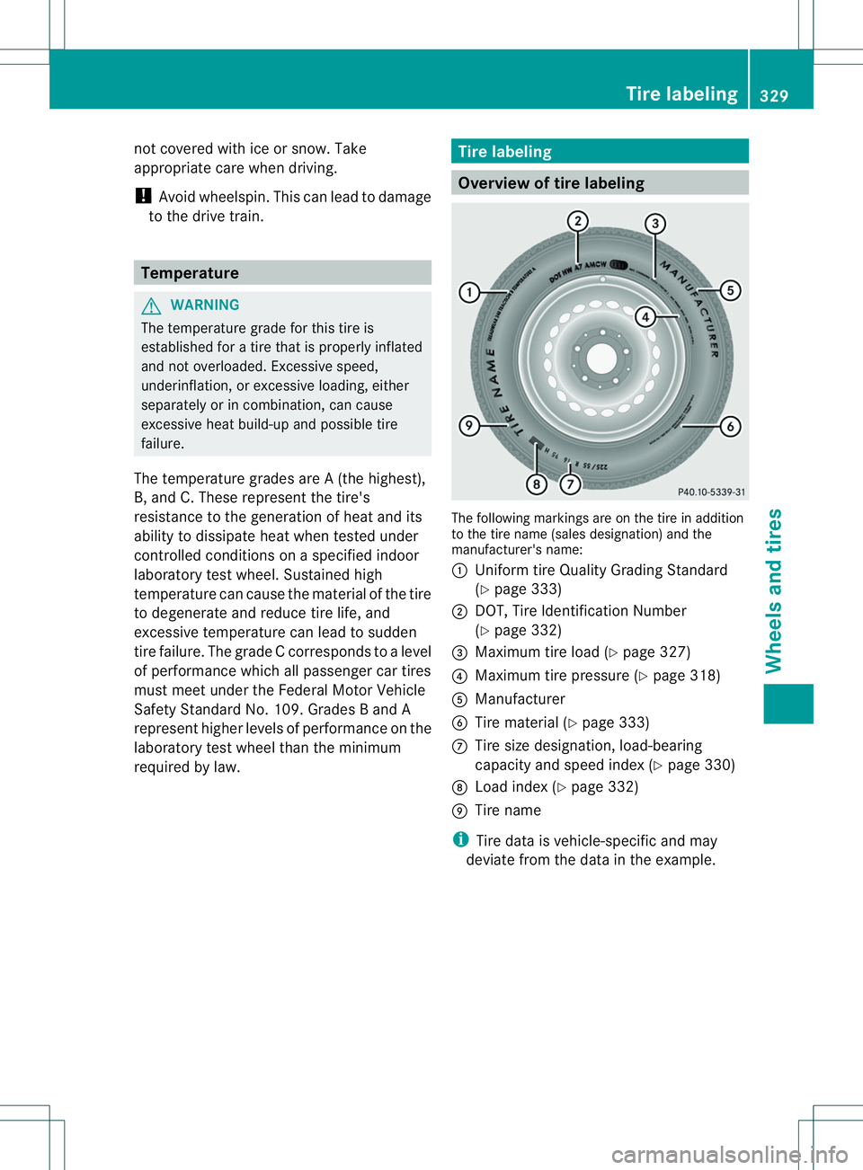
The following markings are on the tire in addition
to the tire name (sales designation) and the
manufacturer's name:
001A
Uniform tire Quality Grading Standard
(Ypage 333)
0010 DOT, Tire Identification Number
(Ypage 332)
0023 Maximum tire load (Y page 327)
0021 Maximum tire pressure (Y page 318)
001E Manufacturer
0024 Tire material (Y page 333)
0007 Tire size designation, load-bearing
capacity and speed index (Y page 330)
0008 Load index (Y page 332)
0009 Tire name
i Tire data is vehicle-specific and may
deviate from the data in the example. Tirel
abeling
329Wheels and tires Z