Page 73 of 367

The rear swing-doors are equipped with
a spring loaded system that locks
them at an approx. angle of 90 degrees
during opening.
Electrical closure from
inside
Close the two rear swing doors (first the
left, then the right) and press button D
fig. 115 located on the window control
panel.The opening angle of the two doors
may be increased for more convenient
loading and unloading. To carry out
this operation, press button A fig. 116;
the doors can then be opened by about
180 degrees.
38) 39)
WARNING
34) Once the dead lock system is
engaged it is impossible to open
the doors from inside the vehicle.
Therefore, before engaging the
system check that there is no one
left inside. If the remote control
battery is flat, the system can be
disengaged only by inserting
the key in either of the door locks
as described previously: in this
case the device remains active
only for the rear doors.
35) Before leaving the vehicle
parked with sliding doors open,
always check that the latch is
engaged.
36) Do not move the vehicle with
side doors open.
114
F1A0122
115
F1A0123
116
F1A0124
69
Page 74 of 367

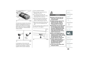
37) Before setting off after parking
or before moving the vehicle in
any way, ensure that the
footboard is fully stowed away. As
the movement of the platform is
linked to that of the sliding side
door, the
warning light in the
instrument panel comes on if it is
not fully retracted in the same
way as when the rear doors are
not shut.
38) This spring loaded system has
activation forces that were
designed for optimum comfort.
Accidental knocks or a strong
gust of wind may release the
springs and close the doors
spontaneously.
39) With the doors opened to 180
degrees, no locking system is
effective. Do not use this opening
with the vehicle parked on a
gradient or when it is windy.
ELECTRIC WINDOWSELECTRIC
Switches fig. 117 on the inner armrest
of the driver's door control the following
with the ignition key in the MAR-ON
position:
A: left front window opening/closing;
B: right front window opening/closing.
Continuous automatic
operation
All versions are equipped with
automatic raising and lowering of the
front, driver's side window.Keep one of the buttons pressed for
longer than half a second to operate
the automatic continuous window
operation function. The window stops
when it reaches the end of travel
position, or when the button is pressed
again.
IMPORTANT With the ignition key in the
STOP position or extracted, the
electric windows remain activated for
about 3 minutes and are deactivated
immediately when one of the doors
is opened.
Front passenger side
door
A dedicated switch for operating the
window is located on the inner armrest
of the passenger side front door.
40)
117
F1A0125
70
KNOW YOUR VEHICLE
Page 75 of 367

WARNING
40) Incorrect use of the electric
windows may be dangerous.
Before and during operation,
always check that nobody is
exposed to the risk of being
injured either directly by the
moving window or through
objects getting caught or by being
hit. When leaving the vehicle,
always remove the key from the
ignition switch to avoid the risk of
injury to anyone remaining in
the car due to accidental
operation of the electric windows.
BONNETOPENING
Proceed as follows:
❒open the driver's door to gain access
to the bonnet release handle;
❒pull the lever fig. 118 in the direction
indicated by the arrow;
❒lift lever A fig. 119 as shown in the
figure;
❒lift the bonnet and, at the same time,
release the bonnet stay fig. 120 from
its locking device D, then insert the
end C fig. 121 of the bonnet stay into
the housing E.
IMPORTANT Before opening the
bonnet, check that the windscreen
wiper arms are not lifted from the
windscreen.CLOSING
Proceed as follows:
❒hold the bonnet up with one hand
and with the other remove the stay
C fig. 121 from the housing E and fit
it back in its locking device D fig.
120;
❒lower the bonnet to approximately 20
centimetres from the engine
compartment and let it drop. Make
sure that the bonnet is completely
closed and not only fastened by the
locking device by trying to open it.
If it is not perfectly closed, do not try
to press the bonnet down but open
it and repeat the procedure.
IMPORTANT Always check that the
bonnet is closed correctly to prevent it
from opening while the vehicle is
travelling.118
F1A0126
119
F1A0339
71
Page 76 of 367
41) 42) 43)
WARNING
41) For safety reasons, the bonnet
must always be perfectly closed
while travelling. Make sure that
the bonnet is perfectly closed and
that the lock is engaged. If you
notice when driving that the
bonnet has not been properly
locked, stop immediately
and close the bonnet correctly.
42) Incorrect positioning of the stay
rod may cause the bonnet to drop
suddenly.
43) Perform these operations only
when the vehicle is stationary.
ROOF RACK/SKI
RACKTo fit the roof/ski rack, with provision for
versions H1 and H2, use the pins A
provided on the edges of the roof fig.
122.
Long wheelbase vehicles are equipped
with 8 pins; short or medium
wheelbase vehicles are equipped with 6
pins; vehicles with extra-long
wheelbases are equipped with 10 pins.
44) 45)5) 6)
IMPORTANT Follow the instructions
contained in the assembly kit carefully.
Assembly must be performed by
qualified personnel.
120
F1A0349
121
F1A0129
122
F1A0130
72
KNOW YOUR VEHICLE
Page 77 of 367

WARNING
44) After travelling for a few
kilometres, check to ensure that
the fixing screws for the
attachments are well tightened.
45) Evenly distribute the load and
take into account, when driving,
the increased responsiveness
of the vehicle to side wind.
IMPORTANT
5) The size of the loads you
transport must strictly comply
with currently applicable
regulations.
6) Never exceed the maximum
permitted loads (see “Technical
specifications” section).
HEADLIGHTSLIGHT BEAM ALIGNMENT
The correct alignment of the headlights
is essential for the comfort and safety
of the driver and other road users.
To ensure the best visibility when
travelling with the headlights on, the
headlight alignment must be correct.
Contact a Fiat Dealership to have
the headlights checked and adjusted.
HEADLIGHT ALIGNMENT
CORRECTOR
This device works with the ignition key
in the MAR-ON position and the dipped
beam headlights on.
The vehicle tilts backwards when it is
laden, raising the beam.
The beams must therefore be realigned
in this case.
Headlight alignment
adjustment
Press
or
on the control panel fig.
123.
The instrument panel display shows the
position in relation to the adjustment
set.IMPORTANT Check the alignment of
the light beams each time the weight of
the load transported changes.
FOG LIGHTS ALIGNMENT
(for versions/markets, where provided)
Contact a Fiat Dealership to have the
headlights checked and adjusted.
MODEMODE
123
F1A0326
73
Page 78 of 367

ADJUSTING THE
HEADLIGHTS WHEN
ABROAD
The dipped beam headlights are
aligned for operation in the country
where the vehicle was originally
purchased. When in countries where
you drive on the other side of the road,
you need to alter the beam direction
by affixing a specially designed
self-adhesive film in order not to dazzle
the vehicles travelling in the opposite
direction. Such film is provided by
Lineaccessori Fiat and is available at
Fiat Dealerships.
ABSThis is an integral part of the braking
system, which prevents one or more
wheels from locking or slipping
regardless of the road surface
conditions and braking intensity,
ensuring control of the vehicle even
during emergency braking.
The system intervenes when braking
and the wheels are about to lock,
typically in emergency braking or
low-grip conditions, when locking may
be more frequent.
The ABS ensures the direction of the
vehicle while braking and optimises the
braking distances at the same time.
The system also improves control and
stability of the car when braking on a
surface where the grip of the left and
right wheels varies, or when braking on
corners.
The system is completed by EBD
(Electronic Braking Force Distribution),
which distributes the braking action
between the front and rear wheels.
IMPORTANT To obtain the maximum
efficiency of the braking system, a
bedding-in period of about 500 km is
needed: during this period it is better to
avoid sharp, repeated and prolonged
braking.
46)
SYSTEM INTERVENTION
The driver can feel that the ABS has
come into action because the brake
pedal pulsates slightly and the system
gets noisier: it means that the car
speed should be altered to suit the type
of road surface.
47) 48) 48) 49) 50) 51) 52) 53)
MSR SYSTEM
(Motor Schleppmoment Regelung)
This system is an integral part of the
ABS and intervenes, if there is sudden
downshifting, restoring torque to the
engine, thereby preventing excessive
drive at the drive wheels which,
especially in poor grip conditions, could
lead to a loss in stability of the vehicle.
WARNING
46) The ABS exploits the grip
available to the full, but it cannot
improve it. Therefore, you should
take great care when driving on
slippery surfaces, without taking
unnecessary risks.
74
KNOW YOUR VEHICLE
Page 79 of 367

47) When the ABS intervenes and
you notice the brake pedal
pulsating, keep the pedal pushed
down and don’t be alarmed. This
will help you to stop in the
shortest distance possible,
depending on the road conditions.
48) If the ABS intervenes, it means
you have almost reached the grip
limit between the tyres and the
road surface: slow down to make
sure that you drive in accordance
with the available grip
49) The ABS can’t overrule the
natural laws of physics, and can’t
increase the grip available
according to the condition of the
road.
50) The ABS cannot prevent
accidents, including those due to
excessive speed on corners,
driving on low-grip surfaces or
aquaplaning.
51) The capability of the ABS must
never be tested irresponsibly and
dangerously, in such a way as
to compromise personal safety
and the safety of others.
52) For the correct operation of the
ABS, it is essential that the tyres
are of the same make and type on
all wheels, in perfect condition
and, above all, of the specified
type and dimensions.53) If the space-saver wheel (for
versions/markets, where
provided) is used, the ABS keeps
operating. Always remember
that the space-saver wheel, being
smaller than the original wheel,
provides less grip.
ESC (Electronic
Stability Control)
SYSTEM(for versions/markets, where provided)
The ESC system improves the
directional control and stability of the
vehicle in various driving conditions.
The ESC system corrects the vehicle’s
understeer and oversteer, distributing
the brake force on the appropriate
wheels. The torque supplied by the
engine can also be reduced in order to
maintain control of the vehicle.
The ESC system uses the sensors in
the vehicle to determine the trajectory
required by the driver through steering
and compares it with the real trajectory
of the vehicle. When the real trajectory
deviates from the desired trajectory, the
ESC system intervenes to counter the
car’s understeer or oversteer.
❒Oversteer: occurs when the vehicle is
turning more than it should according
to the angle of the steering wheel.
❒Understeer: occurs when the vehicle
is turning less than it should
according to the angle of the steering
wheel
The ESC system also includes the
following subsystems:
❒Hill Holder
75
Page 80 of 367

❒ASR
❒HBA
❒DST
❒ERM
54) 55) 56)
SYSTEM INTERVENTION
This is signalled by the flashing of
warning light
in the instrument panel,
to inform the driver that the vehicle is
in critical stability and grip conditions.
SYSTEM ACTIVATION
The ESC system switches on
automatically when the engine is
started and cannot be switched off.
HILL HOLDER SYSTEM
This system is an integral part of the
ESC system and facilitates starting on
slopes.
It is automatically activated in the
following conditions:
❒uphill: vehicle stationary on a road
with a gradient higher than 5%,
engine running, brake pressed and
gearbox in neutral or gear (other than
reverse) engaged;❒downhill: vehicle stationary on a road
with a gradient higher than 5%,
engine running, brake pressed and
reverse gear engaged.
When setting off, the ESC system
control unit maintains the braking
pressure on the wheels until the torque
necessary for starting is reached, or
in any case for a maximum of 2
seconds, allowing your right foot to be
moved easily from the brake pedal to
the accelerator.
When two seconds have elapsed,
without starting, the system is
automatically deactivated, gradually
releasing the braking pressure. During
this release stage, the typical brake
disengagement noise indicating that the
vehicle is going to move imminently
will be heard.
IMPORTANT The Hill Holder system is
not a parking brake; therefore, never
leave the vehicle without having
engaged the handbrake, turned the
engine off and engaged first gear,
so that it is parked in safe conditions
(for further information read the
"Parking" paragraph in the "Starting
and driving" chapter).ASR (AntiSlip
Regulation) SYSTEM
It is an integral part of the ESC system.
It automatically operates in the event
of one or both drive wheels slipping,
loss of grip on wet roads (aquaplaning)
and acceleration on slippery, snowy
or icy roads, etc.
Depending on the slipping conditions,
two different control systems are
activated:
❒if the slipping involves both drive
wheels, the ASR intervenes reducing
the power transmitted by the engine;
❒if the slipping only involves one of the
drive wheels, it intervenes
automatically braking the wheel that
is slipping.
58)
Engagement/ disengagement of the
ASR system
The ASR system switches on
automatically each time the engine is
started.
Whilst driving, the ASR can be switched
off and subsequently switched on
again by pressing the ASR OFF button
fig. 124.
57)
76
KNOW YOUR VEHICLE