Page 185 of 367
Existing nut
Existing hole
M12
M10 (3x)
172
F1A0164
181
Page 186 of 367
Existing hole
173
F1A0165
182
STARTING AND DRIVING
Page 187 of 367

INSTRUCTIONS FOR
USING THE REMOVABLE
BALL HEAD TOW BAR
36) 37) 38) 39) 40) 41)
Before setting off, check the correct
locking of the removable ball head tow
bar, as follows:
❒The green mark of the flywheel must
coincide with the green mark on the
tow bar.
❒The flywheel is in the stop position on
the tow bar (without slot).
❒Locked lock and key removed. The
flywheel cannot be removed.
❒Ball head bar firmly secured to the
housing pipe. Check by shaking
with a hand.
The fitting procedure must be repeated
if any of the 4 checked requirements
is not met.
If even only one of the requirements is
not met the tow hook must not be
used, as in this case there is risk of
accidents. Contact the joint
manufacturer.The ball head tow bar can be fitted and
removed manually, without needing
any tool.
Never use working tools or means, as
the mechanism could be damaged.
Never unlock in the case of trailer
attached to the vehicle or fitted rack.
When driving without trailer or rack the
ball head tow bar must be removed
and the closing plug must always
be inserted in the housing pipe. This
applies particularly if the visibility of the
number plate characters or of the
lighting system is reduced.Removable ball head
tow barfig. 174 - fig. 175 - fig. 176
1. Housing pipe - 2. Ball head tow bar
- 3. Locking balls - 4. Release lever -
5. Flywheel - 6. Cap - 7. Key - 8. Red
mark (flywheel) - 9. Green mark
(flywheel) - 10. Green mark (tow bar) -
11. Symbol (control release) - 12.
Closing plug - 13. Coupling pin - 14.
No slot between 2 and 5 - 15. Slot
of approx. 5 mm
174
F1A0380
175 - Locked position, driving
F1A0381
183
Page 188 of 367

Installing the ball head
tow bar
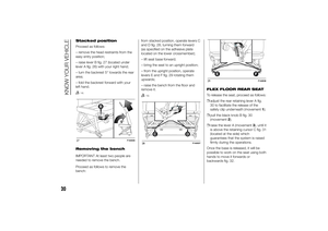
1. Remove the plug from the mounting
pipe.
The ball head tow bar is usually in the
released position when taken out from
the luggage compartment. This can
be observed by the flywheel spaced
from the tow bar, corresponding to
a slot of approx. 5 mm (see figure) and
by the red mark on the flywheel
directed to the green mark on the tow
bar.Please note that the tow bar can be
installed only when in these conditions.
If the locking mechanism of the tow
bar is disengaged before the
installation, or at any other time, and is
in the locked position, it must be
pre-loaded. The locked position can be
identified by the green mark of the
flywheel coinciding with the green mark
of the tow bar and by the flywheel in
the stop position on the tow bar,
namely without slot (see figure).
The locking mechanism is pre-loaded
as follows: with the key inserted and
the lock open, extract the flywheel
following the direction of the arrow and,
to pre-load, rotate according to the
direction of the arrow b until the stop.
The release lever is engaged and the
locking mechanism remains in the
pre-loading position even when the
flywheel is released. The tow bar must
be inserted in the housing pipe with the
coupling pin for the installation. Insert
from the bottom and push upwards.
The mechanism then locks
automatically. Keep your hands far from
the flywheel, as it rotates during the
locking procedure.2. The tow bar must be inserted in the
housing pipe with the coupling pin
for the installation. Insert from the
bottom and push upwards. The
mechanism then locks automatically.
Keep your hands far from the flywheel,
as it rotates during the locking
procedure.
3. Close the lock and always remove
the key. The key cannot be removed
when the lock is released. Apply the
protection cap on the lock.
Removing the tow bar
1. Remove the protection cap from the
lock and press it on the key grip. Open
the lock with the key.
2. Hold the tow bar firmly, remove the
flywheel following the direction of the
arrow and rotate according to the
direction of the arrow b until stopping,
so as to remove till the extracted
position. Then remove the tow bar from
the housing pipe. The flywheel can
then be released; it autonomously
stops in the released position.
3. Arrange the tow bar in the luggage
compartment so that it cannot be
dirtied or damaged by other
transported objects.
4. Insert the suitable plug in the
mounting pipe.176 - Released position, removed
F1A0382
184
STARTING AND DRIVING
Page 189 of 367
IMPORTANT
36) The removable ball head bar can
be repaired and disassembled by
the manufacturer only.
37) The supplied plate must be
applied in a visible point on the
vehicle, close to the mounting
pipe or inside the luggage
compartment.
38) Regularly remove all dirt
deposits from the ball head bar
and from the mounting pipe to
ensure a correct system
operation. The mechanical
components must be serviced at
the specified intervals. The lock
must be treated with graphite
only.
39) Periodically lubricate the joints,
the sliding surfaces and the balls
with grease without resin or oil.
Lubrication is also a further
corrosion protection.
40) When the vehicle is cleaned with
high-pressure jets, previously
remove the ball head bar and
insert the suitable plug. The ball
head plug must never be treated
with high-pressure jets.41) Two keys are supplied together
with the removable ball tow bar.
Note down the key number on the
pawl for any following order and
keep it.
185
Page 190 of 367

SNOW TYRESA Fiat Dealership will be happy to
provide advice concerning the most
suitable type of tyre for the customer's
requirements.
The performance of these tyres is
considerably reduced when the tread
depth is less than 4 mm. Replace them
in this case.
Due to the specific characteristics of
snow tyres, in normal weather
conditions or on long motorway
journeys, the performance of these
tyres is lower than that of standard
tyres. Their usage should therefore be
restricted in accordance with their
type approval.IMPORTANT When using snow tyres
with a maximum speed index below the
one that can be reached by the vehicle
(increased by 5%), place a notice in
the passenger compartment, plainly in
view, which states the maximum speed
allowed by the snow tyres (as per EC
Directive).
All four tyres should be the same (brand
and track) to ensure greater safety
when driving and braking as well as a
good manoeuvrability.
Remember that you should not change
the rotation direction of the tyres.
135)
WARNING
135) The maximum speed for snow
tyres marked "Q" is 160 km/h,
while it is 190 km/h for "T" tyres
and 210 km/h for "H" tyres. You
should, however, always comply
with the speed limits of the
highway code.
186
STARTING AND DRIVING
Page 191 of 367

SNOW CHAINSThe use of snow chains should be in
compliance with local regulations of
each country.
Snow chains can be fitted to the tyres
of the front wheels (drive wheels) only.
Use of Lineaccessori Fiat snow chains
is recommended. Check the tension
of the snow chains after the first few
metres have been driven.
42)
IMPORTANT With snow chains, use the
accelerator with extreme care to
prevent, or to limit as much as possible,
slipping of the drive wheels that could
cause chain breakage, resulting in
damage to the car body or mechanical
components.
IMPORTANT For versions fitted with
225/75 R16 tyre, use snow chains with
max. thickness 16 mm.
When travelling on snowy roads with
snow chains, it may be helpful to turn
the ASR off: in fact, in these conditions,
the driving wheels skidding when
moving off gives you better traction.
IMPORTANT
42) Keep your speed down when
snow chains are fitted; do not
exceed 50 km/h. Avoid potholes,
steps and pavements and avoid
driving for long distances on
roads not covered with snow to
prevent damaging the vehicle and
the roadbed.
PROLONGED
VEHICLE INACTIVITYIf the vehicle needs to be off the road
for longer than one month, the following
precautions must be taken:
❒park the vehicle indoors in a dry and,
if possible, well-ventilated place;
❒engage a gear;
❒check that the handbrake is not
engaged;
❒disconnect the negative battery
terminal; if the vehicle is equipped
with a battery disconnection function
(disconnector), see the description
of the procedure in the "Controls"
paragraph in the "Dashboard and
controls" section;
❒clean and protect the painted parts
using protective wax;
❒clean and protect the shiny metal
parts using special compounds
available commercially;
❒sprinkle talcum powder on the
windscreen and rear window wiper
rubber blades and lift them off the
glass;
❒slightly open the windows;
187
Page 192 of 367
❒cover the vehicle with a piece of
fabric or perforated plastic sheet. Do
not use compact plastic tarpaulins,
which prevent humidity from
evaporating from the surface of the
vehicle;
❒inflate tyres to +0.5 bar above the
standard specified pressure and
check it at intervals;
❒do not drain the engine cooling
system.
IMPORTANT If the vehicle is equipped
with an alarm system, switch off the
vehicle alarm with the remote control.
IMPORTANT After turning the ignition
key to STOP and having closed the
driver side door, wait at least one
minute before disconnecting the
electrical supply from the battery. When
reconnecting the electrical supply to
the battery, make sure that the ignition
key is in the STOP position and the
driver side door is closed.
188
STARTING AND DRIVING