Page 55 of 476
WARNING!
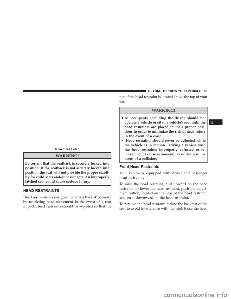
Be certain that the seatback is securely locked into
position. If the seatback is not securely locked into
position the seat will not provide the proper stabil-
ity for child seats and/or passengers. An improperly
latched seat could cause serious injury.
HEAD RESTRAINTS
Head restraints are designed to reduce the risk of injury
by restricting head movement in the event of a rear
impact. Head restraints should be adjusted so that thetop of the head restraint is located above the top of your
ear.
WARNING!
•
All occupants, including the driver, should not
operate a vehicle or sit in a vehicle’s seat until the
head restraints are placed in their proper posi-
tions in order to minimize the risk of neck injury
in the event of a crash.
• Head restraints should never be adjusted while
the vehicle is in motion. Driving a vehicle with
the head restraints improperly adjusted or re-
moved could cause serious injury or death in the
event of a collision.
Front Head Restraints
Your vehicle is equipped with driver and passenger
head restraints.
To raise the head restraint, pull upward on the head
restraint. To lower the head restraint, push the adjust-
ment button, located on the base of the head restraint,
and push downward on the head restraint.
To remove the head restraint recline the backrest of the
seat to avoid interference with the roof. Raise the head
Rear Seat Latch
4
GETTING TO KNOW YOUR VEHICLE 53
Page 56 of 476
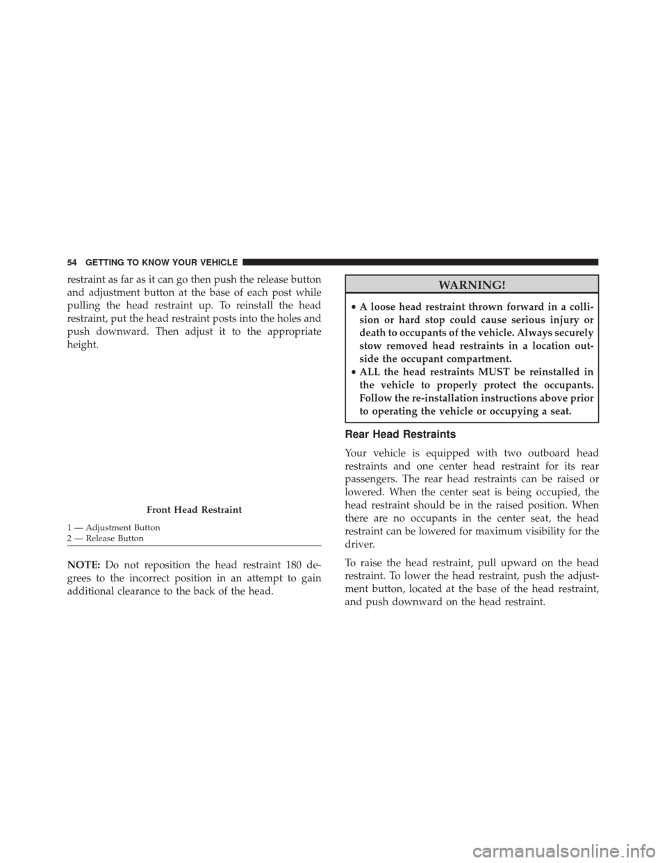
restraint as far as it can go then push the release button
and adjustment button at the base of each post while
pulling the head restraint up. To reinstall the head
restraint, put the head restraint posts into the holes and
push downward. Then adjust it to the appropriate
height.
NOTE:Do not reposition the head restraint 180 de-
grees to the incorrect position in an attempt to gain
additional clearance to the back of the head.WARNING!
• A loose head restraint thrown forward in a colli-
sion or hard stop could cause serious injury or
death to occupants of the vehicle. Always securely
stow removed head restraints in a location out-
side the occupant compartment.
• ALL the head restraints MUST be reinstalled in
the vehicle to properly protect the occupants.
Follow the re-installation instructions above prior
to operating the vehicle or occupying a seat.
Rear Head Restraints
Your vehicle is equipped with two outboard head
restraints and one center head restraint for its rear
passengers. The rear head restraints can be raised or
lowered. When the center seat is being occupied, the
head restraint should be in the raised position. When
there are no occupants in the center seat, the head
restraint can be lowered for maximum visibility for the
driver.
To raise the head restraint, pull upward on the head
restraint. To lower the head restraint, push the adjust-
ment button, located at the base of the head restraint,
and push downward on the head restraint.
Front Head Restraint
1 — Adjustment Button
2 — Release Button 54 GETTING TO KNOW YOUR VEHICLE
Page 57 of 476
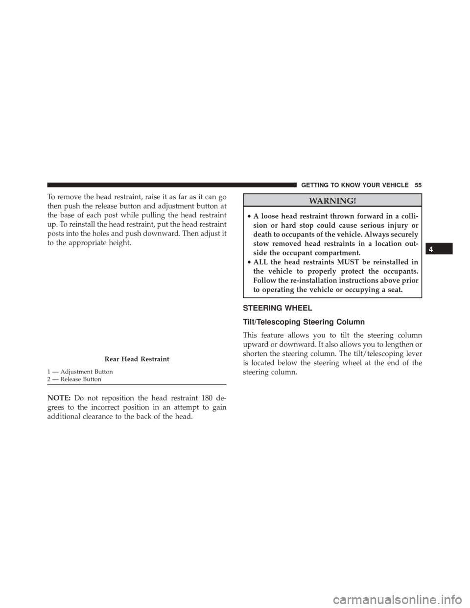
To remove the head restraint, raise it as far as it can go
then push the release button and adjustment button at
the base of each post while pulling the head restraint
up. To reinstall the head restraint, put the head restraint
posts into the holes and push downward. Then adjust it
to the appropriate height.
NOTE:Do not reposition the head restraint 180 de-
grees to the incorrect position in an attempt to gain
additional clearance to the back of the head.WARNING!
• A loose head restraint thrown forward in a colli-
sion or hard stop could cause serious injury or
death to occupants of the vehicle. Always securely
stow removed head restraints in a location out-
side the occupant compartment.
• ALL the head restraints MUST be reinstalled in
the vehicle to properly protect the occupants.
Follow the re-installation instructions above prior
to operating the vehicle or occupying a seat.
STEERING WHEEL
Tilt/Telescoping Steering Column
This feature allows you to tilt the steering column
upward or downward. It also allows you to lengthen or
shorten the steering column. The tilt/telescoping lever
is located below the steering wheel at the end of the
steering column.
Rear Head Restraint
1 — Adjustment Button
2 — Release Button
4
GETTING TO KNOW YOUR VEHICLE 55
Page 58 of 476
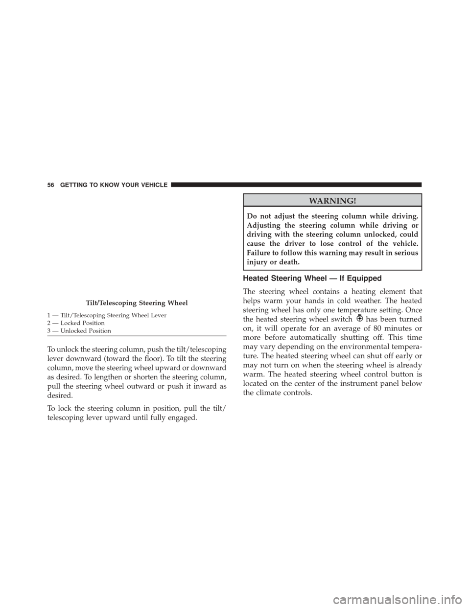
To unlock the steering column, push the tilt/telescoping
lever downward (toward the floor). To tilt the steering
column, move the steering wheel upward or downward
as desired. To lengthen or shorten the steering column,
pull the steering wheel outward or push it inward as
desired.
To lock the steering column in position, pull the tilt/
telescoping lever upward until fully engaged.
WARNING!
Do not adjust the steering column while driving.
Adjusting the steering column while driving or
driving with the steering column unlocked, could
cause the driver to lose control of the vehicle.
Failure to follow this warning may result in serious
injury or death.
Heated Steering Wheel — If Equipped
The steering wheel contains a heating element that
helps warm your hands in cold weather. The heated
steering wheel has only one temperature setting. Once
the heated steering wheel switch
has been turned
on, it will operate for an average of 80 minutes or
more before automatically shutting off. This time
may vary depending on the environmental tempera-
ture. The heated steering wheel can shut off early or
may not turn on when the steering wheel is already
warm. The heated steering wheel control button is
located on the center of the instrument panel below
the climate controls.
Tilt/Telescoping Steering Wheel
1 — Tilt/Telescoping Steering Wheel Lever
2 — Locked Position
3 — Unlocked Position 56 GETTING TO KNOW YOUR VEHICLE
Page 59 of 476
Auto On Comfort — If Equipped
If the external temperature is below 40 °F (5 °C) at each
start-up of the vehicle the heated steering wheel func-
tionality is turned on.
WARNING!
•Persons who are unable to feel pain to the skin
because of advanced age, chronic illness, diabe-
tes, spinal cord injury, medication, alcohol use,
exhaustion, or other physical conditions must
exercise care when using the steering wheel
heater. It may cause burns even at low tempera-
tures, especially if used for long periods.
• Do not place anything on the steering wheel that
insulates against heat, such as a blanket or steer-
ing wheel covers of any type and material. This
may cause the steering wheel heater to overheat.
MIRRORS
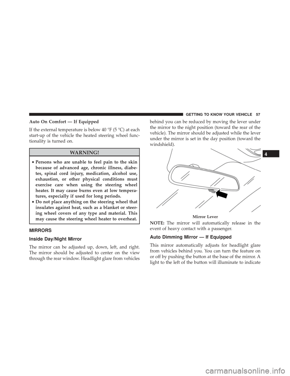
Inside Day/Night Mirror
The mirror can be adjusted up, down, left, and right.
The mirror should be adjusted to center on the view
through the rear window. Headlight glare from vehicles behind you can be reduced by moving the lever under
the mirror to the night position (toward the rear of the
vehicle). The mirror should be adjusted while the lever
under the mirror is set in the day position (toward the
windshield).
NOTE:
The mirror will automatically release in the
event of heavy contact with a passenger.
Auto Dimming Mirror — If Equipped
This mirror automatically adjusts for headlight glare
from vehicles behind you. You can turn the feature on
or off by pushing the button at the base of the mirror. A
light to the left of the button will illuminate to indicate
Mirror Lever
4
GETTING TO KNOW YOUR VEHICLE 57
Page 61 of 476
Folding Mirror
The exterior mirrors are hinged to allow the mirror to
pivot forward or rearward to help avoid damage. The
mirror has three detent positions: full forward, normal
and full rearward.
Heated Mirrors — If Equipped
These mirrors are heated to melt frost or ice. This
feature can be activated whenever you turn on
the Rear Window Defroster.
BLIND SPOT MONITORING (BSM) — IF
EQUIPPED
The Blind Spot Monitoring (BSM) system uses two
radar-based sensors, located inside the rear bumper
fascia, to detect highway licensable vehicles (automo-
biles, trucks, motorcycles, etc.) that enter the blind spot
zones from the rear/front/side of the vehicle.
When the vehicle is started, the BSM warning light will
momentarily illuminate in both outside rear view mir-
rors to let the driver know that the system is opera-
tional. The BSM system sensors operate when the
Folding Exterior Mirror
Rear Detection Zones
4
GETTING TO KNOW YOUR VEHICLE 59
Page 62 of 476

vehicle is in any forward gear or REVERSE and enters
stand-by mode when the vehicle is in PARK.
The BSM detection zone covers approximately one lane
width on both sides of the vehicle, 10 ft (3 m). The zone
length starts at the outside mirror and extends approxi-
mately 20 ft (6 m) beyond the rear bumper of the
vehicle. The BSM system monitors the detection zones
on both sides of the vehicle when the vehicle speed
reaches approximately 6 mph (10 km/h) or higher and
will alert the driver of vehicles in these areas.
NOTE:
•The BSM system does NOT alert the driver about
rapidly approaching vehicles that are outside the
detection zones.
• If a trailer is connected to the vehicle, it is necessary
to deactivate BSM system manually by settings menu
to avoid a miss-detection. Refer to “Uconnect Set-
tings” in “Multimedia” for further information.
The area on the rear fascia where the radar sensors are
located must remain free of snow, ice, and dirt/road
contamination so that the BSM system can function properly. Do not block the radar sensors located on the
rear fascia with foreign objects (bumper stickers, bicycle
racks, etc.).
The BSM system notifies the driver of objects in the
detection zones by illuminating the BSM warning light
located in the outside mirrors in addition to sounding
an audible (chime) alert and reducing the radio volume.
Refer to “Modes Of Operation” in this section for
further information.
Rear Sensor Locations
60 GETTING TO KNOW YOUR VEHICLE
Page 63 of 476
The BSM system monitors the detection zone from three
different entry points (side, rear, front) while driving to
see if an alert is necessary. The BSM system will issue an
alert during these types of zone entries.Entering From The Side
Vehicles that move into your adjacent lanes from either
side of the vehicle.
BSM Warning Light
Side Monitoring
4
GETTING TO KNOW YOUR VEHICLE 61