Page 217 of 244

25 Heater rear window Coupe/
heated rear window Roadster
26 Drivers side power window
27 Passengers s ide power window
28 Not use")
No. Equipment 24 Transmission (control unit)
25 Heater rear window Coupe/
heated rear window Roadster
26 Driver's side power window
27 Passenger's s ide power window
28 Not used
29 Washer pump
30 Cigarette lighter
31 Starter
32 Steering column module
33 Instrument cluster
34 Radio navigation system, radio
35 Audio amplifier
36 Engine (control un it)
37 CAN (Gateway)
38 Cigarette lighter
39 Not used
40 Not used
41 Not used
42 Not used
43 Not used
44 Not used
45 Not used
46 Not used
47 SOARS
tuner, cell phone pack-
age, TV tuner
48 VOA inte rface
49 Not used
Fuse location, left side of engine
compartment Amps
15
30/20
30
30
15
20
40
5
5
20/15
30 10
5
20
5
5
Fig. 164 Illustrat ion of fuse ho lder on left side of en
gine compart ment: fuses (without fuse cover)
Fuse s and bulb s 215
Some of the equipment items listed are op
tiona l or only avai lab le on certain model con
figurations.
Note th at the foll owing t abl e is ac cur ate at
the time of going t o pre ss and i s subject to
ch ang e.
Fus e holder (bla ck )
No. Equipment Amps
1 Not used
2 Not used
3 Not used
4 Not used
Anti-theft warning system (sen-
5 sor), anti-theft warning system
5
(horn)
6 H
eadlamp washer system
30
Electric f uel pumps (supp ly),
7 volume contro l valve/Interrelais 15/10
(5-cy l.)
8 W indshield w ipers 30
9 Heated
seats (driver and pas-
25
senger)
10 L
umbar support (driver and
10
passenger)
11 Not used
12 Vent
ilation blower
40
Fu se holder (brown )
No. Equipment Amps
1 Not used
2 Electric
fuel pump (5-cyl.)
30
3 Not used
4 Not used
Relay coil relay volume cont ro l
5 va
lve (4-cy l.)/02 sensors (5 -
5/10
cyl.)
6 02 sensors 10
7 Positioning valves pre-wired en-
10
g ine harness
8 Ignition coi ls 20
9 Eng
ine (control unit)
25
10 Water pump de layed-off 10
Page 218 of 244
 5
12
Activated charcoal fi lter/charge
10 pressure contro l valve
Bulbs
Replacing light bulbs
For your safety, we r")
216 Fuse s a nd bul bs
No. Equipment Amps
11 Feed (brake pedal) 5
12
Activated charcoal fi lter/charge
10 pressure contro l valve
Bulbs
Replacing light bulbs
For your safety, we recommend that you have
your authorized Audi dealer replace burned
out bulbs for you .
It is becoming increasingly more and more
difficult to replace vehicle light bulbs since in
many cases, other parts of the car must first
be removed before you are able to get to the
bulb . Th is appl ies especially to the l ight bulbs
in the front of your car which you can only
reach through the engine compartment.
Sheet metal and bulb holders can have sharp
edges that can cause ser ious cuts, and parts
must be co rrectly taken apart and then prop
e rly put back together to help prevent break
age of parts and long term damage from wa
ter that can enter housings that have not been properly resealed.
For your safety, we recommend that you have
your author ized Audi dealer replace any bulbs
for you, since your dealer has the proper tools,
the correct bu lbs and the expertise.
Gas disc harg e la mps (X enon l ig ht s}*:
Due to the high electrical voltage, have the
bulbs replaced by a qualified technician.
Headlights with Xenon light can be identified
by the high voltage sticker.
A WARNING
Contact with high-voltage components of
the electrical system and improper re
placement of gas discharge (Xenon) head
light bulbs can cause serious personal in
jury and death.
- Xenon bulbs are pressurized and can ex
plode when being changed. -
Changing Xenon lamps requires the spe
cial tra ining, instructions and equip
ment.
- Only an authorized Audi dealer or other
qualified workshop should change the
bulbs in gas discharge lamps.
A WARNING
=
There are parts with sharp edges on the
openings and on the bulb holders that can
cause ser ious cuts.
- If you are uncertain about what to do,
have the work performed by an author
ized Audi dealer or other qualified work
shop. Serious personal injury may result
from improperly performed work.
@ Tips
- If you must replace the light bulbs your
self, a lways remember that the eng ine
compartment of any vehicle is a hazard
ous area to work in. A lways read and
heed all WARNINGS
¢page 165, Work
ing in the engine compartment¢.&..
-It is best to ask your authorized Audi
dealer whenever yo u need to change a
bulb .
-
Page 219 of 244

Emergency situations
General
This chapter is intended for trained emer
gency crews and working personnel who
have the necessary tools and equipment to
perform these operations.
Starting by pushing or
towing
(D Note
Vehicles with an automatic transmission
cannot be started by pushing or towing .
Starting with jumper
cables
If necessary, the engine can be started by
connecting it to the battery of another vehi
cle.
If the engine should fail to start because of a
discharged or weak battery, the battery can be
connected to the battery of
another vehicle,
using a
pair of jumper cables to start the en
g ine.
Jumper cables
Use only jumper cables of sufficiently
largecross section to safely carry the starter
current. Refer to the manufacturer's specifica
tions.
Use only jumper cables which have
insulated
termina l clamps and are properly marked for
distinction :
plus(+) cable in most cases colored red
minus(-) cable
in most cases colored black.
_& WARNING
Batteries contain electricity, acid, and gas.
Any of these can cause very serious or fatal
injury. Follow the instructions below for
safe handling of your vehicle's battery.
- Always shield you r eyes and avoid lean
ing over the battery whenever possible.
Emergency situations 21 7
-A discharged battery can already freeze
at temperatures just below 32 °F (0 °C).
Before connect ing a jumper cable, the
frozen battery must be thawed com
pletely, otherwise it could explode .
- Do not allow battery acid to contact eyes
or skin . Flush any contacted area with
water immediately .
- Improper use of a booster battery to
start a vehicle may cause an explosion.
- Vehicle batter ies generate explosive gas
es. Keep sparks, flame and lighted c iga
rettes away from batteries.
- Do not try to jump start any veh icle w ith
a low ac id level in the battery.
- The voltage of the booster battery must
also have a 12-Volt rating. The capacity
(Ah) of the booster battery should not be
lower than that of the discharged bat
tery. Use of batteries of diff erent voltage
or substantially different "Ah" rat ing
may cause an exp losion and personal in
jury.
- Never charge a frozen battery. Gas trap
ped in the ice may cause an explosion.
- Never charge or use a battery that has
been frozen . The battery case may have
be weakened.
- Use of batter ies of different voltage or
substantially different capacity (Ah) rat
ing may cause an exp losion and injury .
The ca pa city (Ah) of the booster battery
should not be lower than that of the dis
charged battery.
- Before you check anything in the engine
compartment, always read and heed all
WARNINGS
c::;,page 165, Working in the
engine compartment.
(D Note
- App lying a higher voltage booster bat
tery will cause expensive damage to sen
sit ive electronic components, such as
control units, relays, rad io, etc .
- There must be no electrical contact be
tween the vehicles as otherwise current
could already start to flow as soon as the
posit ive(+) terminals are connected. ..,. •
•
Page 220 of 244

218 Emergency situations
@ Tips
The discharged battery must be properly
connected to the vehicle's electrical sys
tem.
Use of jumper cables
Make sure to connect the jumper coble
clomps in exactly the order described below!
Fig. 165 Engine compart ment: Co nnectors for jumper
cables and charger
Fig. 166 Jump starting with the battery of another ve
hicle: @discharged veh icle batte ry,® booste r battery
The procedure described below for connecting
jumper cables is intended to provide a jump
start for your veh icle.
Preparatory measures
1. Do not jump start a frozen battery! Re
place such a battery!
2 . Otherwise apply the hand brake and put
the selector lever into P position.
3. For both vehicles switch off all consumers
and the ign ition.
Connecting/disconnecting the jumper
cable .
4. Connect one end of the red jumper cable
on the
jump start bolt@q fig. 166
(Bolts under red cover = "positive") of the
vehicle to be started @.
5. Connect the other end of the red jumper
cable to the positive terminal @of the
booster battery @.
6. Connect one end of the black jumper ca
ble to the negat ive terminal @of the
booster battery @.
7. Connect the other end of the black jumper
cable to the negative terminal (bolt head)
@ in the external start ing point @ of
your vehicle.
8. Route the jumper cables so that they can
not catch in any rotating parts in the en
gine compartment.
Starting the engine
9. Start the engine of the vehicle providing
assistance and allow it to run at id le .
10. Now start the engine of the vehicle with
the discharged battery, wait for two to
three minutes until the engine "runs"
smoothly.
11. If the eng ine does not start: Stop try ing
after 10 seconds and then try again after
about 30 seconds.
12. In the vehicle that has received start as
sistance, turn on the heater blower and
the rear window heating to elim inate any
vo ltage peaks when disconnecting . Driv
ing lights must be switched off!
13 . Disconnect the cable while the engine is
running exactly in
reverse order to that
described in¢
page 218, Connecting/dis
connecting the jumper coble ..
When do
ing so, make sure that the cable cannot
contact rotating eng ine parts.
14. Close the cover on the positive terminal.
The battery is vented to the outside to prevent
gases from entering the vehicle inter ior. Make
sure that the jumper clamps are well connect
ed with their
metal parts in full contact with
the battery terminals.
A WARNING ~
To avoid serious personal injury and dam-
age to the vehicle, heed all warnings and
Page 221 of 244

instructions of the jumper cable
manufacturer. If in doubt, call for road
service.
- Jumper cables must be long enough so
that the vehicles do not touch.
- When connecting jumper cables, make
sure that they cannot get ca ught in any
moving parts in the eng ine compart
ment.
- Before you check anything in the engine
compartment, always read and heed all
WARNINGS
Q page 165, Working in the
engine compartment.
(D Note
Improper hook-up of jumper cables can ru
in the generator.
-Always connect POSITIVE(+) to POSI TIVE(+), and NEGATIVE( -) to NEGATIVE
( - ) ground post of the battery manager
control unit.
- Check that all screw plugs on the battery
cells are screwed in firmly . If not, tighten
plugs prior to connecting clamp on nega
tive battery terminal.
- Please note t hat the procedure for con
nect ing a jumper cable as described
above applies spec ifically to the case of
your vehicle be ing j ump started. When
you are giv ing a jump start to anothe r ve
hi cle, do
not connect the negat ive (-) ca
ble to the negative(- ) terminal on the
discharged battery ©- Instead, securely
connect the negative (-) cable to either a
solid metal component that is firmly bo lted to the engine block or to the en
gine block itself. If the battery that is be
i ng charged does not vent to the outside,
es caping ba tte ry gas cou ld ig nite and ex
plo de!
Em erg en cy si tuation s 219
Emergency towing
with commercial tow
truck
General hints
Your Audi requires special handling for tow
ing.
T he following information is to be used by
commercial tow truck operators who know
how to operate their equipment safely.
- Never tow your Audi , towing will cause
damage t o the engine a nd transmi ssion.
- Never wrap th e safet y chain s or winch ca
ble s ar ound the brak e lin es.
- To preven t unne cess ary dam age, your Aud i
mu st be transported with a car carrier
(flatbed truck ).
- To load th e vehi cle on to the fl at bed , use
the towing lo op found in the vehicle to o ls
and attach to the front o r rear anchorage
Q poge 220 and Qpoge 221.
A WARNING
A veh icle being towed is not safe for pas
sengers. Never allow anyone to ride in a
vehicle be ing towed, for any reason.
-
•
•
Page 222 of 244

Do not install the front towing loop until it is
needed.
Fig. 1 67 Fro nt bumper : rem ov ing t he grill
Fi g. 16 8 Fron t bum")
220 Emergency situations
Front towing loop (Version A)
Do not install the front towing loop until it is
needed.
Fig. 1 67 Fro nt bumper : rem ov ing t he grill
Fi g. 16 8 Fron t bumper: screw ing in the tow ing loop
The towing loop fi ts into the th readed hole lo
c at ed on the r igh t si de of the fron t bumper
behind the g rill .
... Remove the screwdrive r and tow ing loop
from the vehicle tool kit
~ page 205 .
... Inse rt the screw driver into the s lot as show n
and press toward the ce nte r of the vehicle
¢
fig. 167 . At the same time, pull the grill
forward and out .
.,. Screw the towing loop tight ly into the
t h readed hole as far as it will go¢
fig. 168.
When it is no longer needed, unscrew the
towline eye and put it back into the on -board
too lkit . Make sure to have the towline eye
stored in the vehicle at a ll times.
When insta lling the gri ll for the air duct, be
sure that the tabs on the gr ill are first insert
ed into the ir guides on the veh icle. Then push
the gr ill into position .
A WARNING
-
If the towing lo op is not screwed in as far
as it will go, the t hread can pull out when
the veh icle is towed - potent ia l risk of an
accident.
Front towing loop (Version B)
Do not install the front towing loop until it is
needed .
Fig. 169 Right fro nt sect io n : r em ov ing the air in take
g ri lle
Fi g. 170 Rig ht fro nt sect io n w it h plastic cove r
A threaded opening with left-hand threads is
located at the front right of the bumper be
hind the air intake grille. The towing loop is
insta lled i n this opening .
.,. Remove the screwdriver and the towing loop
from the vehicle tool kit¢
page 205 .
... Reach through the air intake grille, grip the
hor izontal fi ns and pull it forward to re
move.
... Use the screwdrive r to pry the plastic cov er
off ¢
fig. 170.
... In stall th e tow ing loop in the threade d
open ing and tighten it un til it stops
¢ page 220, fig . 168 . .,..
Page 223 of 244

Remove the towing loop when you are done
using it and place it back in the vehicle tool
kit. A lways keep the tow ing loop in the vehi
cle.
When insta lling the air intake grille, insert the
tabs on the grille in the mounts on the vehicle
first . Then press the gri lle in to secure it.
A WARNING
If the towing loop is not tightened until it
stops when installing, the threads may be
pulled out when tow ing the veh icle and
that could cause an accident.
Rear towing loop
Do not install the rear towing loop until it is
needed.
Fig. 171 Right rea r sect ion
Fi g. 17 2 Rear bumper: screwing in t he tow ing loop
On the r ight side under the rear bumper there
i s a t hreaded hole for the tow ing loop. The
threaded hole is pro tected by a cover.
"' Remove the towing loop from the vehicle
toolkit~
page 205 .
"'Press the right side of the cover i nward
f orcefully to remove it from the b umper.
¢fig. 171.
Emergenc y situ ation s 221
"'Screw the towing loop t ightly into the
threaded ho le as far as it wi ll go.
When it is no longe r needed, unscrew the
towing loop and put it back into the vehicle
toolkit . Be sure to have the towing loop sto red
in the vehicle at all times.
A WARNING
If t he tow ing loop is not screwed in as far
as it will go, the thread can pull out when
the vehicle is towed -potent ia l risk of an
accident.
loading the vehicle onto a flatbed truck
Fi g. 17 3 Vehicle on flatbed truck
Front hook up
"'Align the vehicle wi th the centerline of the
car carrier ramp.
"' Attach the winch hook to the front towline
eye prev iously insta lled.
Rear hook up
"' Alig n the vehicle wi th the center line of the
car car rier ramp .
"' Attach the winch hook to the rear tow line
eye previously insta lled.
(D Tips
Check caref ully to ma ke s ure the hook-up
i s secure before moving the car up the flat
bed truck ramp.
Page 224 of 244

222 Emergency situations
Lifting vehicle
Lifting with workshop hoist and with
floor jack
The vehicle may only be lif ted at the lifting
points illustra ted.
F ig. 174 Rear lift in g poin t (ri gh t side)
Fi g. 1 75 Fro nt lift in g po int (r ig ht s ide)
• Read and heed WARNI NG ¢,& .
• Locate lifting points
r=> fig . 174 r=> fig . 1 75 .
• Adjust lift ing arms of wor ks h op hoist or
floor jack to match vehicle lifting points.
• In se rt a rubber pad between the floor jack/
workshop hoist and the lifti ng po ints.
If you must lift your vehicle with a floor jack
to work underneath, be sure the vehicle is safely supported on stands intended for this
purpose.
Front lifting point
The lifting point is locate d on t he floor pan re
info rcement about at the same level as the
jac k mounting point
r=> fig. 175. Do not lift
the vehicle at the vertical sill reinforcement.
Rear lifting point
The lifting point is locate d on t he vertical rein
forceme nt of the lower s ill for t he on boa rd
j ac k
t:!>fig . 174.
Lifting with vehicle jack
Refer to r=>page 210.
/n.. WARNING
-To re duce the risk of ser ious injury and
ve hicl e damage .
- Always lift th e ve hicle o nly at t he spe
c ia l works hop hoist and floor jac k lift
p o ints illust rated
t:!> fig . 17 4 and
r=> fig. 175.
- Fa il u re to lift th e veh icle at th ese
p oi nts co ul d cau se the vehicle to tilt or
f a ll from a li ft if th ere is a ch an ge in ve
h icl e weig ht distr ib utio n an d ba lan ce.
T his mi ght happ en, for ex ample, when
h eavy com ponent s such as the engine
b lock o r tra nsmissi on are remove d.
- Wh en removin g heavy c ompone nts like
these , anch or vehicle to hoist or ad d co r
respon ding we ights to maintain t he cen
ter of gravity. Ot herwise , th e ve hicle
might tilt or slip off the ho ist, causing
serio us pe rsonal injury.
(D Note
-Be aware o f the followin g points bef ore
liftin g the vehicle:
- The vehicle should never be lifted or
jacked up from underneath the engine
oil pan, the transmission housing, the
front or rear axle or the body side members. This could lead to seriou s
damage.
- To avoid damage to the underbody or
chassis frame, a rubber pad must be inserted between the floor jack and
the lift points.
- Before driving over a workshop hoist,
check that the vehicle weight does not
exceed the permissible lifting capacity
of the hoist .
- Before driving over a workshop hoist,
ensure that there is sufficient clear
ance between the hoist and low parts
of the vehicle.
-
 1
1 2
2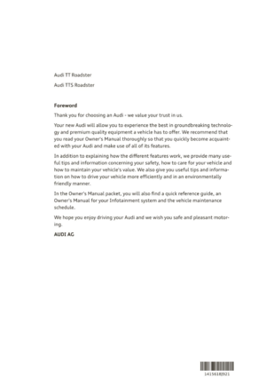 3
3 4
4 5
5 6
6 7
7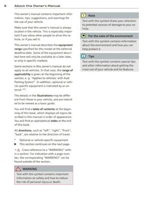 8
8 9
9 10
10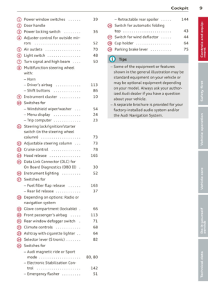 11
11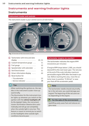 12
12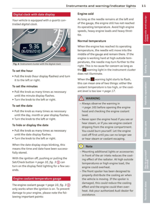 13
13 14
14 15
15 16
16 17
17 18
18 19
19 20
20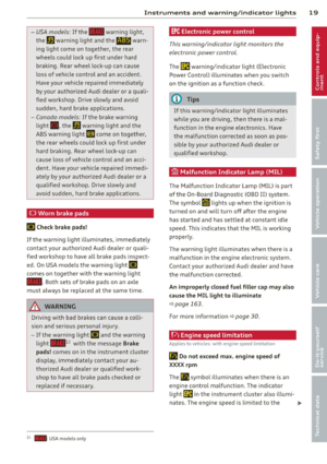 21
21 22
22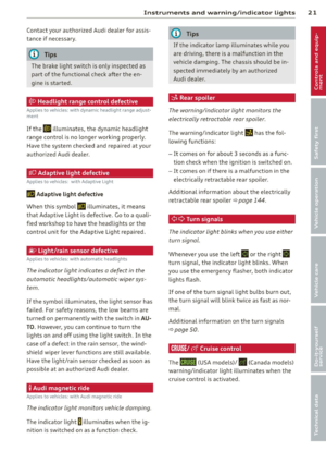 23
23 24
24 25
25 26
26 27
27 28
28 29
29 30
30 31
31 32
32 33
33 34
34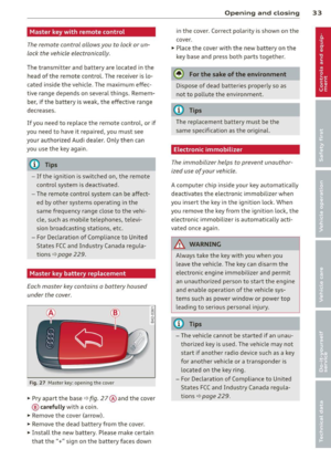 35
35 36
36 37
37 38
38 39
39 40
40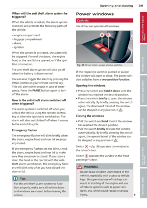 41
41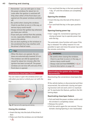 42
42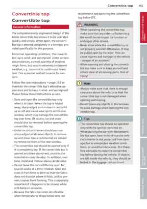 43
43 44
44 45
45 46
46 47
47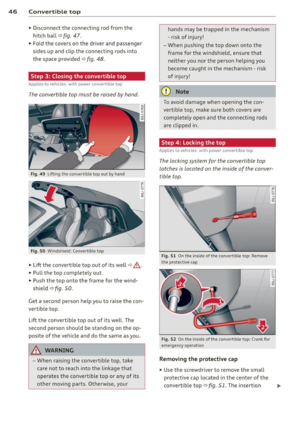 48
48 49
49 50
50 51
51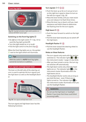 52
52 53
53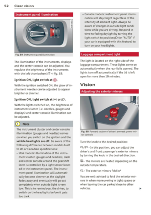 54
54 55
55 56
56 57
57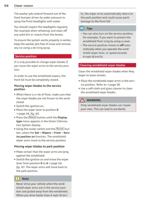 58
58 59
59 60
60 61
61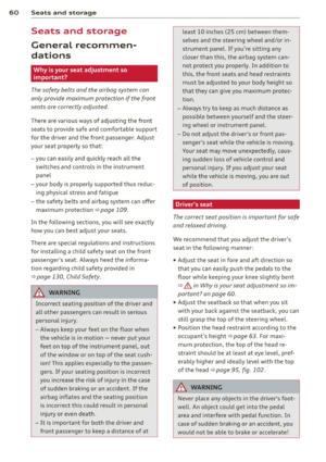 62
62 63
63 64
64 65
65 66
66 67
67 68
68 69
69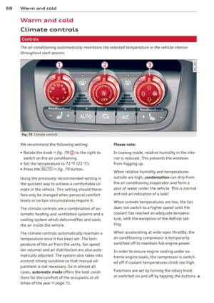 70
70 71
71 72
72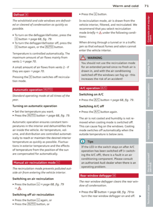 73
73 74
74 75
75 76
76 77
77 78
78 79
79 80
80 81
81 82
82 83
83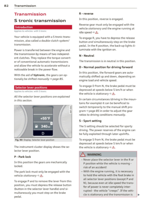 84
84 85
85 86
86 87
87 88
88 89
89 90
90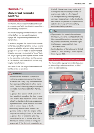 91
91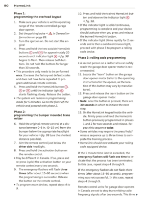 92
92 93
93 94
94 95
95 96
96 97
97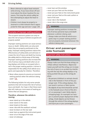 98
98 99
99 100
100 101
101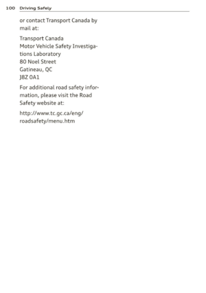 102
102 103
103 104
104 105
105 106
106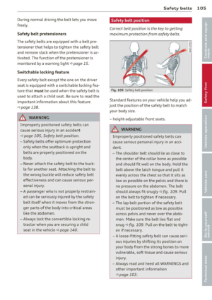 107
107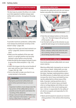 108
108 109
109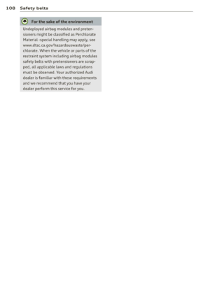 110
110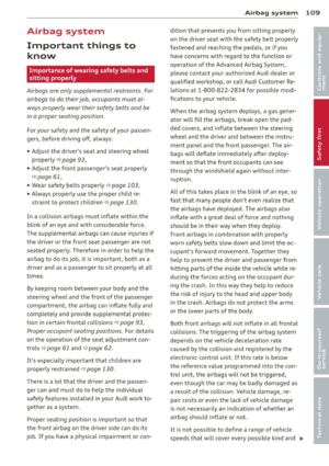 111
111 112
112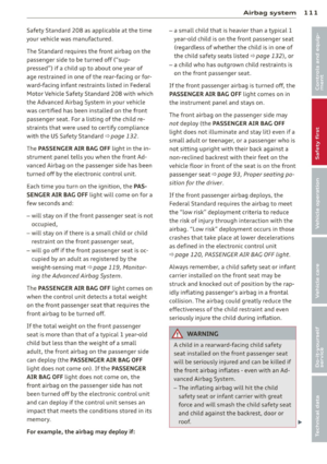 113
113 114
114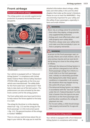 115
115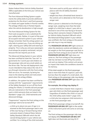 116
116 117
117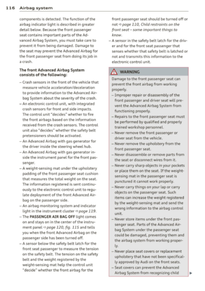 118
118 119
119 120
120 121
121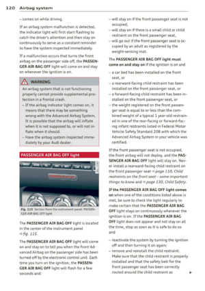 122
122 123
123 124
124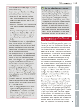 125
125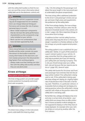 126
126 127
127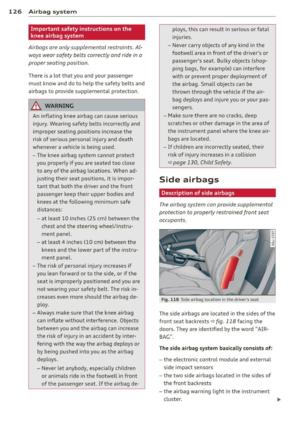 128
128 129
129 130
130 131
131 132
132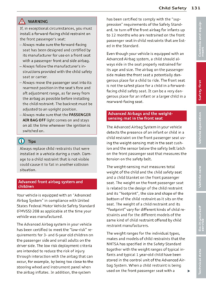 133
133 134
134 135
135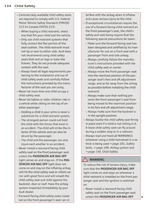 136
136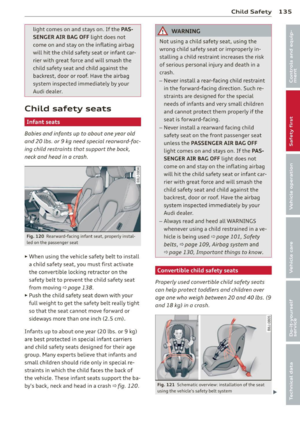 137
137 138
138 139
139 140
140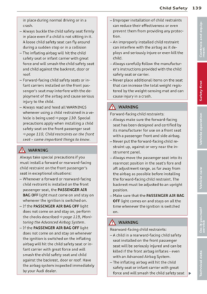 141
141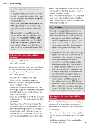 142
142 143
143 144
144 145
145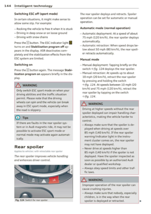 146
146 147
147 148
148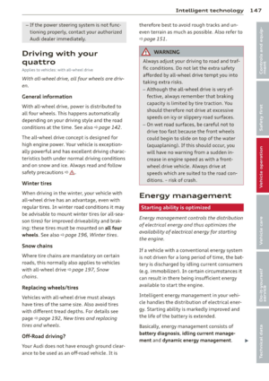 149
149 150
150 151
151 152
152 153
153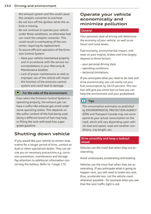 154
154 155
155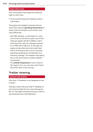 156
156 157
157 158
158 159
159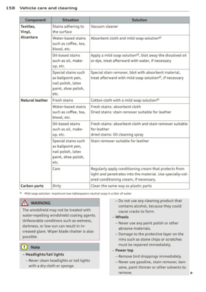 160
160 161
161 162
162 163
163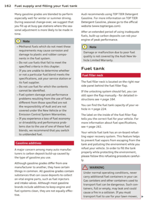 164
164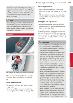 165
165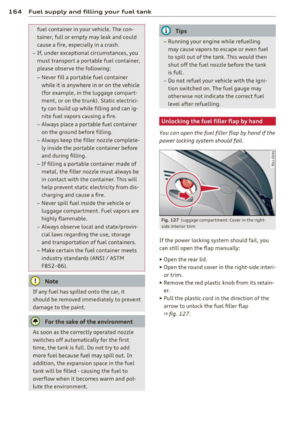 166
166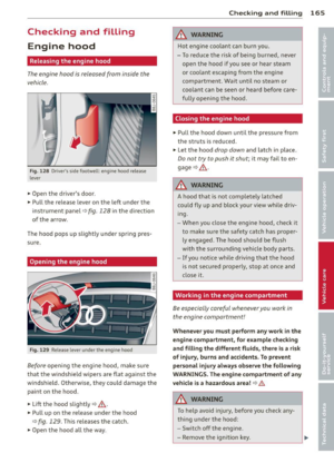 167
167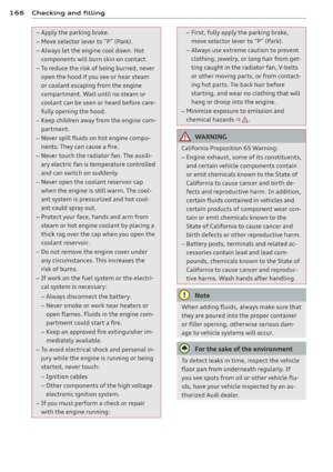 168
168 169
169 170
170 171
171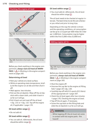 172
172 173
173 174
174 175
175 176
176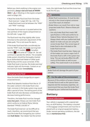 177
177 178
178 179
179 180
180 181
181 182
182 183
183 184
184 185
185 186
186 187
187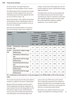 188
188 189
189 190
190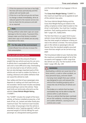 191
191 192
192 193
193 194
194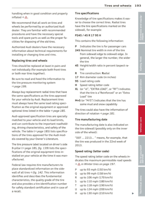 195
195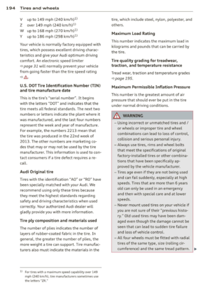 196
196 197
197 198
198 199
199 200
200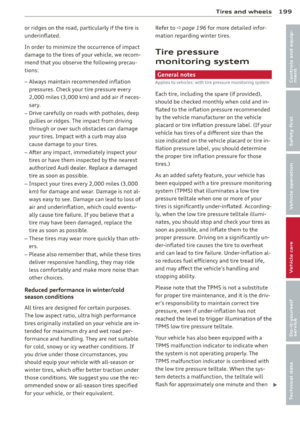 201
201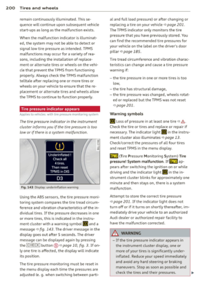 202
202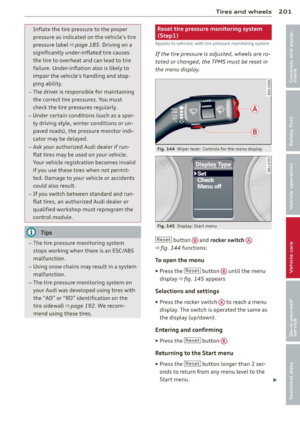 203
203 204
204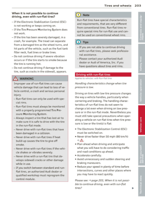 205
205 206
206 207
207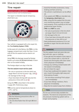 208
208 209
209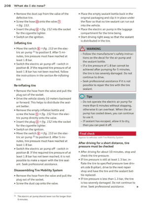 210
210 211
211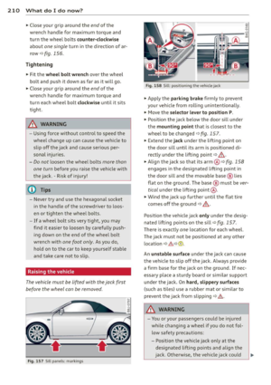 212
212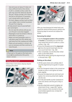 213
213 214
214 215
215 216
216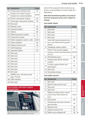 217
217 218
218 219
219 220
220 221
221 222
222 223
223 224
224 225
225 226
226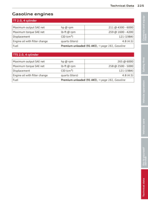 227
227 228
228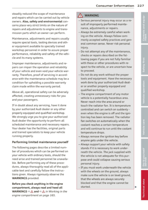 229
229 230
230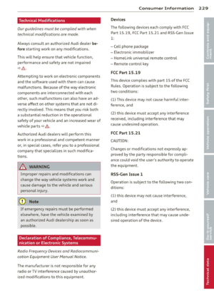 231
231 232
232 233
233 234
234 235
235 236
236 237
237 238
238 239
239 240
240 241
241 242
242 243
243